Page 1096 of 2490

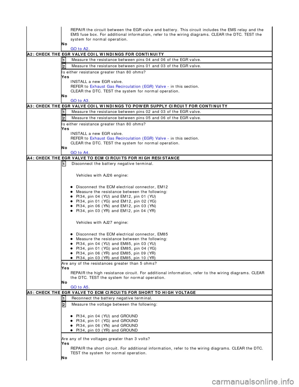
RE
PAIR the circuit between the EGR valve and battery. This circuit includes the EMS relay and the
EMS fuse box. For additional info rmation, refer to the wiring diagrams. CLEAR the DTC. TEST the
system for normal operation.
No GO to A2
.
A2: CHECK THE EGR VALVE COIL WIND
INGS FOR CONTINUITY
Meas
ure t
he resistance between pins 04 and 06 of the EGR valve.
1
Meas
ure t
he resistance between pins 01 and 03 of the EGR valve.
2
Is either resi
stance
greater
than 80 ohms?
Yes INSTALL a new EGR valve.
REFER to Exhaust Gas Recirculation (EGR) Valve
- in thi
s section.
CLEAR the DTC. TEST the syst em for normal operation.
No GO to A3
.
A3: CHECK THE EGR VALVE COIL WINDINGS TO
POWER SUPPLY CIRCUIT FOR CONTINUITY
Meas
ure t
he resistance between pins 02 and 03 of the EGR valve.
1
Meas
ure t
he resistance between pins 05 and 06 of the EGR valve.
2
Is either resi
stance greater
than 80 ohms?
Yes INSTALL a new EGR valve.
REFER to Exhaust Gas Recirculation (EGR) Valve
- in thi
s section.
CLEAR the DTC. TEST the syst em for normal operation.
No GO to A4
.
A4: CHECK THE EGR VALVE T
O ECM
CIRCUITS FOR HIGH RESISTANCE
Disc
onnect the battery negative terminal.
Vehicles with AJ26 engine:
D i
sconnect the ECM electrical connector, EM12
Meas
ure t
he resistance between the following:
PI34, pin
0
4 (YU) and EM12, pin 01 (YU)
PI34,
pi
n 01 (YG) and EM12, pin 02 (YG)
PI34, pin
0
6 (YN) and EM12, pin 03 (YN)
PI34,
pi
n 03 (YR) and EM12, pin 04 (YR)
Vehicles with AJ27 engine:
D i
sconnect the ECM electrical connector, EM85
Meas
ure t
he resistance between the following:
PI34, pin
0
4 (YU) and EM85, pin 03 (YU)
PI34, pi
n 01 (YG) and EM85, pin 04 (YG)
PI34, pi
n 06 (YR) and EM85, pin 09 (YR)
PI34, pi
n 03 (YR) and EM85, pin 10 (YR)
1
Are an
y of the resistances greater than 5 ohms?
Yes REPAIR the high resistance circui t. For additional information, refer to the wiring diagrams. CLEAR
the DTC. TEST the system for normal operation.
No GO to A5
.
A5: CHECK THE EGR VALVE T
O ECM CIRCUITS FOR SHORT TO HIGH VOLTAGE
R
e
connect the battery negative terminal.
1
Meas
ure t
he voltage between the following:
PI34, pin
0
4 (YU) and GROUND
PI34, pin
0
1 (YG) and GROUND
PI34, pin
0
6 (YN) and GROUND
PI34, pin
0
3 (YR) and GROUND
2
Are any of th
e volt
ages greater than 3 volts?
Yes REPAIR the short circuit. For addi tional information, refer to the wiring diagrams. CLEAR the DTC.
TEST the system for normal operation.
No
Page 1160 of 2490
Ite
m
Part
Number
Descr
iption
1—Fu
el tank pressure sensor (if applicable)
2—Engine m
anagement ECU
3—EVAP canister purge va
lve
4—EVAP ca
nister close valve (if applicable)
5—Engine
mana
gement fusebox - IGN supply
Circuit diagram
,
evaporative emissions systems
Page 1182 of 2490
Ite
m
Par
t
Number
De
scr
iption
1—Engine
management fuse box
2—Engine
control module (E
CM)
Circuit Diagrams (extracts only)
ECM Su
pply Voltage
Page 1183 of 2490
It
em
De
scription
1Mechanica
l guard
position sensor (potentiometer)
2Pedal demand sensors (pot
entiometers)
3Thro
ttle position sensor
4Engine
control
module (ECM)
5Throttl
e motor power relay
6EMS fuse box
7Throttl
e motor
T
hrottle Sensors and Control
Page 1187 of 2490
It
em
Par
t Number
De
scription
1—MAF
assembly
2—MAF s
ensor
3—IAT se
nsor
4—Engi
ne to vehicle harness connector
5—EMS fuse box
6—Engine
control module (ECM)
7—Charge air cool
er -
IAT sensor (superchar
ged engin
es only)
MAF
and IAT Sensors
Page 1188 of 2490
It e
m
De
scr
iption
1Engine
c
ontrol
module (ECM)
2Do
wnstream oxygen sensor (A)
3Upstream heated ox
ygen sensor
(A)
4D
o
wnstream oxygen sensor (B)
5Upstream heated ox
ygen sensor (B)
6Engine
management fuse box
Ox
yg
en Sensors
Page 1218 of 2490

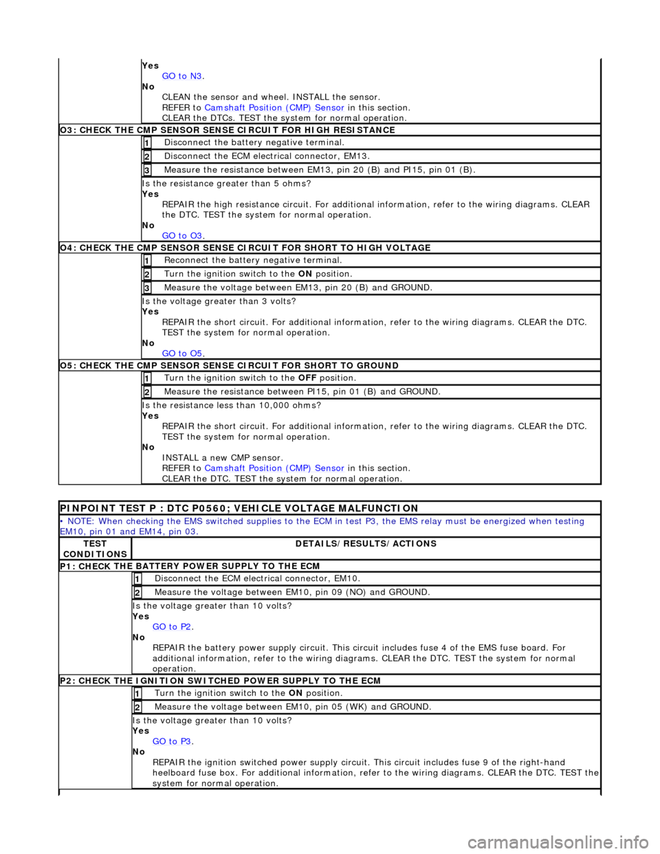
Yes
GO to N3.
No
CLEAN th
e sensor and whee
l. INSTALL the sensor.
REFER to Camshaft Position (CMP) Sensor
in this
section.
CLEAR the DTCs. TEST the system for normal operation.
O3: CHECK THE CM P SEN
SOR SENS
E CIRCUIT FOR HIGH RESISTANCE
Disc
onnect the battery negative terminal.
1
D
i
sconnect the ECM electrical connector, EM13.
2
Meas
ure t
he resistance between EM13, pin 20 (B) and PI15, pin 01 (B).
3
Is the res
istance greater than 5 ohms?
Yes REPAIR the high resistance circui t. For additional information, refer to the wiring diagrams. CLEAR
the DTC. TEST the system for normal operation.
No GO to O3
.
O4: CHECK THE CM P SEN
SOR SENSE CI
RCUIT FOR SHORT TO HIGH VOLTAGE
Re
connect the battery negative terminal.
1
Turn the ignition swi
t
ch to the ON
position.
2
Me
asure the voltage between EM13, pin 20 (B) and GROUND.
3
Is th
e volt
age greater than 3 volts?
Yes REPAIR the short circuit. For addi tional information, refer to the wiring diagrams. CLEAR the DTC.
TEST the system for normal operation.
No GO to O5
.
O5: CH ECK THE CM
P SENSOR SENSE CIRCUIT FOR SHORT TO GROUND
Turn the ignition swi
t
ch to the OFF
position.
1
Me
asure the resistance between PI15, pin 01 (B) and GROUND.
2
Is
t
he resistance less than 10,000 ohms?
Yes REPAIR the short circuit. For addi tional information, refer to the wiring diagrams. CLEAR the DTC.
TEST the system for normal operation.
No INSTALL a new CMP sensor.
REFER to Camshaft Position (CMP) Sensor
in this
section.
CLEAR the DTC. TEST the system for normal operation.
P I
NPOINT TEST P : DTC P0560; VEHICLE VOLTAGE MALFUNCTION
•
NOTE
: When checking the EMS switched supplies to the ECM
in test P3, the EMS relay must be energized when testing
EM10, pin 01 and EM14, pin 03.
TE S
T
CONDITIONS
D E
TAILS/RESULTS/ACTIONS
P1: CHECK
THE BATTERY POWER SUPPLY TO THE ECM
D
i
sconnect the ECM electrical connector, EM10.
1
Measure the
voltage between EM 10,
pin 09 (NO) and GROUND.
2
Is the vol
t
age greater than 10 volts?
Yes GO to P2
.
No
REPAIR th
e battery power supply circ
uit. This circuit includes fuse 4 of the EMS fuse board. For
additional information, refer to the wiring diagrams. CLEAR the DT C. TEST the system for normal
operation.
P2: CHECK
THE IGNITION SWITCH
ED POWER SUPPLY TO THE ECM
Turn the ignition swit
ch to the
ON position.
1
Meas
ure t
he voltage between EM10, pin 05 (WK) and GROUND.
2
Is the vol
t
age greater than 10 volts?
Yes GO to P3
.
No
REP
AIR the ignition switched power supply circuit. This circuit includes fuse 9 of the right-hand
heelboard fuse box. For a dditional information, refer to the wiri ng diagrams. CLEAR the DTC. TEST the
system for normal operation.
Page 1219 of 2490

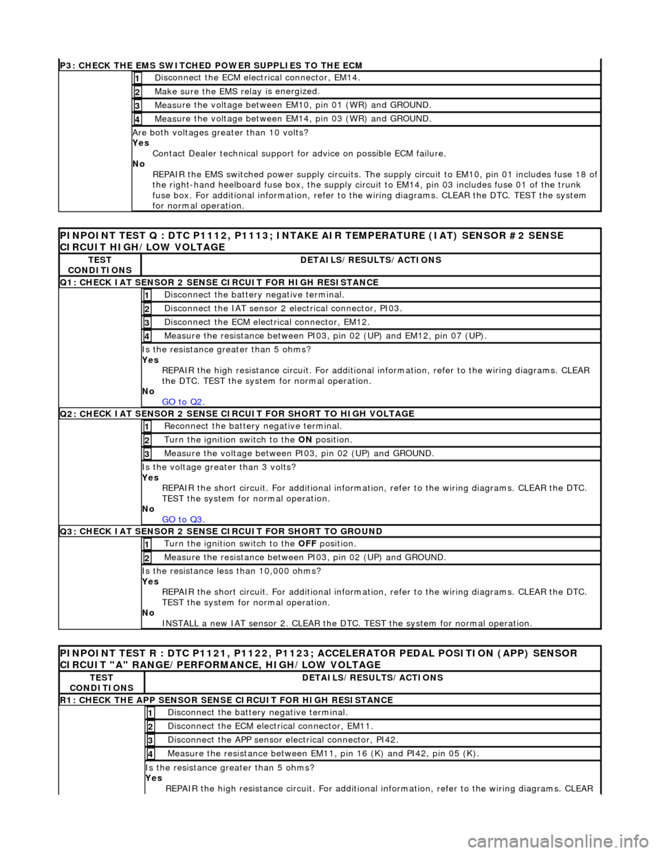
P3: CHECK
THE EMS SWITCHED
POWER SUPPLIES TO THE ECM
D
isconnect the ECM electrical connector, EM14.
1
Make sure the EMS re
lay i
s energized.
2
Meas
ure the voltage between EM10, pin 01 (WR) and GROUND.
3
Meas
ure the voltage between EM14, pin 03 (WR) and GROUND.
4
Are both
voltages greater than 10 volts?
Yes Contact Dealer technical support for advice on possible ECM failure.
No REPAIR the EMS switched power supply circuits. The su pply circuit to EM10, pin 01 includes fuse 18 of
the right-hand heelboard fuse box, the supply circuit to EM14, pin 03 includes fuse 01 of the trunk
fuse box. For additional information, refer to th e wiring diagrams. CLEAR the DTC. TEST the system
for normal operation.
PI
NPOINT TEST Q : DTC P1112, P1113; INTAKE
AIR TEMPERATURE (IAT) SENSOR #2 SENSE
CIRCUIT HIGH/LOW VOLTAGE
TE
ST
CONDITIONS
D
ETAILS/RESULTS/ACTIONS
Q1:
CHECK IAT SENSOR 2 SENSE CIRCUIT FOR HIGH RESISTANCE
Di
sconnect the battery negative terminal.
1
Di
sconnect the IAT sensor 2 electrical connector, PI03.
2
D
isconnect the ECM electrical connector, EM12.
3
Me
asure the resistance between PI03, pin 02 (UP) and EM12, pin 07 (UP).
4
Is th
e resistance greater than 5 ohms?
Yes REPAIR the high resistance circui t. For additional information, refer to the wiring diagrams. CLEAR
the DTC. TEST the system for normal operation.
No GO to Q2
.
Q2: CH
ECK IAT SENSOR 2 SENSE CIRC
UIT FOR SHORT TO HIGH VOLTAGE
R
econnect the battery negative terminal.
1
Turn the ignition swi
tch to the ON
position.
2
Measure the
voltage between PI
03, pin 02 (UP) and GROUND.
3
Is th
e voltage greater than 3 volts?
Yes REPAIR the short circuit. For addi tional information, refer to the wiring diagrams. CLEAR the DTC.
TEST the system for normal operation.
No GO to Q3
.
Q3:
CHECK IAT SENSOR 2 SENSE CIRCUIT FOR SHORT TO GROUND
Turn the ignition swi
tch to the OFF
position.
1
Meas
ure the resistance between PI03, pin 02 (UP) and GROUND.
2
Is
the resistance less than 10,000 ohms?
Yes REPAIR the short circuit. For addi tional information, refer to the wiring diagrams. CLEAR the DTC.
TEST the system for normal operation.
No INSTALL a new IAT sensor 2. CLEAR the DTC. TEST the system for normal operation.
P
INPOINT TEST R : DTC P1121, P1122, P1123;
ACCELERATOR PEDAL POSITION (APP) SENSOR
CIRCUIT "A" RANGE/PERFORMANCE, HIGH/LOW VOLTAGE
TE
ST
CONDITIONS
D
ETAILS/RESULTS/ACTIONS
R1: CHECK THE APP
SENSOR SENSE CIRCUIT FOR HIGH RESISTANCE
Di
sconnect the battery negative terminal.
1
D
isconnect the ECM electrical connector, EM11.
2
Di
sconnect the APP sensor electrical connector, PI42.
3
Meas
ure the resistance between EM11, pin 16 (K) and PI42, pin 05 (K).
4
Is th
e resistance greater than 5 ohms?
Yes REPAIR the high resistance circui t. For additional information, refer to the wiring diagrams. CLEAR