Page 1983 of 2490
Installation
6. Remove fuses and relays.
1. Note position of each relay and remove them.
2. Identify each fu se and remove them.
The value and position of each fuse is illustrated on the lid
of the trunk compartment fuse box - for all fuse boxes on
the vehicle.
1. Installation is reverse of removal.
2. Reconnect battery ground cable; refer to 86.15.15.
Page 1984 of 2490
Module Communications Network - Central Junction Box (CJB) Removal and Installation
Removal
Installation
1. Disconnect battery ground cable; refer to 86.15.19.
2. Remove heelboard trim panel.
3. Remove positive supply power cable and displace fuse box.
1. Displace cover.
Remove nut which secures posi tive cable to fuse box.
2. Disconnect cable.
3. Remove nuts.
4. Remove fuse box.
Identify and disconnect harness connectors.
5. Remove fuses and relay.
1. Remove relay.
2. Identify each fuse and remove them.
The value and position of each fuse is illustrated on the lid of the
trunk compartment fuse box - for all fuse boxes on the vehicle.
1. Installation is reverse of removal.
2. Reconnect battery ground cable; refer to 86.15.15.
Page 1985 of 2490
Module Communications Network - Front Auxiliary Junction Box
Removal and Installation
Removal
1. Disconnect battery ground cable; refer to 86.15.19.
2. Open bonnet and fit body pa intwork protection sheets.
3. Remove positive supply power cable.
1. Displace cover.
2. Remove nut.
3. Disconnect cable.
4. Remove fuse box fro m mounting panel.
1. Release securing latch, upwards, displace fuse box
outwards and remove from mounting panel.
2. Release securing tangs and remove cover.
5. Remove fuse box.
1. Identify and disconne ct harness connectors.
6. Remove fuses and relays.
Page 1986 of 2490
Installation
1. Note position of each relay and remove them.
2. Identify each fu
se and remove them.
The value and position of each fuse is illustrated on the lid
of the trunk compartment fuse box - for all fuse boxes on
the vehicle.
1. Installation is reverse of removal.
2. Reconnect battery ground cable; refer to 86.15.15.
Page 1987 of 2490
Module Communications Network - Rear Auxiliary Junction Box
Removal and Installation
Removal
1. Disconnect battery ground cable; refer to 86.15.19.
2. Open bonnet and fit body pa intwork protection sheets.
3. Remove positive supply power cable.
1. Displace cover.
2. Remove nut.
3. Disconnect cable.
4. Remove fuse box fro m mounting panel.
1. Remove nuts.
Reposition fuse box for access to connectors.
5. Remove fuse box.
Identify and disconnect harness connectors.
6. Remove fuses and relay.
Page 1988 of 2490
Installation
1. Release securing tangs and remove cover.
2. Remove relay.
3. Identify each fuse and remove them.
The value and position of each fuse is illustrated on the lid
of the trunk compartment fuse box - for all fuse boxes on
the vehicle.
1. Installation is reverse of removal.
2. Reconnect battery ground cable; refer to 86.15.15.
Page 2264 of 2490

Instrument Panel and Console - Instrument Panel Finish Panel
Removal and Installation
Removal
1. WARNINGS:
FOLLOWING DISCONNECTION OF THE BATTERY, A PERIOD
OF AT LEAST ONE MINUTE MUST BE ALLOWED TO ELAPSE
BEFORE ANY WORK IS CARRIED OUT ON AN AIR BAG MODULE.
IN THE EVENT OF A FAULT RUPTURING THE 10A BATTERY
SUPPLY FUSE (F4 LOCATED IN THE FUSE-BOX AT THE DRIVER'S
END OF THE FASCIA), THE FUSE MUST NOT BE RENEWED UNTIL
THE AIRBAG/SRS SYSTEM HAS BEEN DE-ACTIVATED. FUSES OF
ANY OTHER VALUE MUST NEVER BE USED, AS THIS CAN CAUSE
DISARM FAILURE.
Remove battery cover and disconnect ground cable from
battery terminal. Refer to 86.15.19.
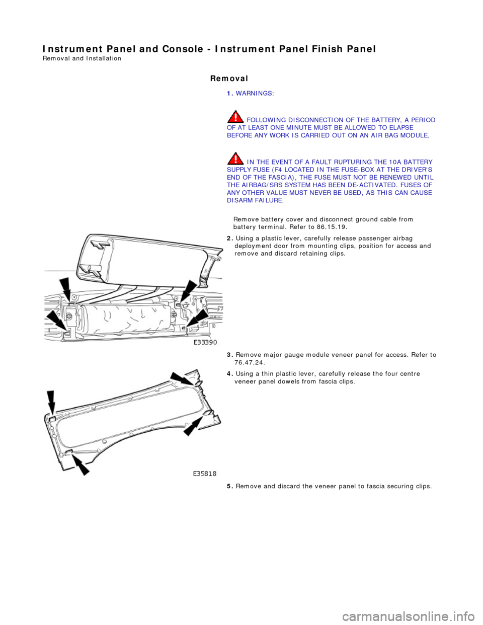
2. Using a plastic lever, carefu lly release passenger airbag
deployment door from mounting cl ips, position for access and
remove and discard retaining clips.
3. Remove major gauge module veneer panel for access. Refer to
76.47.24.
4. Using a thin plastic lever, care fully release the four centre
veneer panel dowels from fascia clips.
5. Remove and discard the veneer pa nel to fascia securing clips.
Page 2322 of 2490

Wipers and Washers - Windshield Wiper/Washer Switch
Removal and Installation
Removal
1. Ensure that steering wheel is in the straight ahead, fully
lowered and fully ex tended position.
2. Remove battery cover and disc onnect ground cable from
battery terminal. Refer to 86.15.19.
3. WARNINGS:
FOLLOWING DISCONNECTION OF THE BATTERY, A PERIOD
OF AT LEAST ONE MINUTE MUST BE ALLOWED TO ELAPSE
BEFORE ANY WORK IS CARRIED OUT ON AN AIR BAG MODULE.
FOLLOWING TEN YEARS IN SERVICE, AN AIR BAG MODULE
MUST BE REMOVED AND DISPOSED OF IN THE APPROVED
MANNER, AND A NEW AIR BAG MUST BE FITTED.
AIR BAGS CONTAIN A CHEMICAL IRRITANT. IF AN AIR BAG
IS RENEWED, THE ORIGINAL UNIT MUST BE DISPOSED OF IN
ACCORDANCE WITH CURRENT SAFETY PROCEDURES.
IN THE EVENT OF A FAULT RUPTURING THE 10A BATTERY
SUPPLY FUSE (F4 LOCATED IN THE FUSE-BOX AT THE DRIVER'S
END OF THE FASCIA), THE FUSE MUST NOT BE RENEWED UNTIL
THE AIRBAG/SRS SYSTEM HAS BEEN DE-ACTIVATED. FUSES OF
ANY OTHER VALUE MUST NEVER BE USED, AS THIS CAN CAUSE
DISARM FAILURE.
Remove driver airbag. Refer to 76.73.39.
4. Remove steeri ng wheel.
5. Remove steering column lowe r cowl. Refer to 76.46.03.
6. Remove steering column upper cowl. Refer to 76.46.02.
7. Remove driver side unders cuttle. Refer to 76.46.11.
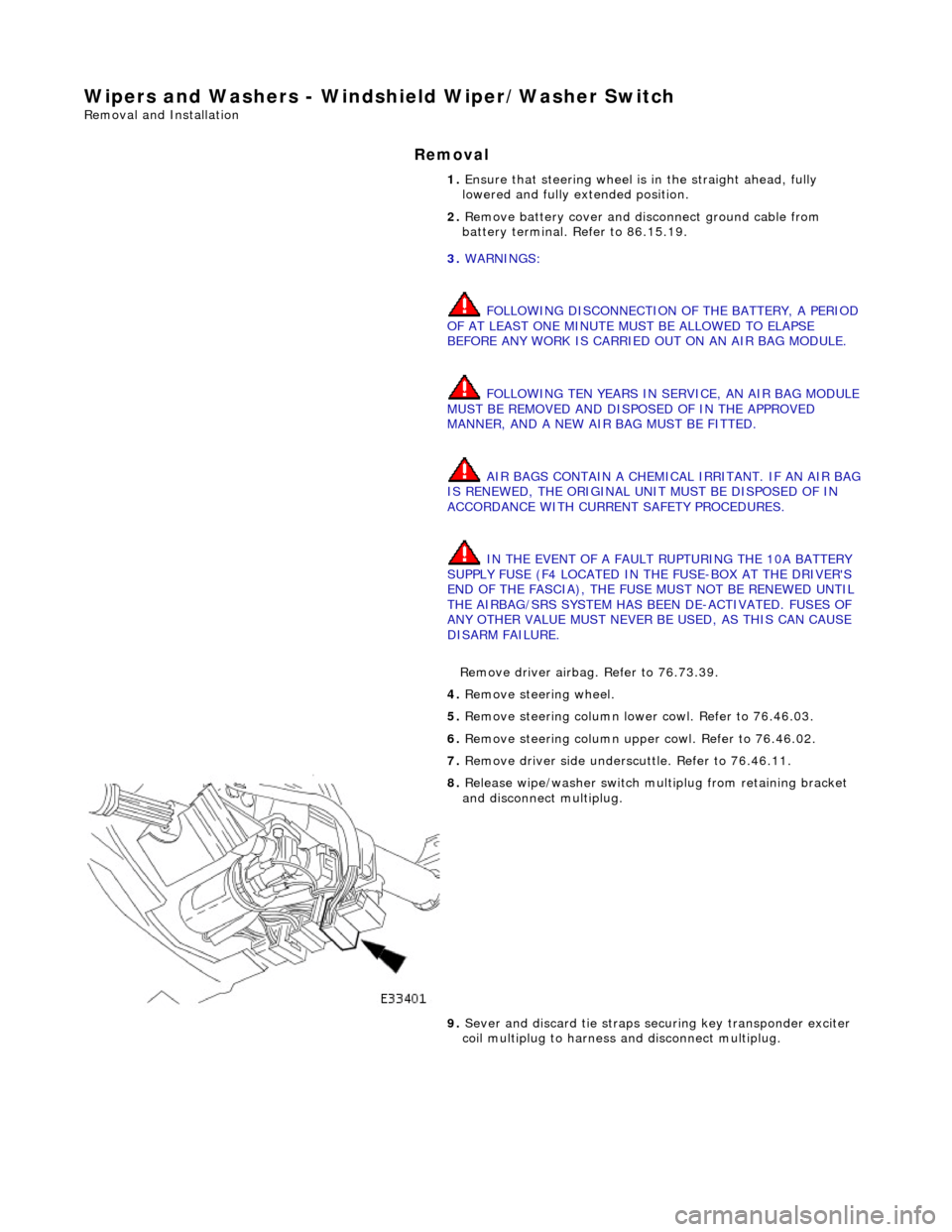
8. Release wipe/washer switch mult iplug from retaining bracket
and disconnect multiplug.
9. Sever and discard tie straps se curing key transponder exciter
coil multiplug to harness and disconnect multiplug.