1998 JAGUAR X308 Rear Wheel Speed Sensor
[x] Cancel search: Rear Wheel Speed SensorPage 436 of 2490

Pinpoint tests
W
S
S circuit: short
circuit to power
WSS f
ailure
C1
175Left -hand re
ar wheel speed
sensor (WSS) circuit failure
W S
S circuit: open
circuit
WS
S circuit: short
circuit to ground
W S
S circuit: short
circuit to power
WSS f
ailure
F
or l
eft-hand rear WSS test
s. GO to Pinpoint Test E.
C1267Modulat or valv
e failure
Supply volt
ages
to valve
solenoids or sensors out of range
Fo
r power and ground tests. GO to Pinpoint Test
A.
B1342CAN co
mmunication circuit
failure
CAN :
open circuit fault
CAN:
short circuit to
ground
CAN :
short circuit to
power
Fo
r CAN tests. GO to Pinpoint Test
F.
B1676Supply volt
age out of range
Supply voltage:
too
low
Supply volt age:
too
high
Check fo
r DTCs indicating a charging system fault.
Rectify as necesssary.
PI
NPOINT TEST A : MODULE
POWER AND GROUND SUPPLIES
TES
T
CONDITIONS
D E
TAILS/RESULTS/ACTIONS
A
1
: CHECK THE POWER SUPPLY FUSES
Make sure the igniti
on is turned off. 1
Chec
k fuses 04, 16 and 18 of the engine compartment junction box.
2
Are th
e fus
es in good condition?
Yes GO to A2
.
No
Install a new f
use as
necessary. Check the syst em for normal operation. If the fuse fails again,
check the circuit for a short circuit to ground. Refer to the electrical guides.
A2: CHECK THE PERMANENT
POWER SUPPLY (1) TO THE MODULE
Disc
onnect the ABS module connector, LF27.
1
Measure the voltage between LF
2
7, pin 09 (NR) and ground.
2
Is the vol
t
age greater than 10 volts?
Yes GO to A3
.
No Re
pair the circuit between the engine compartment
junction box, fuse 16, and LF27 pin 09. Refer to
the electrical guides. Clear the DTC, check for normal operation.
A3: CHECK THE PERMANENT
POWER SUPPLY (2) TO THE MODULE
Meas
ure t
he voltage between LF27, pin 25 (NW) and ground.
1
Is the vol
t
age greater than 10 volts?
Yes GO to A4
.
No
Re
pair the circuit between the engine compartment ju
nction box, fuse 18, and LF27 pin 25. Refer to
the electrical guides. Clear the DTC, check for normal operation.
A4: CHECK
THE IGNITION POWER SUPPLY TO THE MODULE
Make sure the ignition is on. 1
Measure the
voltage between LF 2
7, pin 20 (WU) and ground.
2
Is the vol
t
age greater than 10 volts?
Yes GO to A5
.
No Re
pair the circuit between the engine compartment ju
nction box, fuse 04, and LF27 pin 20. Refer to
the electrical guides. Clear the DTC, check for normal operation.
A5: CHECK
THE GROUND SUPPLY TO THE MODULE
Page 438 of 2490

Make sure the ignition is off. 1
Disc
onnect the ABS module connector, LF27.
2
M
e
asure the resistance between LF27, pin 17 (W) and FL01, pin 02 (W).
3
I
s
the resistance less than 5 ohms?
Yes GO to C3
.
No
Re
pair the high resistance circui
t. This circuit includes intermed iate connector, LF02. Refer to the
electrical guides. Clear the DTC, check for normal operation.
C3: CH
ECK THE WSS RETURN CIRCUIT CONTINUITY
Measure
the resistance between LF27, pin 18 (R) and FL01, pin 01 (R).
1
Is
the resistance less than 5 ohms?
Yes The WSS and circuits are OK. Check for DTCs indicating a possible module failure.
No Repair the high resistance circui t. This circuit includes intermediate connector, LF01. Refer to the
electrical guides. Clear the DTC, check for normal operation.
PI
NPOINT TEST D : CHECK THE RIGH
T-HAND REAR WSS AND CIRCUITS
•
NOTE: Check connectors and pins for damage/corrosion
(see visual inspection).
• NO
TE: Check the WSS ring condition, whee
l bearing etc. Before beginning pinpoint test s refer to the visual inspection.
TES
T
CONDITIONS
D E
TAILS/RESULTS/ACTIONS
D1: CHECK
THE WSS OUTPUT
Disc
onne
ct the ABS sensor connector, RA02.
1
Connec
t
a multimeter set
to read alternating curr ent volts (AC volts) between pins 1 and 2 of the
sensor.
2
Spin
the wheel by hand and check the meter display.
3
Doe
s
the sensor generate a voltage?
Yes GO to D2
.
No
If
the WSS ring is in good condition, install a new WSS.
REFER to: Rear Wheel Speed Sensor
(206-0
9 Anti-Lock Control, Removal and Installation).
D
2
: CHECK THE WSS SIGNAL CIRCUIT CONTINUITY
Make sure the ignition is off. 1
Disc
onnect the ABS module connector, LF27.
2
Measure t
he resistance between LF27
, pin 07 (O) and RA02, pin 01 (O).
3
Is
the resistance less than 5 ohms?
Yes GO to D3
.
No Re
pair the high resistance circui
t. This circuit includes intermed iate connector, LA02. Refer to the
electrical guides. Clear the DTC, check for normal operation.
D3:
CHECK THE WSS RETURN CIRCUIT CONTINUITY
Meas
ure t
he resistance between LF27
, pin 06 (Y) and RA02, pin 02 (Y).
1
Is
the resistance less than 5 ohms?
Yes The WSS and circuits are OK. Check for DTCs indicating a possible module failure.
No Repair the high resistance circui t. This circuit includes intermediate connector, CA09. Refer to the
electrical guides. Clear the DTC, check for normal operation.
PI
NPOINT TEST E : CHECK THE LEFT-HAND REAR WSS AND CIRCUITS
•
NOTE: Check connectors and pins for damage/corrosion
(see visual inspection).
• NO
TE: Check the WSS ring condition, whee
l bearing etc. Before beginning pinpoint test s refer to the visual inspection.
TES
T
CONDITIONS
D E
TAILS/RESULTS/ACTIONS
E1
: CHECK THE W
SS OUTPUT
Disc
onne
ct the ABS sensor connector, LA02.
1
Connec
t
a multimeter set
to read alternating curr ent volts (AC volts) between pins 1 and 2 of the
sensor.
2
Page 439 of 2490

Spin
the wheel by hand and check the meter display.
3
Doe
s the sensor generate a voltage?
Yes GO to E2
.
No
If the WSS ring is in good condition, install a new WSS.
REFER to: Rear Wheel Speed Sensor
(20
6-09 Anti-Lock Control, Removal and Installation).
E2
: CHECK THE WSS SIGNAL CIRCUIT CONTINUITY
Make sure the ignition is off. 1
Di
sconnect the ABS module connector, LF27.
2
Meas
ure the resistance between LF27
, pin 21 (U) and LA02, pin 01 (U).
3
I
s the resistance less than 5 ohms?
Yes GO to E3
.
No
Repair the high resistance circui t. This circuit includes intermediate connector, LA02. Refer to the
electrical guides. Clear the DTC, check for normal operation.
E3
: CHECK THE WSS RETURN CIRCUIT CONTINUITY
Meas
ure the resistance between LF27
, pin 22 (U) and LA02, pin 02 (U).
1
I
s the resistance less than 5 ohms?
Yes The WSS and circuits are OK. Check for DTCs indicating a possible module failure.
No Repair the high resistance circui t. This circuit includes intermediate connector, CA29. Refer to the
electrical guides. Clear the DTC, check for normal operation.
P
INPOINT TEST F : CONT
ROLLER AREA NETWORK (CAN) INTEGRITY TEST
TE
ST
CONDITIONS
D
ETAILS/RESULTS/ACTIONS
F
1: CHECK THE NETWORK INTEGRITY
FROM THE DIAGNOSTIC SOCKET
M
easure the resistance between pins 06 (Y) and 14 (G) of the diagnostic socket.
1
I
s the resistance 60 ohms?
Yes The CAN system is OK. Check for DTCs indicating a fault elsewhere.
No Check the CAN system for open an d short circuits. Refer to the electrical guides. Clear the DTC,
check for normal operation.
Page 449 of 2490

Anti-Lock Control - Rear Wheel Speed Sensor
Re
moval and Installation
Remov
al
Installation
1.
R
aise rear of vehicle and support
on stands. Refer to section
100-02.
2. Re
move wheel speed sensor.
Di
sconnect harness connector.
Re
move bolt.
3. Clean components and mating surfaces.
1. Inst
all wheel speed sensor.
Posit
ion sensor.
Install and tigh
ten bolt to 8-10 Nm.
Conne
ct harness connector.
2. Remove stands an d lower vehicle.
Page 528 of 2490

Speed an
d load
Coo
l
ant temperature
Ti
me el
apsed from start up
Cl
osed l
oop fuelling
Determination of the vapour concentration is made by stepped opening of the EVAP valve and subsequent monitoring of the
fuelling correction. This function is performed prior to purging, so that at the onse t of purging the EVAP valve can be set to
the optimum position. Should the ECM be unable to determine the concentration before purging, a default value is
employed, which is then modified whilst purging is in progress.
When the purging process is operational th e ECM modifies the basic fuelling calculation to maintain the correct air / fuel
ratio.
Purging is inhibited during fuel cut-off and stability / traction control intervention.
Coolant Temperature Sen
sor
Th
e
sensor outputs a voltage to the ECM which decreases as temperature increases.
Cooling Fans
In response to engi
ne coolant temperat
u
re and climate control system demand, the ECM will energize the cooling fans.
Climate Control Compressor
The E
C
M will allow the compressor clutch to be engaged if th
e engine temperature and load demand are normal. Should the
driver require maximum engine powe r or the coolant temperature be high, the request will be denied.
Cranking Signal
The ECM reacts to a signal fr
om th
e Body Processor Module (BPM) when the starter motor relay is energi
zed. This signal is
used to trigger starting, fu el and ignition strategies.
Engine Speed and Cranksh
aft Position
Engine
speed and cran
k position are moni
tored by a sensor which is mounted on the cylinder block (flywheel housing)
behind the crankshaft drive plat e. It indicates rotational speed to the ECM in the form of 12 pulses per crank revolution.
Engine speed is used for synchronization of fuel an d ignition systems, as well as other functions.
Camshaft Position
The ca
mshaft position sensor is mounted at
the rear of Bank 2 cylinder head on the inlet side and provides one signal every
720 degrees of crankshaft rotation. The signal, in conjunction with the signal from the crankshaft position sensor, indicates
to the ECM that the piston of cylinder 1A is approaching TDC on the compression stroke.
Variable Valve
Timing (Where Fitted)
By energi
si
ng a solenoid to allow the pass
age of pressurized oil on each of the inle t camshaft drives, the ECM can vary by a
single stepped amount, the relati ve timing of the inlet valves.
Ign
ition
Ignit
i
on spark is produced by
individual on-plug coil units.
There are two ignition amplifiers; module #1 drives coils 1A, 2B, 3B and 4A, whilst module #2 drives coils 1B, 2A, 3A and
4B. The ECM controls the amplifiers.
Page 2422 of 2490

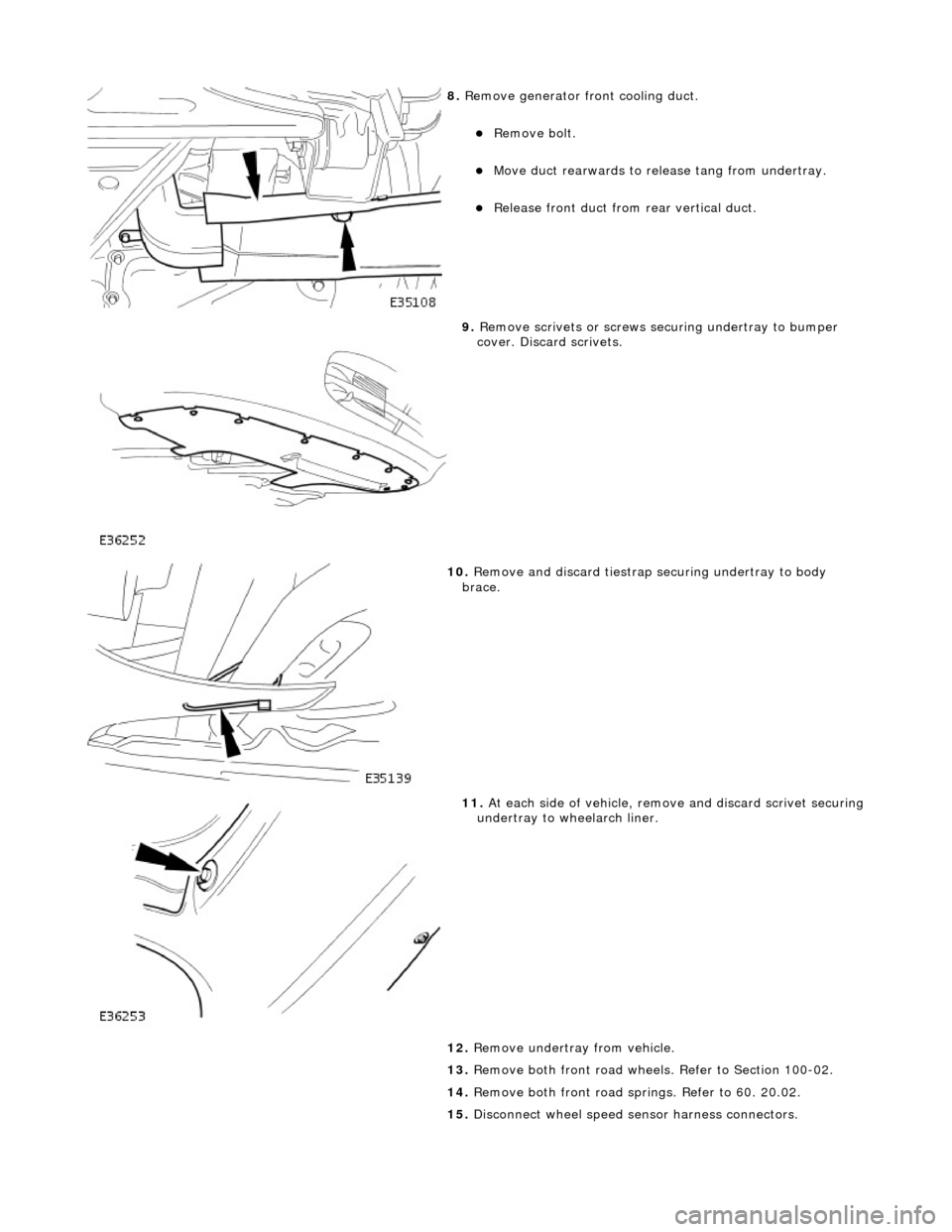
8. Remove generator front cooling duct.
Remove bolt.
Move duct rearwards to rele ase tang from undertray.
Release front duct from rear vertical duct.
9. Remove scrivets or screws se curing undertray to bumper
cover. Discard scrivets.
10. Remove and discard tiestrap securing undertray to body
brace.
11. At each side of vehicle, remo ve and discard scrivet securing undertray to wheelarch liner.
12. Remove undertray from vehicle.
13. Remove both front road wheels. Refer to Section 100-02.
14. Remove both front road springs. Refer to 60. 20.02.
15. Disconnect wheel speed sensor harness connectors.