Page 2121 of 2490

Seating - Seats Description and Operation
Front Seats
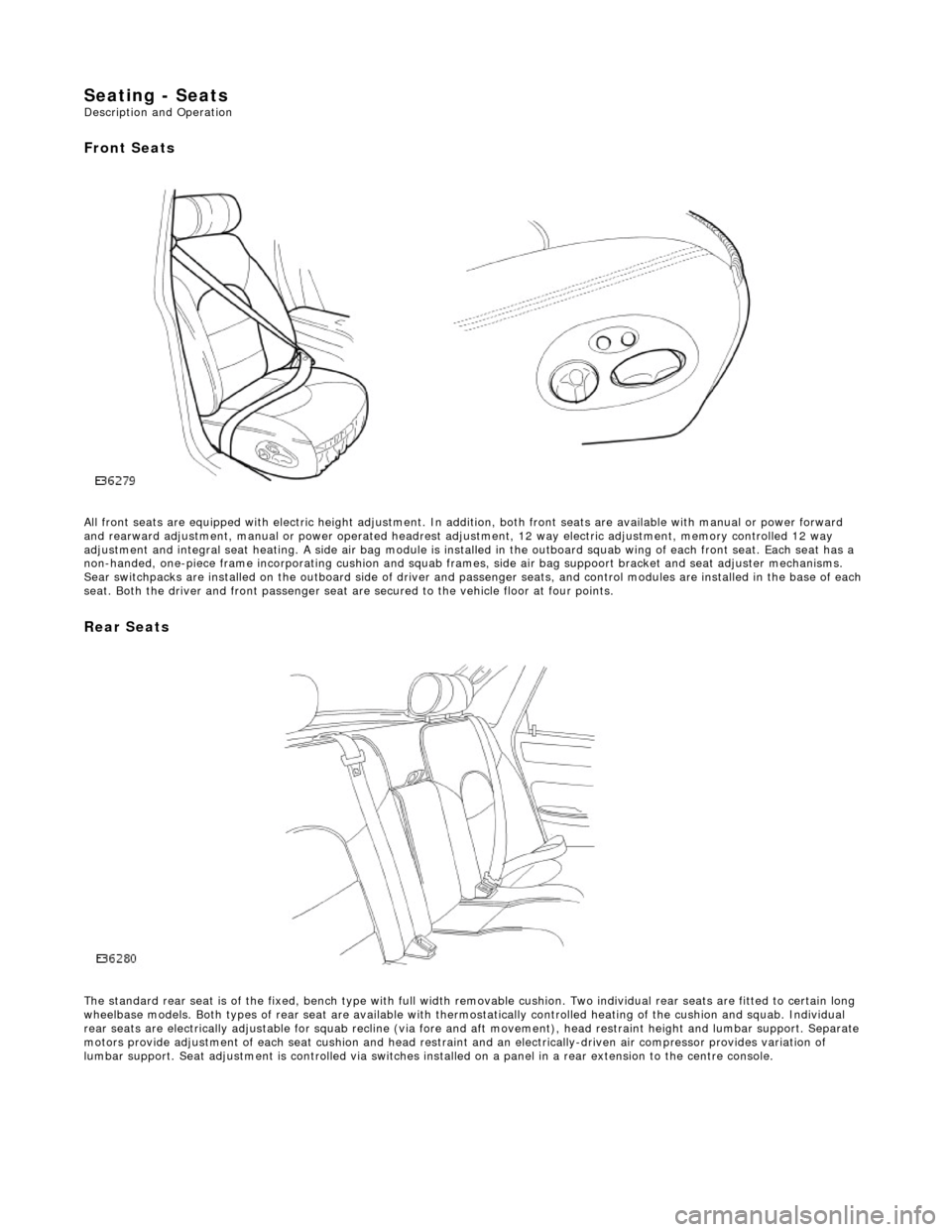
All front seats are equipped with electric height adjustment. In addition, both front seats are available with manual or power forward
and rearward adjustment, manual or powe r operated headrest adjustment, 12 way elec tric adjustment, memory controlled 12 way
adjustment and integral seat heating. A side air bag module is installed in the outboard squab wing of each front seat. Each se at has a
non-handed, one-piece frame incorporating cushion and squab frames , side air bag suppoort bracket and seat adjuster mechanisms.
Sear switchpacks are installed on the outboa rd side of driver and passenger seats, and control modules are installed in the bas e of each
seat. Both the driver and front passenger seat ar e secured to the vehicle floor at four points.
Rear Seats
The standard rear seat is of the fixed, bench type with full wi dth removable cushion. Two individual rear seats are fitted to certain long
wheelbase models. Both types of rear seat are available with thermostatically controlled heating of the cushion and squab. Indi vidual
rear seats are electrically adjustable for squab recline (via fore and aft moveme nt), head restraint height and lumbar support. Separate
motors provide adjustment of each seat cushion and head restraint and an electrica lly-driven air compressor provides variation of
lumbar support. Seat adjustment is controll ed via switches installed on a panel in a rear extension to the centre console.
Page 2122 of 2490

Seating - Front Seat
Removal and Installation
Removal
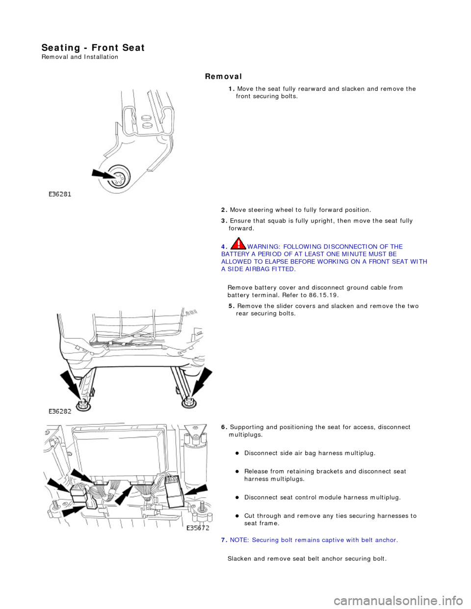
1. Move the seat fully rearward and slacken and remove the
front securing bolts.
2. Move steering wheel to fully forward position.
3. Ensure that squab is fully upright, then move the seat fully
forward.
4. WARNING: FOLLOWING DISCONNECTION OF THE
BATTERY A PERIOD OF AT LEAST ONE MINUTE MUST BE
ALLOWED TO ELAPSE BEFORE WORKING ON A FRONT SEAT WITH
A SIDE AIRBAG FITTED.
Remove battery cover and disc onnect ground cable from
battery terminal. Refer to 86.15.19.
5. Remove the slider covers an d slacken and remove the two
rear securing bolts.
6. Supporting and positioning the seat for access, disconnect
multiplugs.
Disconnect side air bag harness multiplug.
Release from retaining brackets and disconnect seat
harness multiplugs.
Disconnect seat control module harness multiplug.
Cut through and remove any ti es securing harnesses to
seat frame.
7. NOTE: Securing bolt remains captive with belt anchor.
Slacken and remove seat be lt anchor securing bolt.
Page 2149 of 2490
Seating - Front Seat Track Motor
Removal and Installation
Removal
1. WARNING: FOLLOWING DISCONNECTION OF THE
BATTERY A PERIOD OF AT LEAST ONE MINUTE MUST BE
ALLOWED TO ELAPSE BEFORE WORKING ON A FRONT SEAT WITH
A SIDE AIRBAG FITTED.
Remove battery cover and disc onnect ground cable from
battery terminal. Refer to 86.15.19.
2. Remove front seat from vehicle and place inverted on clean
work surface. Re fer to 76.70.01.
3. Release rearward (RH) tilt motor harness multiplug from
retaining bracket and di sconnect multiplug.
4. Release forward (LH) tilt motor harness multiplug from
retaining bracket and di sconnect multiplug.
5. Disconnect seat control module harness multiplugs.
6. Release heater relay (brown ) from retaining bracket.
Page 2219 of 2490

Instrument Panel and Console - Instrument Panel and Instrument Panel
Console
Description and Operation
Fascia
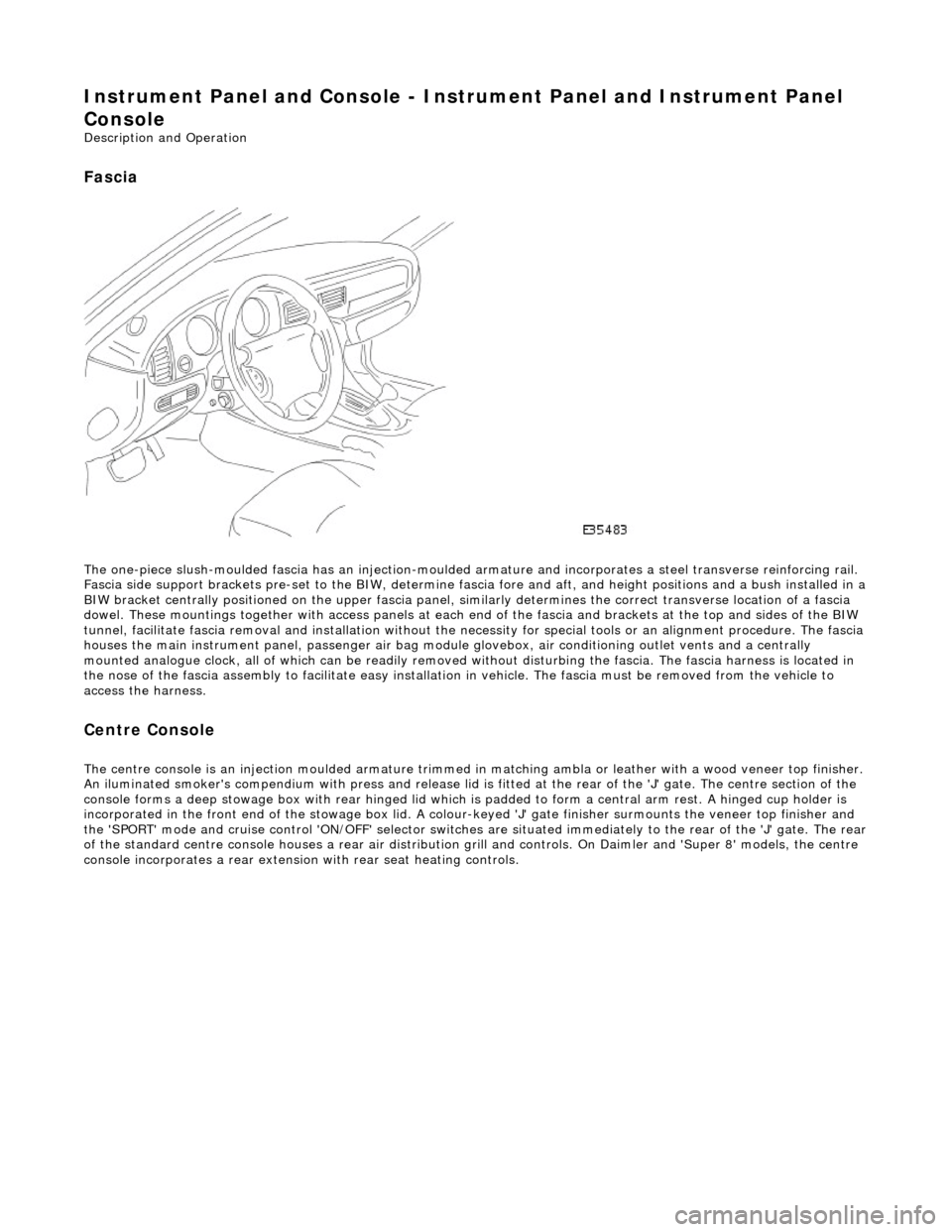
The one-piece slush-moulded fascia has an injection-moulded ar mature and incorporates a steel transverse reinforcing rail.
Fascia side support brackets pre-set to th e BIW, determine fascia fore and aft, and height position s and a bush installed in a
BIW bracket centrally positioned on the upper fascia panel, similarly determines the correct transverse location of a fascia
dowel. These mountings together with access panels at each en d of the fascia and brackets at the top and sides of the BIW
tunnel, facilitate fascia removal and instal lation without the necessity for special tools or an alignment procedure. The fasci a
houses the main instrument panel, pass enger air bag module glovebox, air conditioning outlet vents and a centrally
mounted analogue clock, all of which can be readily removed wi thout disturbing the fascia. The fascia harness is located in
the nose of the fascia assembly to facilitate easy installati on in vehicle. The fascia must be removed from the vehicle to
access the harness.
Centre Console
The centre console is an injection moulded armature trimmed in matching ambla or leather with a wood veneer top finisher.
An iluminated smoker's compendium with pr ess and release lid is fitted at the rear of the 'J' gate. The centre section of the
console forms a deep stowage box with rear hinged lid which is padded to form a central arm rest. A hinged cup holder is
incorporated in the front end of the stowage box lid. A colour-keyed 'J' gate finisher surmounts the veneer top finisher and
the 'SPORT' mode and cruise control 'ON/OFF' selector switches are situated immediately to the rear of the 'J' gate. The rear
of the standard centre console houses a re ar air distribution grill and controls. On Daimler and 'Super 8' models, the centre
console incorporates a rear extensio n with rear seat heating controls.
Page 2221 of 2490
Instrument Panel and Console - Climate Control Assembly Housing
Removal and Installation
Removal
Installation
1. Move 'J' gate selector to position 'D.'
2. Remove battery cover and disc onnect ground cable from
battery terminal. Refer to 86.15.19.
3. Remove 'J' gate finish er. Refer to 76.25.24.
4. Remove 'J' gate finisher reta ining plate.Refer to 76.25.26.
5. Remove centre console veneer panel. Refer to 76.47.26.
6. Remove radio and console. Refer to operations in this section.
7. Disconnect air conditioning panel flying lead multiplug (blue)
in LH side of transmission tunnel.
8. Slacken and remove remaining screw securing air
conditioning panel console to BIW.
9. Withdraw air conditioning panel and console for access and
disconnect the harness multiplug behind panel.
10. Remove air conditioning panel from vehicle.
11. Remove panel from console.
1. Fit air conditioning panel to console.
Page 2224 of 2490
Instrument Panel and Console - Floor Console
Removal and Installation
Removal
1. Turn ignition switch to posi tion II and apply footbrake.
2. Move gear selector to the the 'D' position. and release
footbrake.
3. Turn ignition switch to position'O'
4. Remove battery cover and disc onnect ground cable from
battery terminal. Refer to 86.15.19.
5. Where fitted, remove centre cons ole rear extension. Refer to
76.25.05.
6. Remove fascia centre veneer panel. Refer to 76.47.06.
7. Using a thin plastic lever, ca refully release the rear air
distribution control grill tang s at top and sides and remove
grill complete with veneer panel and control.
8. Disconnect cigar lighter and ashtray illumination harness
(white) multiplug at RH rear. of console.
9. Slacken and remove the two co nsole rear securing screws.
10. Remove 'J' gate finisher and veneer panel. Refer to 76.25.24
and 76.25.26.
11. Remove fascia centre veneer panel. Refer to 76.47.06.
Page 2226 of 2490
multiplug.
11.
Where applicable, install console rear extension. Refer to
76.25.05.
12. Fit and firmly seat air distribu tion control grill to rear of
console.
13. Move 'J' gate selector to 'P'.
14. Connect ground cable to batt ery terminal and fit battery
cover. refer to 86.15.15.
Page 2227 of 2490

Instrument Panel and Console - Floor Console Ashtray
Removal and Installation
Removal
Installation
1.
Remove battery cover and disc onnect ground cable from
battery terminal. Refer to 86.15.19.
2. Remove center console for access . Refer to operations in this
section.
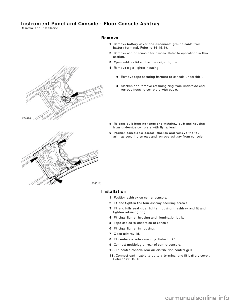
3. Open ashtray lid and remove cigar lighter.
4. Remove cigar lighter housing.
Remove tape securing harnes s to console underside..
Slacken and remove retaining ring from underside and
remove housing complete with cable.
5. Release bulb housing tangs and withdraw bulb and housing
from underside complete with flying lead.
6. Position console for access, slacken and remove the four
ashtray securing screws and remove ashtray from console.
1. Position ashtray on center console.
2. Fit and tighten the four ashtray securing screws.
3. Fit and fully seat cigar lighter housing in ashtray and fit and
tighten retaining ring.
4. Fit cigar lighter housing and illumination bulb.
5. Tape cables to underside of console.
6. Fit cigar lighter in housing.
7. Close ashtray lid.
8. Fit center console assembly. Refer to 76..
9. Connect multiplug at rear of centre console.
10. Fit centre console rear air distribution control grill.
11. Connect earth cable to battery te rminal and fit battery cover.
Refer to 86.15.15.