1998 JAGUAR X308 303-03
[x] Cancel search: 303-03Page 522 of 2490

diverter val
ve (if fitted) and oil filter.
Main
bearings
which are grooved in the upper positions and plain in
the lower positions. They are manufactured from
aluminium / tin material.
A c
rankshaft with under
cuts and rolled fillets for extra strength.
Fracture
-split connecting rods in sintered-forged steel.
Brackets
bolted to the front of
the cylinder
block are used to mo unt all accessories.
A sin
gle, seven ribbed vee belt
drives the accessories.
An au
tomatic belt tensioner for the front accessory drive,
incorporating a wear indicator.
An advanced en
gine management system inco
rporating electronic throttle control.
The un
it meets the requirements of the CARB OBDII USA legislation.
Ancillary Systems
The an
ci
llary systems, driven by the engine, each have a
detailed Description and Operation along with Diagnostic
Procedures, and Removal and Installation instructions ; refer to the following sections of this manual:
Power Steeri
ng Pump - Section 211-02
Ai
r Conditioning Compressor - Sectio
n 412-03
Engine
C
ooling Pump - Section 303-03
Generator
- Sectio
n 414-02
The drive belt, idler pulley and automatic tensioner are described in Section 303-05.
The engine starting system is described in Section 303-06.
En
gine Management and Emission Control System
Engine Control Modu
le (ECM)
Engine
management and exhaust emissions are controlled by the ECM, which has the
following main functions:
Fu
el injection
Idle
s
peed
Ignition Ev
aporative loss system
Engine
cooling fans Clim
ate control compressor clutch demand
The microprocessor within the ECM receiv es signals from various sensors and other modules and uses a pre-determined
program to compute engine management functions.
Adaptive functions are incorporated in the ECM to cater for co ntinuous adjustments to its computations to suit prevailing
conditions. Because the system also controls emissions to suit all modes, neither CO levels nor idle speed require service
attention or adjustment, except if an error should occur.
On Board Diagnostics are controlled by the ECM with the continuous monitoring of incoming signals and the subsequent
verification against what the module expects to 'see'. Should a si gnal be incorrect or missing, the ECM will substitute a fixed
value to provide the 'limp home mode' and alert the driver of the problem. Fixed values may be adopted for:
Transmission oil
temperature
Mechanica
l
guar
d position
Throttle blade angle Camshaft position
Inta
k
e air temperature
Diagnostic trouble codes (DTC), including OBD II codes, are stored in the ECM memo ry and can be read by an appropriate
retrieval tool.
Should either the ECM or TCM fa il, ensure that the control housing cooling fan is operating correctly. Failure of the cooling
fan MUST be rectified before renewing a control module and details of a fa n failure should accompany a returned control
module.
Page 564 of 2490

3.
If
the damper is not to be installed immediately, the transit
ring should be installed temporarily to the seal.
4. Install a new O-ri
ng seal to the damper.
5. Instal
l the crankshaft damper.
Apply petroleum jelly to the damper
bore and O-ring seal.
1. Install the damper onto the crankshaft.
2. Install the split locking ring onto the crankshaft,
inside the centre bo re of the damper.
3. Install, but do not tigh ten, a new damper securing
bolt.
6. CAUTIO
N: Under no circumstan
ces should the crankshaft
setting peg 303-531 be used in the following operations, to lock
the crankshaft.
Tighten the damper securing bolt.
1. Reposition the damper to allow access to the bolt holes for installing the locking tool.
2. Install the locking tool (303-191 and 303-191-03) to the damper using the bolts provided.
3. Fully tighten the damper securing bolt to 364-386 Nm.
7. Re
move the locking tool from the damper.
8. Install the drive belt to the fr ont accessory drive. Refer to
Operation 12.10.40.
9. Install the supercharger driv e belt. Refer to Operation
18.50.08.
10. Install the twin fan and motor assembly. Refer to Section
303-03.
11. Install the plastic mesh cove r to the torque converter
housing; if removed for acce ss to lock the crankshaft.
12. Reset the engine compartment cover to the normal position
and connect the gas struts.
13. Remove the paintwork protection sheets and close the engine
compartment.
Page 604 of 2490

6.
CA
UTION:
Under no circumstances should the crankshaft setting peg 303-531 be used in the following
operations, to lock the crankshaft.
Tighten the damper securing bolt. 1. Reposition the damper to allow access to the bolt holes for installing the locking tool.
2. Install the locking tool (303-191 and 303-191-03) to the damper using the bolts provided.
3. Fully tighten the damper securing bolt to 364-386 Nm.
7. Remove the locking tool from the damper.
8. Install the drive belt to the front accessory drive. Refer to Operation <<12.10.40>>.
9. Install the supercharger drive belt. Refer to Operation <<18.50.08>>.
10. Install the twin fan and motor assembly. Refer to Section 303-03.
11. Install the plastic mesh cover to the torque converter housing; if removed for access to lock the
crankshaft.
12. Reset the engine compartment cover to the normal position and connect the gas struts.
13. Remove the paintwork protection sheets and close the engine compartment.
Page 1230 of 2490

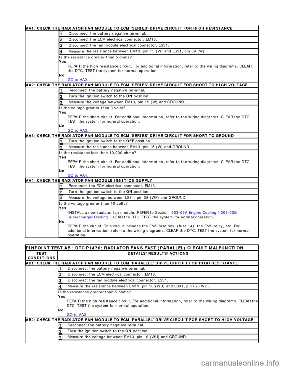
AA1: CHECK THE RA
DIATOR FAN MODULE TO ECM
'SERIES' DRIVE CIRCUIT FOR HIGH RESISTANCE
Disc
onnect the battery negative terminal.
1
D
i
sconnect the ECM electrical connector, EM13.
2
Disc
onne
ct the fan module electrical connector, LS31.
3
Meas
ure t
he resistance between EM13, pin 15 (W) and LS31, pin 09 (W).
4
Is th
e res
istance greater than 5 ohms?
Yes REPAIR the high resistance circui t. For additional information, refer to the wiring diagrams. CLEAR
the DTC. TEST the system for normal operation.
No GO to AA2
.
AA2: CHECK THE RA
DIATOR FAN MODULE TO ECM 'SER
IES' DRIVE CIRCUIT FOR SHORT TO HIGH VOLTAGE
Re
connect the battery negative terminal.
1
Turn the ignition swit
ch to the
ON position.
2
Measure t
he voltage between EM13, pin 15 (W) and GROUND.
3
Is the volt
age greater than 3 volts?
Yes REPAIR the short circuit. For addi tional information, refer to the wiring diagrams. CLEAR the DTC.
TEST the system for normal operation.
No GO to AA3
.
AA3: CHECK THE R A
DIATOR FAN MODULE TO ECM
'SERIES' DRIVE CIRCUIT FOR SHORT TO GROUND
Turn the ignition swit
ch to the
OFF position.
1
Meas ure t
he resistance between EM13, pin 15 (W) and GROUND.
2
Is
t
he resistance less than 10,000 ohms?
Yes
REPAIR the short circuit. For addi tional information, refer to the wiring diagrams. CLEAR the DTC.
TEST the system for normal operation.
No GO to AA4
.
AA4:
CHECK THE RADIATOR FAN MODULE IGNITION SUPPLY
Reconn
ect the ECM electrical connector, EM13.
1
Turn the ignition swit
ch to the
ON position.
2
Measure the voltage between LS 31,
pin 08 (WP) and GROUND.
3
Is the vol
t
age greater than 10 volts?
Yes INSTALL a new radiator fan module. REFER to Section 303
-03
A Engine Cooling
/
303-03B Supercharger Cooli
ng
. CLEA
R the DTC. TEST the sy stem f
or normal operation.
No REPAIR the circuit. This circui t includes the EMS fuse box, (f use 14), the EMS relay, etc. For
additional information, refer to the wiring diagrams. CLEAR the DT C. TEST the system for normal
operation.
PINPOINT TE ST
AB : DTC P1476; RADIATOR
FANS FAST (PARALLEL) CIRCUIT MALFUNCTION
TES
T
CONDITIONS
D E
TAILS/RESULTS/ACTIONS
AB1
:
CHECK THE RADIATOR FAN MODULE TO ECM
'PARALLEL' DRIVE CIRCUIT FOR HIGH RESISTANCE
Disc
onnect the battery negative terminal.
1
D
i
sconnect the ECM electrical connector, EM13.
2
Disc
onne
ct the fan module electrical connector, LS31.
3
Meas
ure t
he resistance between EM13, pin 16 (WU) and LS31, pin 07 (WU).
4
Is th
e res
istance greater than 5 ohms?
Yes REPAIR the high resistance circuit. For additional information, refer to the wiring diagrams. CLEAR the
DTC. TEST the system for normal operation.
No GO to AA2
.
AB2:
CHECK THE RADIATOR FAN MODULE TO ECM 'PARALLEL' DRIVE CIRCUIT FOR SHORT TO HIGH VOLTAGE
R
e
connect the battery negative terminal.
1
Turn the ignition swi
t
ch to the ON
position.
2
Measure t
he voltage between EM13, pin 16 (WU) and GROUND.
3
Page 1760 of 2490

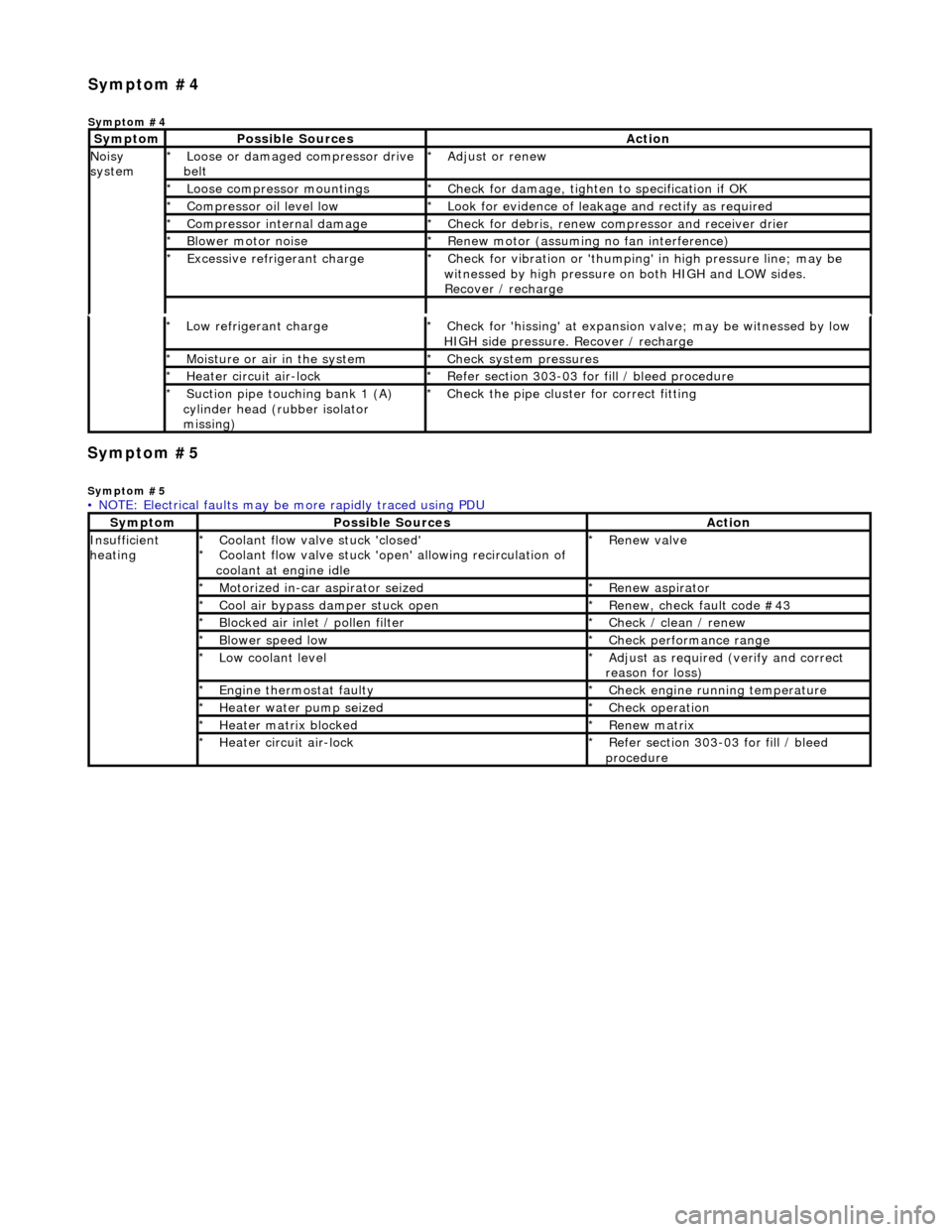
Symp
tom #5
Sy
m
ptom #5
Low r
e
frigerant charge
*
Check f or 'hissi
ng' at expansion
valve; may be witnessed by low
HIGH side pressure. Recover / recharge
*
Moi
s
ture or air in the system
*
Chec k syst
em pressures
*
Heat er ci
rcuit air-lock
*
R e
fer section 303-03 for fill / bleed procedure
*
Suct ion
pipe touching bank 1 (A)
cylinder head (rubber isolator
missing)
*
Check the pi
pe cluster for correct fitti
ng
*
• NOTE: Electrical faults may be more rapidly traced using PDU
Sym
ptom
Possib
l
e Sources
Acti
o
n
Insuffi
ci
ent
heating
Coo l
ant flow valve stuck 'closed'
Coolant flow valve stuck 'open' allowing recirculation of
coolant at engine idle
*
*
Re
new v
alve
*
Motorized in-car aspirator sei zed
*R e
new aspirator
*
Coo l
air bypass damper stuck open
*
Re new,
check fault code #43
*
B l
ocked air inlet / pollen filter
*
Chec k / cl
ean / renew
*
B l
ower speed low
*
Check performance range
*
Low cool ant
level
*
Adjust as req u
ired (verify and correct
reason for loss)
*
Engine
t
hermostat faulty
*
Check engine r u
nning temperature
*
Heater water pump seized
*Chec k op
eration
*
Heater ma trix
blocked
*
Re new m
atrix
*
Heater circui t
air-lock
*
R e
fer section 303-03 for fill / bleed
procedure
*
Sym
p
tom #4
Sym
ptom #4
Sy
m
ptom
Possib
l
e Sources
Acti
o
n
No
i
sy
system
Loose or damaged compressor drive
belt
*Adjust or r
e
new
*
Loose compressor mountings
*Check f o
r damage, tighten to specification if OK
*
Compressor oil level l
ow
*
Look for evidence of l
eakag
e and rectify as required
*
Compressor internal dama ge
*Check f o
r debris, renew compressor and receiver drier
*
B l
ower motor noise
*
Re new m
otor (assuming no fan interference)
*
Excessive refrige rant charge
*Check f o
r vibration or 'thumping'
in high pressure line; may be
witnessed by high pressure on both HIGH and LOW sides.
Recover / recharge
*
Page 1838 of 2490

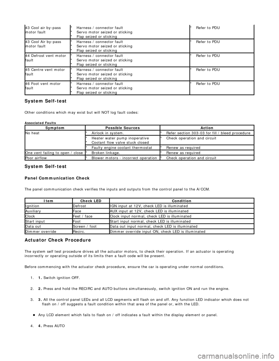
System Self-test
Other conditions which may exist but will NOT log fault codes:
Associated Faults
System Self-test
Panel Communication Check
The panel communication check veri fies the inputs and outputs from the control panel to the A/CCM.
Actuator Check Procedure
The system self test procedure drives all the actuator moto rs, to check their operation. If an actuator is operating
incorrectly or operating outside of its limi ts then a fault code will be present.
Before commencing with the actuator check procedure, ensure the ca r is operating under normal conditions.
1. 1. Switch ignition OFF.
2. 2. Press and hold the RECIRC and AUTO buttons simult aneously, switch ignition ON and run the engine.
3. 3. All the control panel LEDs and all LCD segments will flas h on and off. Any function LED indicator which does not
flash on / off suggests a fault condition within that area of the panel or, with the LED.
Any LCD element which fails to flash on / off indicates a fault within the display element or panel.
4. 4. Press AUTO
43 Cool air by-pass
motor faultHarness / connector fault
Servo motor seized or sticking
Flap seized or sticking
*
*
*Refer to PDU
*
43 Cool Air by-pass
motor faultHarness / connector fault
Servo motor seized or sticking
Flap seized or sticking
*
*
*Refer to PDU
*
44 Defrost vent motor
faultHarness / connector fault
Servo motor seized or sticking
Flap seized or sticking
*
*
*Refer to PDU
*
45 Centre vent motor
faultHarness / connector fault
Servo motor seized or sticking
Flap seized or sticking
*
*
*Refer to PDU
*
46 Foot vent motor
faultHarness / connector fault
Servo motor seized or sticking
Flap seized or sticking
*
*
*Refer to PDU
*
SymptomPossible SourcesAction
No heatAirlock in system.
*Refer section 303-03 for fill / bleed procedure
*
Heater water pump inoperative
Coolant flow valve stuck closed
*
*Check operation and circuit
*
Faulty engine coolant thermostat
*Renew as required
*
One vent failing to open / closeBroken linkage.
*Renew as required
*
Poor airflowBlower motors - incorrect operation
*Check operation and circuit
*
ItemCheck LEDCondition
IgnitionDefrostIGN input at 12V, check LED is illuminated
AuxiliaryFaceAUX input at 12V, check LED is illuminated
ClockFeet / faceClock input normal, check LED is illuminated
Start inputFootStart input normal, check LED is illuminated
Data outScreen / footData out input normal, check LED is illuminated
Dimmer overrideRecirc.Dimmer override input ON, check LED is illuminated