Page 1076 of 2490
It e
m
Par
t
Number
De
scr
iption
1—Engine
control module (E
CM)
2—Ignition control
modules (1 and 2)
3—Igniti
on coils - 1A (bank 1, coil 1 only drawn)
4—Spark
plug - 1
A (bank 1, plug 1 only drawn)
5—Igni
ti
on coils supply relay
6—Engine
management system fuse-box
Ci
rcui
t Diagram,
Ignition System
Page 1092 of 2490
Engine Ignition - Spark
Plugs
Re
mo
val and Installation
Remov
a
l
Installation
1.
Disc onne
ct battery ground cable (IMPORTANT, see SRO
86.15.19 for further information).
2. Remove air intake tube / meter / air cleaner cover for access;
refer to 19.10.30.
3. Remove ignition coils; refer to 18.20.41 (bank 1) and 18.20.42
(bank 2).
4. Re
move spark plugs.
5. Clean all components as necessary.
1. Installation
is a reversal
of the removal procedure.
Check ele
ctrode gap is to the
correct specification. Refer
to the Specification Section and current Service Bulletins.
Apply su
itable lubricant e.
g. Neverseez Compound, to
lower four threads of spark plug(s) adjacent to the
electrodes.
The lubrican t must be applied
to full thread depth for at
least 180° of the thread circumference.
T h
e electrodes must not be
contaminated during this
process.
2.
Page 1107 of 2490
Intake Air Distribution and Filtering - Intake Air Distribution and Filtering
Description an
d Operation
I
ntake Air Distribution and Filtering - Normally Aspirated Vehicles
Air Intake Asse
mbly
The air cleaner assembly consists of a two piece box containing the air filter, an airflow/temperature unit and the air intake
duct which connects to the top of the throttle assembly. The en gine full load breather feeds into the intake duct from the
bank 1 camshaft cover. A tuned stub on the ai r intake duct reduces the intake noise level.
Mass Air Flow and Temperature Sensors
The intake air is monitored by the Mass Air Flow (MAF) sensor assembly which is fitted at the outlet of the air filter
assembly. Two sensors are incorporated in the MAF sensor assembly, measuring air flow and temperature (temperature
sensor arrowed); both sensors provide anal ogue signal inputs to the engine control module (ECM) and are further described
in Section 303-14.
Page 1111 of 2490

the
intake elbow provide connections for vacuum actuators and are also used to redirect emissions into the engine.
On the right-hand side of the elbow a la rge diameter pipe connects to the brake servo. The smaller pipe provides a vacuum
feed to the fuel rail pressure regulator and throttle cruise control system. On the le ft-hand side of the elbow the front pipe
supplies vacuum control for the evaporative emissions system valves.
Emissions from the engine part load breather (bank 2) and pu rged fuel vapor from the EVAP valve are drawn via a common
T piece into the left-hand side of the intake elbow. Re-cir culated exhaust gas enters the intake elbow via the EGR valve
which is mounted directly on the rear of the elbow : where the EGR system is not used, a blanking plate is fitted.
The fuel system, throttle and emission control system s are described more fully in the relevant sections.
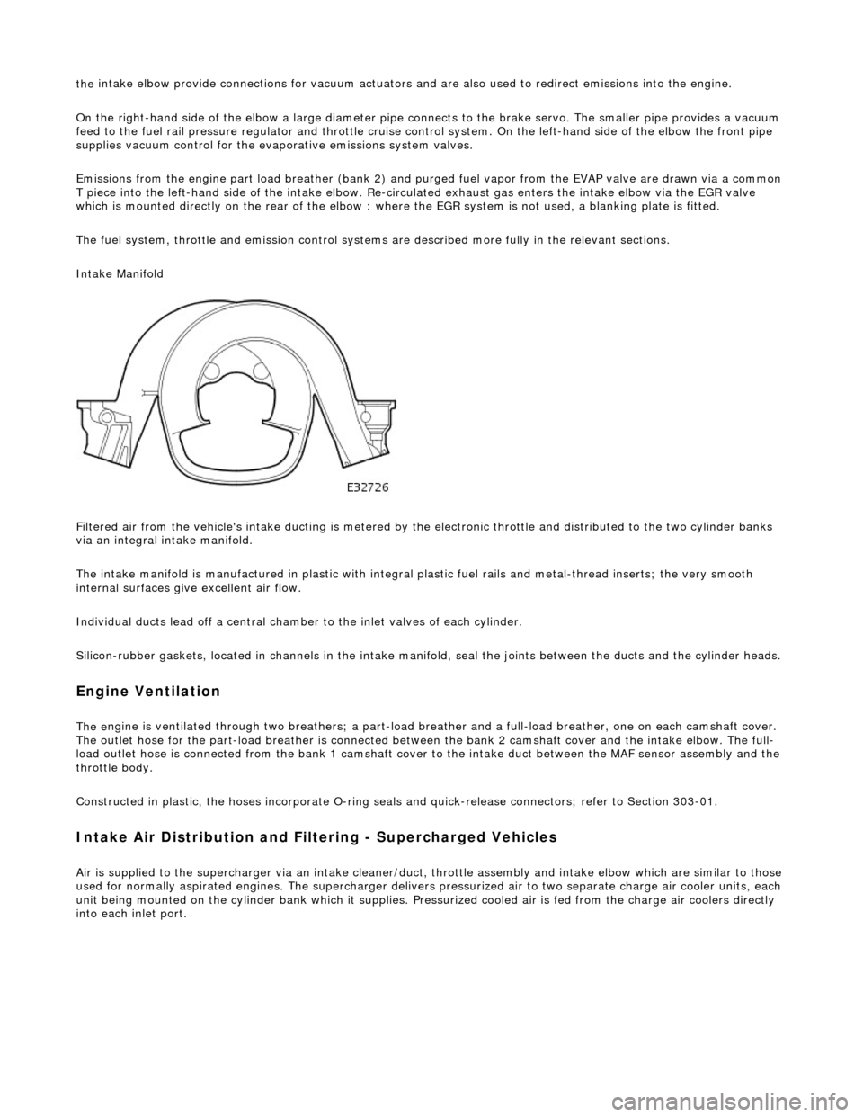
Intake Manifold
Filtered air from the vehicle's intake ducting is metered by th e electronic throttle and distributed to the two cylinder banks
via an integral intake manifold.
The intake manifold is manufactured in plastic with integral plastic fuel rails and metal-thread inserts; the very smooth
internal surfaces give excellent air flow.
Individual ducts lead off a central chamber to the inlet valves of each cylinder.
Silicon-rubber gaskets, loca ted in channels in the intake manifold, seal th e joints between the ducts and the cylinder heads.
Engine Ventilation
The e
ngine is ventilated through two brea
thers; a part-load breather and a full-load breather, one on each camshaft cover.
The outlet hose for the part-load breather is connected between the bank 2 camshaft cover and the intake elbow. The full-
load outlet hose is connected from the bank 1 camshaft cover to the intake duct between the MAF sensor assembly and the
throttle body.
Constructed in plastic, the hoses incorporate O-ring seal s and quick-release connectors; refer to Section 303-01.
I
ntake Air Distribution and Filtering - Supercharged Vehicles
Ai
r is supplied to the supercharger via an
intake cleaner/duct, throttle assembly and intake elbow which are similar to those
used for normally aspirated engines. The su percharger delivers pressurized air to two separate charge air cooler units, each
unit being mounted on the cy linder bank which it supplies. Pr essurized cooled air is fed from the charge air coolers directly
into each inlet port.
Page 1112 of 2490
The air cleaner assembl y
consists of a tw
o piece box containing the ai r filter, an airflow/temperature unit (MAF sensor) and
the air intake duct which connects to the top of the throttle assembly. The engine full load breather feeds into the intake
duct from the bank 1 camshaft cover. Two tuned stubs on the air intake duct reduce the intake noise level.
Temperature Sensor
A second intake air temperature sensor (IAT sensor 2) is fitted at the outlet of the bank 1 charge air cooler. The sensor
provides an input to the ECM.
Air Intake Asse mbly
Page 1113 of 2490

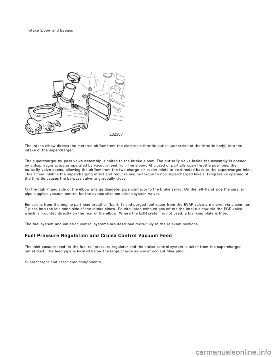
The intake elbow di
rects the metered airflow from the electronic throttle outlet (und
erside of the throttle body) into the
intake of the supercharger.
The supercharger by-pass valve assembly is bolted to the intake elbow. The butterfly valve inside the assembly is opened
by a diaphragm actuator operated by vacu um feed from the elbow. At closed or partially open throttle positions, the
butterfly valve opens, allowing th e airflow from the two charge air cooler inlets to be directed back to the supercharger inlet .
This action inhibits the supercharging e ffect and reduces engine torque to non supercharged levels. Progressive opening of
the throttle causes the by-pass valve to gradually close.
On the right-hand side of the elbow a la rge diameter pipe connects to the brake servo. On the left-hand side the smaller
pipe supplies vacuum control for the evaporative emissions system valves.
Emissions from the engine part load breather (bank 1) and pu rged fuel vapor from the EVAP valve are drawn via a common
T piece into the left-hand side of the intake elbow. Re-cir culated exhaust gas enters the intake elbow via the EGR valve
which is mounted directly on the rear of the elbow. Where the EGR system is not used, a blanking plate is fitted.
The fuel system and emission control systems are described more fully in the relevant sections.
Fuel Pressure Regula
tion and
Cruise Control Vacuum Feed
The inlet v
acuum feed fo
r the fuel rail pressure regula tor and the cruise control system is taken from the supercharger
outlet duct. The feed pipe is located below the large charge air cooler coolant filler plug.
Superchar
ger
and associated components
Inta
ke Elbow and Bypass
Page 1114 of 2490
P a
rts List
It
e
m
Par
t
Number
De
scr
iption
1—Inta
k
e Air Temperature Sensor 2
2—Charge Air Cooler - Bank 1
3—Charge Air Cooler - Bank 2
4—Charge Air Cooler - Inlet Duct
5—Supercharger
Outlet D
uct
6—Supercharger
7—Supercharger
Pull
ey
8—Supercharger
Dri
ve Belt
Page 1115 of 2490

is at
tached to the three mounting bosses between the V of the cylinder block
has a fil
led for life inte
rnal lubrication system
is po
sitively aligned with the drive
belt by a doweled mounting bracket
C
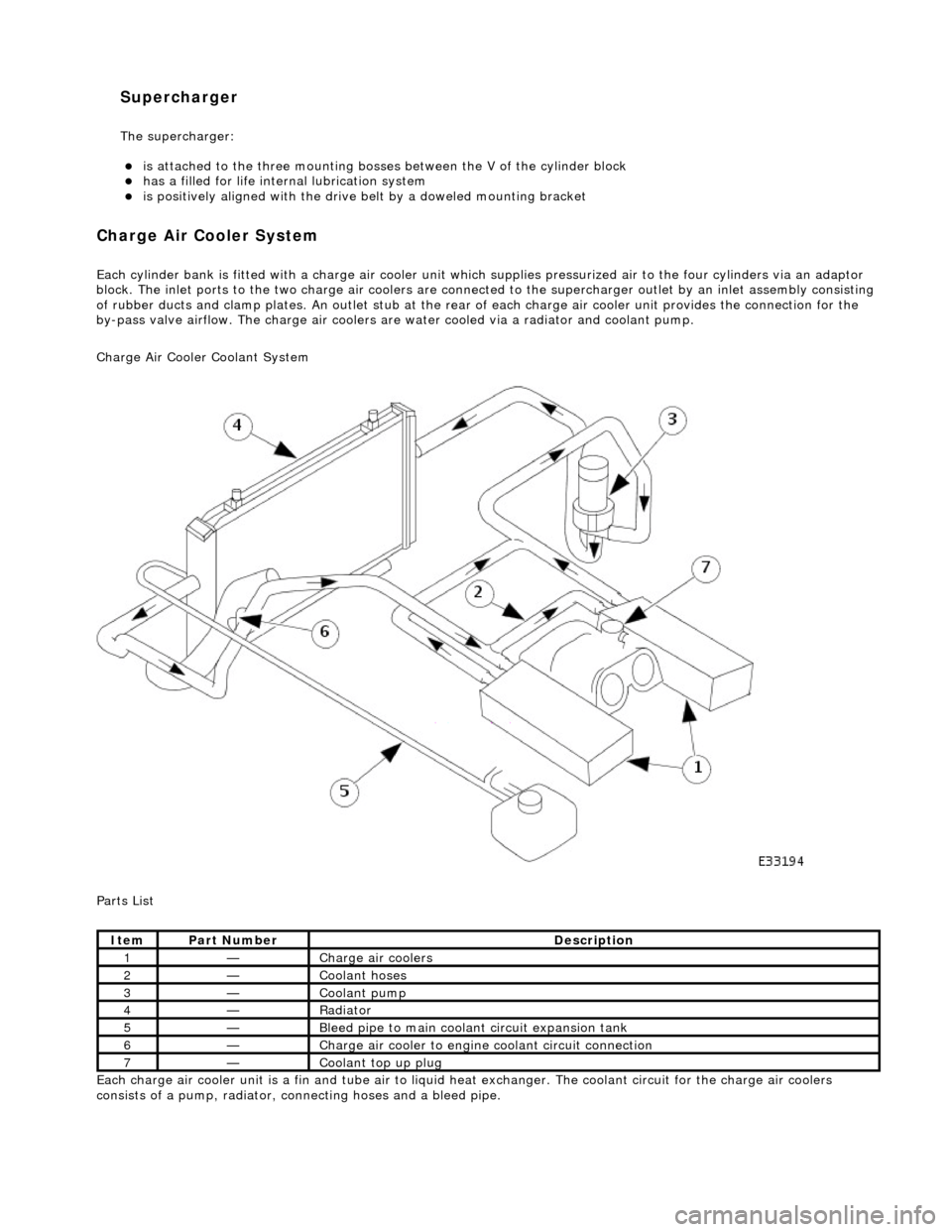
harge Air Cooler System
Each cyl
inder bank is fitted with a charge air cooler unit wh
ich supplies pressurized air to the four cylinders via an adaptor
block. The inlet ports to the tw o charge air coolers are connected to the supercharger outlet by an inle t assembly consisting
of rubber ducts and clamp plates . An outlet stub at the rear of each charge air cooler unit provides the connection for the
by-pass valve airflow. The charge air coolers ar e water cooled via a radiator and coolant pump.
Charge Air Cooler Coolant System
Parts List
Each charge air cooler unit is a fin and tube air to liquid heat exchanger. The coolant circuit for the charge air coolers
consists of a pump, ra diator, connecting hoses and a bleed pipe.
It
em
Par
t Number
De
scription
1—Charge air cool
ers
2—Coo
lant hoses
3—Coo
lant pump
4—Radi
ator
5—Ble
ed pipe to main coolant circuit expansion tank
6—Charge air cooler to en
gine
coolant circuit connection
7—Coo
lant top up plug
Supercharger
The supe
rcharger: