Page 1019 of 2490
C
harge Air Cooler Adaptors
The charge
air cooler adaptors:
provi
de the interface between the charge air coolers and the cylinder heads
l
ocate the fuel ra
ils and injectors
For removal and installation refer to section 303-01.
Fuel R
ails
The plasti
c fuel rails locate in
the charge air cooler adaptors:
Bank 2 fuel rai
l has the fuel feed pipe attached at the rear
of the engine and the fuel cross-over pipe at the front
Bank 1 fuel rai
l connects to
the other side of the cross-over pipe at the front of the engine and the fuel return pipe /
pressure regulato r at the rear
Fuel C
ross-over Pipe
The fu
el cross-over pipe connects the fuel rails together but is not interchangeable between the normally aspirated engine
and the supercha rged version.
Page 1037 of 2490
Fuel Ch
arging and Controls
- Fuel Injector4.0L NA V8 - AJ27/3.2L NA V8 -
AJ26
Re
moval and Installation
Remov
al
S
pecial Tool(s)
R
emover - Fuel Injector
303-539 (JD 231)
1. Disconnect battery ground cable (IMPORTANT, see SRO
86.15.19 for further information).
2. WARNING: BEFORE PROCEEDING, IT IS ESSENTIAL THAT
THE WARNING NOTES GIVEN IN SECTION 100-00 (UNDER THE
HEADING 'SAFETY PRECAUTIONS') ARE READ AND
UNDERSTOOD.
Depressurize the fuel sy stem; refer to 19.50.02.
3. R
emove engine covers.
4. Di
sconnect bank 1 or 2 inject
or connectors and reposition
harness to allow access to injectors.
5. Remove bolts which secure fuel injector clamp plate to inlet
manifold.
Page 1039 of 2490

Fuel Charging and Controls
- Fuel Injector4.0L SC V8 - AJ26
Rem
oval and Installation
Remov
al
Installation
1.
Disconnect battery ground cabl e (IMPORTANT, see SRO 86.15.19
for further information).
2. WARNING: BEFORE PROCEEDING, IT IS ESSENTIAL THAT
THE WARNING NOTES GIVEN IN SECTION 100-00 (UNDER THE
HEADING 'SAFETY PRECAUTIONS') ARE READ AND UNDERSTOOD.
Depressurize fuel system; refer to 19.50.02.
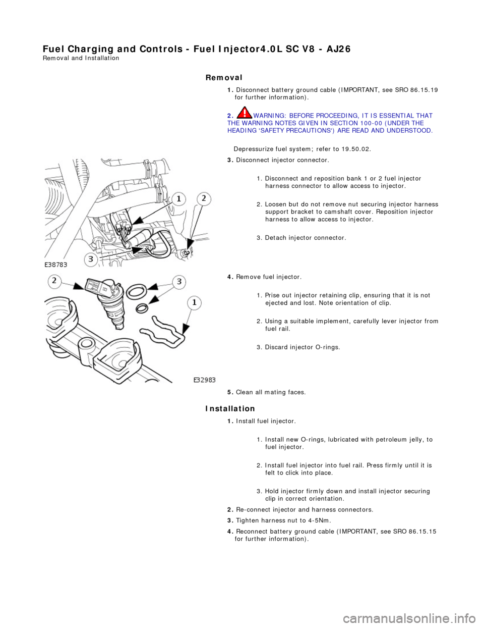
3.
Disconnect injector connector.
1. Disconnect and reposition bank 1 or 2 fuel injector harness connector to allow access to injector.
2. Loosen but do not remove nut securing injector harness support bracket to camshaft cover. Reposition injector
harness to allow access to injector.
3. Detach injector connector.
4.
Remove fuel injector.
1. Prise out injector retaining clip, ensuring that it is not ejected and lost. Note orientation of clip.
2. Using a suitable implement, carefully lever injector from
fuel rail.
3. Discard injector O-rings.
5. Clean all mating faces.
1. Install fuel injector.
1. Install new O-rings, lubricat ed with petroleum jelly, to
fuel injector.
2. Install fuel injector into fuel rail. Press firmly until it is felt to click into place.
3. Hold injector firmly down and install injector securing clip in correct orientation.
2. Re-connect injector and harness connectors.
3. Tighten harness nut to 4-5Nm.
4. Reconnect battery ground cable (IMPORTANT, see SRO 86.15.15
for further information).
Page 1040 of 2490

Fuel Char
ging and Controls - Fu
el Injectors4.0L SC V8 - AJ26
Remo
val and Installation
Remov
a
l
Installation
1. Disc onne
ct battery ground cable (IMPORTANT, see SRO
86.15.19 for further information).
2. WARNING: BEFORE PROCEEDING, IT IS ESSENTIAL THAT
THE WARNING NOTES GIVEN IN SECTION 100-00 (UNDER THE
HEADING 'SAFETY PRECAUTIONS') ARE READ AND
UNDERSTOOD.
Depressurize fuel syst em; refer to 19.50.02.
3. Drain radiator coolant; refer to 2
6.10.01.
4. Remove air cleaner cover / inta ke assembly; refer 19.10.30.
5. Remove throttle body; refer to 19.70.04.
6. Remove throttle induction elbo w; refer to (SC) 19.70.28.
7. Remove exhaust gas re-circulation valve (EGR) if fitted; refer
to 17.45.01.
8. Remove supercharger outlet duct and gasket; refer to
18.50.16.
9. Remove coolant outlet pipe; refer to (SC) 26.31.08 .
10. Remove supercharger drive belt; refer to 18.50.08.
11. Remove supercharger assembly; refer to 18.50.15.
12. Remove bank 1 or 2 charge air cooler as required; refer to
18.50.18 and / or 18.50.19.
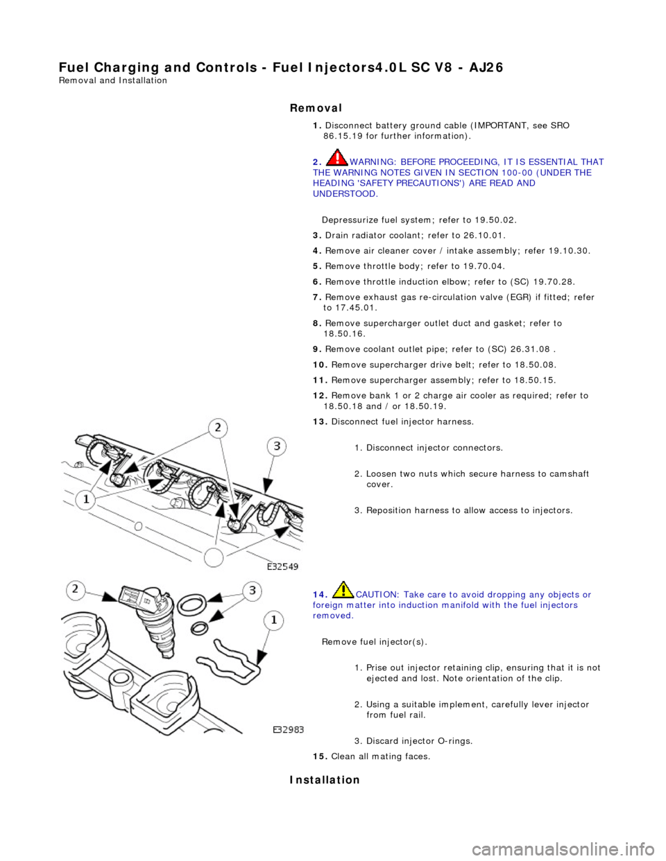
13 . Di
sconnect fuel injector harness.
1. Disconnect injector connectors.
2. Loosen two nuts which se cure harness to camshaft
cover.
3. Reposition harness to al low access to injectors.
14. CAUTI
ON: Take care to avoi
d dropping any objects or
foreign matter into induction ma nifold with the fuel injectors
removed.
Remove fuel injector(s). 1. Prise out injector retaining clip, ensuring that it is not
ejected and lost. Note orientation of the clip.
2. Using a suitable implemen t, carefully lever injector
from fuel rail.
3. Discard injector O-rings.
15 . Cle
an all mating faces.
Page 1049 of 2490

Accessory Drive - Accessory Drive
Description an
d Operation
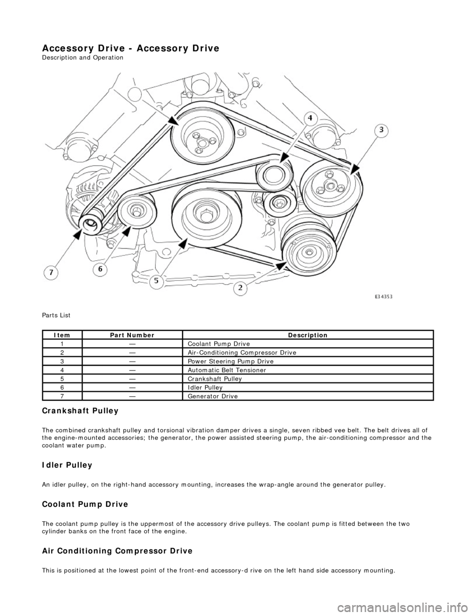
Parts List
Cran
kshaft Pulley
The combined crankshaft
pulley and torsio
nal vibration damper drives a single, seve n ribbed vee belt. The belt drives all of
the engine-mounted accessories; the generator, the power assi sted steering pump, the air-conditioning compressor and the
coolant water pump.
I
dler Pulley
An i
dler pulley, on the right-hand
accessory mounting, increases the wrap-angle around the generator pulley.
Coolant Pump Drive
The coolan
t pump pulley is the
uppermost of the accessory drive pulleys. Th e coolant pump is fitted between the two
cylinder banks on the front face of the engine.
Air Conditioning Compressor Drive
Thi
s is positioned at the lowest poin
t of the front-end accessory-d rive on the left hand side accessory mounting.
It
em
Par
t Number
De
scription
1—Coo
lant Pump Drive
2—Ai
r-Conditioning Compressor Drive
3—Power Steer
ing Pump Drive
4—Au
tomatic Belt Tensioner
5—Crankshaft Pul
ley
6—Idle
r Pulley
7—Generator Dri
ve
Page 1072 of 2490
Engine Ignition -
General Spe
cifications
Torque Specifications
Ite
m / Model
Sp
ecification
F
i
ring Order (cylinder - bank)
1-
1
, 1-2, 4-1, 2-1, 2-2, 3-1, 3-2, 4-2
Spark P
l
ug Type
(Leaded markets -
service fit only)NGK BK
R5E-11
N
ormal
ly Aspirated
NG
K PF
R5G-11E
SuperchargedNG
K PF
R6G-13E
Spark P
l
ug Gap
mm
(i
n)
(Leaded markets -
service fit only)1.0 -
1.1 (0.039 - 0.043)
N
ormal
ly Aspirated
1.
0 -
1.1 (0.039 - 0.043)
Supercharged1.
2 -
1.3 (0.047 - 0.051)
High
Tem
perature Nickel Anti-Seize
Lubricant (Spark Plug Thread)
'Ne
verseez' (ESE-M12A4-A)
Com
p
onent
Nm
Spark P
l
ugs
25
-
29
Coil
on
Plug Bolts
4 -
6
Co
il
Cover Bolts
4 -
6
Page 1073 of 2490

Engine Igni
tion -
Engine Ignition
Description an
d Operation
I
gnition coil and spark plug reference
Any positional r
eferences are base
d upon the following convention:
viewing from the driving position, the right-hand cylinder bank is designated bank 1 (A on circuit diagrams) and the left-
hand cylinder bank as bank 2 (B on circuit diagrams).
The cylinder bores of each bank are number ed 1 to 4, from the front of the vehicle.
Ig
nition System
Th
e ignition system provides timing cont
rol in accordance with the engine mana gement strategy and powertrain sensor
inputs; the system consists of:
engine
control module
igni
tion coils supply relay
ignit
ion control modules
igni
tion coils
spark plu
gs
Engine Control Module (ECM)
pr
ovides triggering for the ignition control modules
to control individual firing of the spark plugs
supplies ground for
the igni
tion coils supply relay
I
gnition Coils Supply Relay
The
ignition coils supply relay is located
in the engine and transmission control mo dule compartment; refer to Relay Details
in Electrical Wiring and Circuit Protection, Section 418-01.
The ECM switches a ground to the coil of the ignition coils supply relay; the relay energizes and switches a 12v supply to the
ignition control modules and the ignition coils.
I
gnition Control Modules
Page 1074 of 2490
T w
o ignition control modules control firing of the spark plug
s when triggered by the engine control module (ECM); the
modules provide an interface between the ECM and the coil on plugs such that:
Ignition cont
rol module 1 drives bank 1 -
coils 1 and 4, bank 2 - coils 2 and 3.
Ignition cont
rol module 2 drives bank 1 -
coils 2 and 3, bank 2 - coils 1 and 4.
Ite
m
Par
t
Number
De
scr
iption
1—Ignition control
module 1
2—Ignition control module 2