Page 886 of 2490

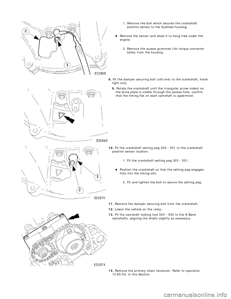
1. Remove the bolt which secures the crankshaft position sensor to the flywheel housing.
Remove the sensor and allow it to hang free under the
engine.
2. Remove the access grommet (for torque converter bolts) from the housing.
8. Fit the damper securing bolt (old one) to the crankshaft, hand-
tight only.
9. Rotate the crankshaft until the triangular arrow indent on
the drive plate is visible thro ugh the access hole; confirm
that the timing flat on ea ch camshaft is uppermost.
10. Fit the crankshaft setting peg 303 - 531 to the crankshaft
position sensor location.
1. Fit the crankshaft setting peg 303 - 531.
Position the crankshaft so that the setting peg engages
fully into the timing slot.
2. Fit and tighten the bolt to secure the setting peg.
11. Remove the damper securing bolt from the crankshaft.
12. Lower the vehicle on the ramp.
13. Fit the camshaft locking tool 303 - 530 to the A-Bank
camshafts, aligning the shafts slightly as necessary.
14. Remove the primary chain tens ioner. Refer to operation
12.65.54, in this Section
Page 889 of 2490

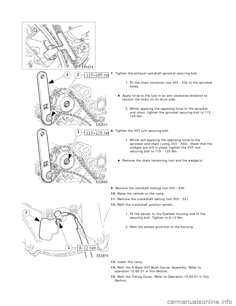
7. Tighten the exhaust camshaft sprocket securing bolt.
1. Fit the chain tensioner tool 303 - 532 to the sprocket holes.
Apply force to the tool in an anti-clockwise direction to
tension the chain on its drive side.
2. Whilst applying the opposing force to the sprocket and chain, tighten the sprock et securing bolt to 115 -
125 Nm.
8. Tighten the VVT unit securing bolt.
1. Whilst still applying the opposing force to the
sprocket and chain (using 303 - 532), check that the
wedges are still in place, tighten the VVT unit
securing bolt to 115 - 125 Nm.
Remove the chain tensioning tool and the wedge(s).
9. Remove the camshaft locking tool 303 - 530.
10. Raise the vehicle on the ramp.
11. Remove the crankshaft setting tool 303 - 531.
12. Refit the crankshaft position sensor.
1. Fit the sensor to the fl ywheel housing and fit the
securing bolt. Tighten to 8-12 Nm.
2. Refit the access grommet to the housing.
13. Lower the ramp.
14. Refit the A-Bank VVT Bush Carrier Assembly. Refer to
operation 12.65.51 in this Section.
15. Refit the Timing Cover. Refer to Operation 12.65.01 in this
Section.
Page 898 of 2490

ENSURE THAT ALL FIRE PREVENTION PROCEDURES ARE ACTIVE.
BEFORE PROCEEDING, IT IS ESSENTIAL THAT THE WARNING NOTES GIVEN IN SECTION 100-00 (UNDER THE
HEADING 'SAFETY PRECAUTIONS') ARE READ AND UNDERSTOOD.
9. Depressurise the fuel system.
Ensure that the ignition is switched off and remove the
valve cap from the fuel cross-over pipe. Place a cloth
under the valve to collect any spillage.
Place a closed container, su itable for collecting fuel,
adjacent to the vehicle. Remove the lid.
10. Connect the fuel injection pressure test equipment 310 - 058
(or other suitable type). Insert the drain / bleed tube into the
fuel container. Follow the ma nufacturer's instructions and
depressurise the fuel system.
11. Store the drained fuel safely and ensure that the lid is closed
securely. Remove the equipmen t and discard the cloth from
beneath the valve. Refit the valve cap.
12. Disconnect the breather pipe from the A-Bank camshaft
cover.
1. Disconnect the breather pipe from the stub pipe.
2. Remove and discard the O-ring seal from the breather
pipe.
13. Disconnect the air flow meter multi-plug.
14. Cut and remove the strap which secures the vacuum pipe to
the induction elbow.
15. Disconnect the intake tube from the throttle body.
1. Remove the two bolts which secure the intake tube to the throttle body.
2. Disconnect the intake tube from the throttle body.
Page 914 of 2490
Repeat
the above procedure for the other side.
16 . Connect
the driveshaft (propshaft
) flange to the transmission
output flange.
F i
t the three bolts which secure the flange.
17 . F
it the downpipe catalytic converters.
1. Fit a new gasket to the downpipe flange and fit the
downpipe assembly. to the manifold.
F i
t the bolts which secure
the downpipe to the lower
mounting bracket.
Repeat the above operation
s
for the other downpipe
catalytic converter.
18 . F
rom above the vehicle, tighte
n the manifold flange nuts, A-
Bank and B-Bank flanges, to the correct torque.
19. Fit the front muffler assembly.
Locate the front muf fler into the
downpipe catalytic
converters.
20. Move the front muffler forwar d to allow the intermediate
mufflers to be connected.
Page 922 of 2490
to th
e throttle body.
51 . Co
nnect the intake tube to the throttle body.
1. Fit a new seal and connect the intake tube to the throttle body.
2. Fit the two bolts which secure the intake tube to the throttle body.
52 . Conne
ct the air cleaner cover.
F
it
the five clips which secu
re the air cleaner cover.
53 . Re
connect the breather pipe to the A-Bank camshaft cover.
1. Fit a new O-ring seal to the breather pipe.
2. Connect the breather pipe to the stub pipe.
54. Connect the air flow meter connector.
55. Fit a new Ty-strap to secures the vacuum pipe to the
induction elbow.
56. Refill the cooling system. Refer to Operation 26.10.01.
57. NOTE: When the engine is star ted from cold and run for a
short period only, before being swit ched off, a quantity of oil will
Page 924 of 2490

Engine Cooling
- Engine Cooling
Descr
i
ption and Operation
Engine Cooling Comp onents - Normally Aspirated Vehicles
Engine cooling is via a low volume, high velocity system which achieves a very fast warm up. The temperature of the
combustion chambers is reduced along with a more even temperature distribution. The temperature of the bores is increased.
F r
om the pump, coolant flows into each bank of the cylinder bl
ock. In each bank, approximately 50% of the coolant cools the
cylinder bores and the remainder is diverted th rough the bypass gallery to the cylinder head.
With the thermostat closed, coolant returns directly to the pump through the bypass on the thermostat housing.
With the thermostat open, coolant returns to the pump via the radiator.
The cooling system uses a mixture of water and Jaguar Anti-Freeze/Inhibitor (Dow 542).
The cooling system on a supercharged engine is similar, but has additional components for cooling the intake air.
Engine Cooling Co mponents - Supercharged Vehicles
ItemDescrip
tion
1Thr
ottle B
ody
2Hea
ter Return
3Coolant Pum p
4Ther
mostat Housing
5Vehicle Radia
t
or
6Hea
ter Su
pply
7Bleed
Outl
et (to expansion tank)
8EGR V
a
lve (when fitted)
9Bleed
Outl
et (to expansion tank)
Page 925 of 2490

T
he cooling system for the supercharged engine is very similar
to the normally aspirated engine, but with the addition of a
water cooled, intake air charge cooling system. This comprises a radiator, an electrically operated water pump and two
charge air cooler assemblies (heat exchangers) - one for each bank. The system works independently, but is connected to the
main cooling system at the bottom hose to allow for therma l expansion and to help to prevent unwanted circulation.
The condenser for the air conditioning system fits between th e coolant main radiator and the charge air cooling system
radiator.
Cylinder Block Heater, Drain Location
ItemDe
scription
1Rad
iator - Intake Air Coolant
2Ele
ctrically Operated Coolant Pump
3Top Hose
4Charge Air Coo
lers -
Intake Air Cooling
5Fi
lling Point for Intake Air Cooling
6N
on-Return Valves - Heater
7Ele
ctrically Operated Coolant Pump
8Hea
ter Matrix
9Wate
r Valve - Heater Control
10EGR V
alve (when fitted)
11Thr
ottle Body
12Coolan
t Recovery Bottle
13H
eader/Expansion Tank
14Eng
ine Coolant Pump
15The
rmostat Housing
16Bottom
Hose
17Air Bleed
Pipes
18Rad
iator - Main Cooling System
Page 926 of 2490
A coola n
t drain plug is located at the rear of the cylinder block.
Coolant may be drained from the A-bank, by removing the coolant pipe from behind the starter motor.
For vehicles fitted with the cold climate package, a cylinder block heater (shown) replaces the drain plug located on the B-
bank.
Coolant Pump and Flow Control
The coolant pump is fitted between the two cylinder banks, on the front face of the cylinder block.
The pump consists of a housing containing a shaft, with a sh rouded plastic impeller on one end and a drive pulley on the
other.
A pair of roller bearings support the shaft in the housing. A seal behind the impeller prevents coolant from contaminating the
bearings. Should this seal fail, coolant escapes from a witness hole in the housin g indicating that immediate action is
required.
An O-ring and an aluminum-alloy gasket, seal the ports between the pump and the cylinder banks.
Coolant Outlet Duct