Page 2175 of 2490
Installation
12. Disconnect seat motor and squab heater harness multiplugs.
13. Slacken and remove four bolts securing seat frame to floor
and remove seat from vehicle.
1. Position seat in vehi cle and fit but do not tighten four bolts
securing frame to floor.
2. Fit and fully tighten the two bolt s securing squab frame to rear
panel.
3. Fully tighten bolts securing frame to floor.
4. Connect seat motor and squab heater harness multiplugs.
5. Position side trim panel and carefully pass seat belt lower
anchor through escutcheon and trim aperture.
6. Fit and tighten seat belt anchor securing bolt.
7. Position side trim and push do wnwards to engage keyhole on
squab outer fixing.
8. Position trim lower end over st ud and fit and fully seat new
scrivet.
9. Position seat cushion for access and connect cushion heater
harness multiplug.
10. Push seat cushion rearwards to engage it in rear securing
lugs.
Page 2176 of 2490
11.
Fit and tighten cushion front securing bolts and nuts.
12. Connect ground cable to batt ery terminal and fit battery
cover. Refer to 86.15.15.
13. Return seat to original position.
Page 2178 of 2490
Installation
1. Install and fully seat switchpack in seat mounting.
2. Raise cushion pad for access to rear of switchpack and connect
harness multiplug.
3. Release cushion pad and secure cushion cover front elastic
retaining straps to seat frame.
4. Pull cushion cover over cushion pad and fully seat edge
retaining strip on seat frame.
5. Install seat in vehicle. Refer to 76.70.01.
6. Connect ground cable to battery terminal and fit battery cover.
Refer to 86.15.15.
Page 2181 of 2490
Glass, Frames and Mechanisms - Door Window Control Switch Bulb
Removal and Installation
Removal
1. Remove casing/armrest asse mbly from door. Refer to
76.34.01.
2. Slacken and remove armres t front securing screw
3. Position armrest for access, slacken and remove two
switchpack securing screws and remove switchpack assembly from armrest.
4. Invert switchpack and using a small flat bladed screwdriver
rotate bulb holder 1/8 turn counterclockwise.
5. Remove bulb from switchpack base.
Page 2183 of 2490
Glass, Frames and Mechanisms - Front Door Window Glass
Removal and Installation
Removal
Installation
1. Remove battery cover and disc onnect ground cable from
battery terminal. Refer to 86.15.19.
2. Remove front door casing. Refer to 76.34.01.
3. Remove water shedder carefu lly guiding harness through
penetration, and place adhesive face down on clean polythene
sheet.
4. Position PVC weathe rshield for access.
5. Remove front door modu le. Refer to 86.80.34.
6. Remove front door glass lift motor and regulator assembly.
Refer to 86.25.04.
7. Supporting glass, remove tape securing it to top of door for
motor removal.
8. Withdraw glass upwards through aperture and out via outboard side of frame.
1. Position glass in frame aperture.
2. Locate leading edge of glass in seal of front channel.
3. Carefully slide glass into position, ensuring that seals are not
deformed into channels.
Page 2184 of 2490
4.
Fully raise glass and using linen tape, secure to top of door
frame.
5. Fit door glass lift motor. Refer to 86.25.04.
6. Fit door module. Refer to 86.80.34.
7. Reposition PVC inne r weathershield.
8. Position water shedder and carefully pass harness multiplugs
through penetration.
9. Ensuring door mating surfaces ar e clean and dry, firmly seat
water shedder.
10. Fit door casing. Refer to 76.34.01.
11. Connect ground cable to batter y terminal and fit cover to
battery. Refer to 86.15.15.
Page 2186 of 2490
Glass, Frames and Mechanisms - Front Door Window Regulator and Motor
Removal and Installation
Removal
1. Ensure that door glass is in fully up position.
2. Remove battery cover and disc onnect ground cable from
battery terminal. Refer to 86.15.19.
3. Remove casing/armrest asse mbly from door. Refer to
76.34.01.
4. Remove water shedder carefu lly guiding harness through
penetration, and place adhesive face down on clean polythene
sheet.
5. Position PVC inner weat hershield for access.
6. Remove front door modu le. Refer to 86.80.34.
7. Using linen tape, secure to p of glass to door frame.
8. Disconnect harness mult iplug from lift motor.
9. Slacken and remove screws and nuts securing lift motor to
door.
10. Mark position of door glass gu ide securing screws and slacken and remove screws.
11. Separate motor/regulator assembly from glass, lower into
bottom of door and remove assembly from door.
Page 2187 of 2490

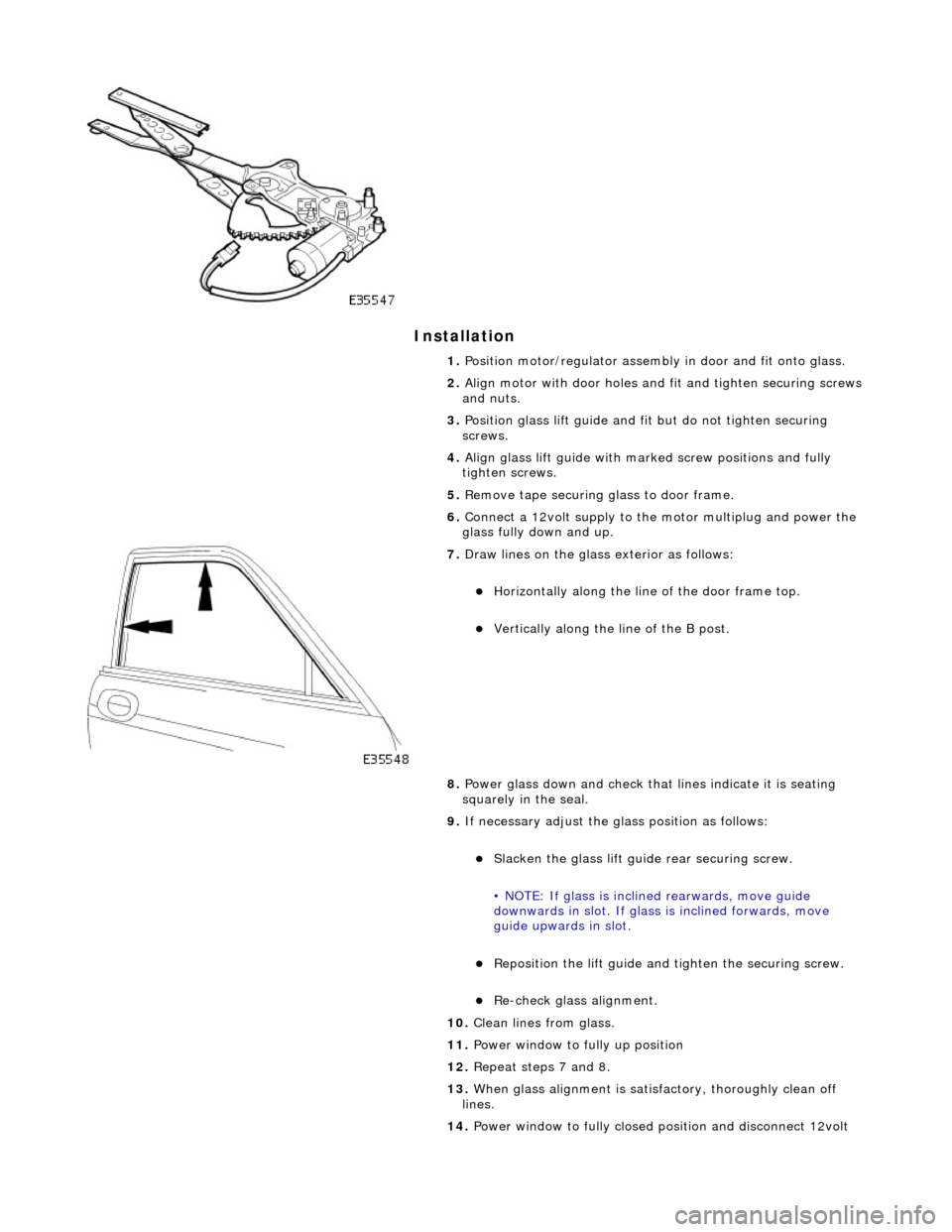
Installation
1. Position motor/regulator assembly in door and fit onto glass.
2. Align motor with door holes and fit and tighten securing screws
and nuts.
3. Position glass lift guide and fi t but do not tighten securing
screws.
4. Align glass lift guide with marked screw positions and fully
tighten screws.
5. Remove tape securing glass to door frame.
6. Connect a 12volt supply to the motor multiplug and power the
glass fully down and up.
7. Draw lines on the glass exterior as follows:
Horizontally along the line of the door frame top.
Vertically along the line of the B post.
8. Power glass down and check that lines indicate it is seating
squarely in the seal.
9. If necessary adjust the glass position as follows:
Slacken the glass lift guid e rear securing screw.
• NOTE: If glass is inclin ed rearwards, move guide
downwards in slot. If glass is inclined forwards, move
guide upwards in slot.
Reposition the lift guide and tighten the securing screw.
Re-check glass alignment.
10. Clean lines from glass.
11. Power window to fully up position
12. Repeat steps 7 and 8.
13. When glass alignment is satisf actory, thoroughly clean off
lines.
14. Power window to fully closed po sition and disconnect 12volt