Page 1575 of 3573
ENGINE MECHANICAL 6A Ð 25
CRANKSHAFT
DISASSEMBLY
1. Cylinder Head
·Refer to ÒCylinder headÓ in Section 6A2.
2. Camshaft Timing Gear
·Refer to ÒCamshaftÓ in Section 6A2.
3. Crankshaft Timing Gear
4. Crankshaft Front Oil Seal
5. Timing Gear Case
6. Flywheel
7. Cylinder Block Rear Plate
Page 1581 of 3573

ENGINE MECHANICAL 6A Ð 31
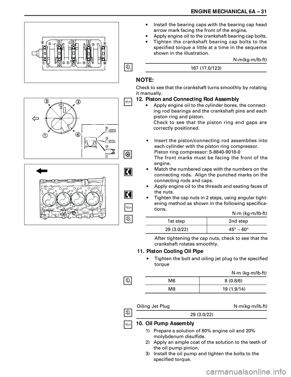
·Install the bearing caps with the bearing cap head
arrow mark facing the front of the engine.
·Apply engine oil to the crankshaft bearing cap bolts.
·Tighten the crankshaft bearing cap bolts to the
specified torque a little at a time in the sequence
shown in the illustration.
NOTE:
Check to see that the crankshaft turns smoothly by rotating
it manually.
12. Piston and Connecting Rod Assembly
·Apply engine oil to the cylinder bores, the connect-
ing rod bearings and the crankshaft pins and each
piston ring and piston.
Check to see that the piston ring end gaps are
correctly positioned.
29 (3.0/22)
N·m(kg·m/lb.ft) Oiling Jet Plug
10. Oil Pump Assembly
1) Prepare a solution of 80% engine oil and 20%
molybdenum disulfide.
2) Apply an ample coat of the solution to the teeth of
the oil pump pinion.
3) Install the oil pump and tighten the bolts to the
specified torque.After tightening the cap nuts, check to see that the
crankshaft rotates smoothly.
11. Piston Cooling Oil Pipe
·Tighten the bolt and oiling jet plug to the specified
torque ·Insert the piston/connecting rod assemblies into
each cylinder with the piston ring compressor.
Piston ring compressor: 5-8840-9018-0
The front marks must be facing the front of the
engine.
·Match the numbered caps with the numbers on the
connecting rods. Align the punched marks on the
connecting rods and caps.
·Apply engine oil to the threads and seating faces of
the nuts.
·Tighten the cap nuts in 2 steps, using angular tight-
ening method as shown in the following specifica-
tions.
167 (17.0/123)N·m(kg·m/lb·ft)
N·m (kg·m/lb·ft)
45¡ ~ 60¡ 1st step 2nd step
29 (3.0/22)
N·m (kg·m/lb·ft)
19 (1.9/14) M6 8 (0.8/6)
M8
Page 1583 of 3573
ENGINE MECHANICAL 6A Ð 33
2) Tighten the timing gear case bolt together with
the timing gear case gasket to the specified
torque.
19 (1.9/14)N·m(kg·m/lb·ft)
3) Cut away the gasket protruding above the fitting
surfaces (as shown in the illustration).
4. Crankshaft Front Oil Seal
·Use the installer to install the front oil seal 1 to
the gear case cover 2.
Oil Seal Installer: 5-8840-2061-0
Note the oil seal installation depth 3 shown in
the illustration.
Depth 3 = 1 mm (0.0394 in.)
3. Crankshaft Timing Gear
Use the crankshaft timing gear installer 1 to install the
timing gear 2.
The crankshaft timing mark (ÒX Ð XÓ) must be facing
outward.
Crankshaft Timing Gear Installer: 5-8522-0024-0
2. Camshaft Timing Gear
·Tighten the fixing bolt to the specified torque.
64 (6.5/47)N·m(kg·m/lb·ft)
1. Cylinder Head
·Refer to ÒCylinder headÓ in Section 6A2.
Page 1584 of 3573
6A Ð 34 ENGINE MECHANICAL
PISTON AND CONNECTING ROD
DISASSEMBLY
1. Cylinder Head Assembly
·Refer to ÒCylinder headÓ in Section 6A2.
2. Crankcase Assembly
·Refer to ÒCrankcaseÓ in Section 6A2
3. Oil Pump Assembly
4. Connecting Rod Bearing Cap
5. Piston and Connecting Rod
·Remove carbon deposits from the upper portion
of the cylinder wall with a scraper before
removing the piston and connecting rod
Page 1585 of 3573
ENGINE MECHANICAL 6A Ð 35
6. Piston Ring
Remove the piston rings with a piston ring expander.
Arrange the removed piston rings in the cylinder
number order.
7. Piston Pin Snap Ring
·Use a pair of pliers to remove the piston pin snap
rings
8. Piston Pin
NOTE:
Keep the parts removed from each cylinder separate. All
parts must be reinstalled in their original positions.
9. Piston
10. Connecting Rod
INSPECTION AND REPAIR
PISTON AND PISTON RING
Pistons
Carefully clean away all the carbon adhering to the piston
head and the piston ring grooves.
NOTE:
Never use a wire brush to clean the pistons. Damage will
result.
Visually check each piston for cracking, scoring, and other
signs of excessive wear.
If any of the above conditions are present, the piston
must be replaced.
Piston Diameter
1. Measure the piston outside diameter with micrometer
at the piston grading position.
71.00 (2.7974)
mm(in) Piston Grading Position
Page 1591 of 3573
ENGINE MECHANICAL 6A Ð 41
5. Piston and Connecting Rod
·Apply engine oil to the cylinder bores, the
connecting rod bearings and the crankshaft pins.
·Check to see that the piston ring end gaps are
correctly positioned.
·Insert the piston/connecting rod assemblies into
each cylinder with the piston ring compressor.
·The front marks must be facing the front of the
engine.
4. Connecting Rod Bearing Cap
·Apply engine oil to screw and seat of bearing cap
bolts and nuts.
·Tighten the cap nuts in 2 steps, using angular
tightening method as shown in the following
specifications.
N·m (kg·m/lb·ft)
45¡ ~ 60¡ 1st step 2nd step
29 (3.0/22)
After tightening the cap nuts, check to see that the
crankshaft rotates smoothly.
3. Oil Pump Assembly
2. Crankcase Assembly
·Refer to ÒCrankcaseÓ in Section 6A2.
1. Cylinder Head Assembly
·Refer to ÒCylinder headÓ in Section 6A2.
Page 1592 of 3573
6A Ð 42 ENGINE MECHANICAL
CYLINDER BLOCK
DISASSEMBLY
1. Cylinder Head Assembly
·Refer to ÒCylinder headÓ in Section 6A2.
2. Cylinder Head Gasket
3. Flywheel
4. Cylinder Block Rear Plate
5. Crankshaft Rear Oil Seal
·With the oil seal pushed in deep, install the special
tool as shown in the illustration and remove the oil
seal.
Oil Seal Remover : 5-8840-2362-0
6. Crankcase Assembly
·Refer to ÒCrankcaseÓ in Section 6A2
7. Oil Pump Assembly
Page 1598 of 3573

6A Ð 48 ENGINE MECHANICAL
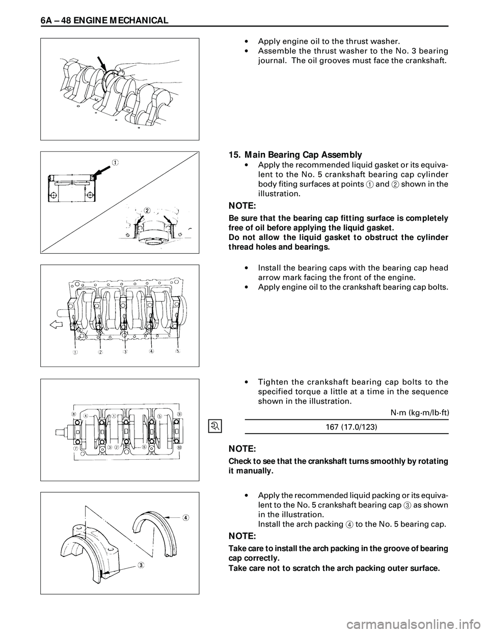
·Apply engine oil to the thrust washer.
·Assemble the thrust washer to the No. 3 bearing
journal. The oil grooves must face the crankshaft.
15. Main Bearing Cap Assembly
·Apply the recommended liquid gasket or its equiva-
lent to the No. 5 crankshaft bearing cap cylinder
body fiting surfaces at points 1 and 2 shown in the
illustration.
NOTE:
Be sure that the bearing cap fitting surface is completely
free of oil before applying the liquid gasket.
Do not allow the liquid gasket to obstruct the cylinder
thread holes and bearings.
·Install the bearing caps with the bearing cap head
arrow mark facing the front of the engine.
·Apply engine oil to the crankshaft bearing cap bolts.
·Tighten the crankshaft bearing cap bolts to the
specified torque a little at a time in the sequence
shown in the illustration.
NOTE:
Check to see that the crankshaft turns smoothly by rotating
it manually.
·Apply the recommended liquid packing or its equiva-
lent to the No. 5 crankshaft bearing cap 3 as shown
in the illustration.
Install the arch packing 4 to the No. 5 bearing cap.
NOTE:
Take care to install the arch packing in the groove of bearing
cap correctly.
Take care not to scratch the arch packing outer surface.
167 (17.0/123)N·m (kg·m/lb·ft)