Page 1520 of 3573
00 Ð 20 SERVICE INFORMATION
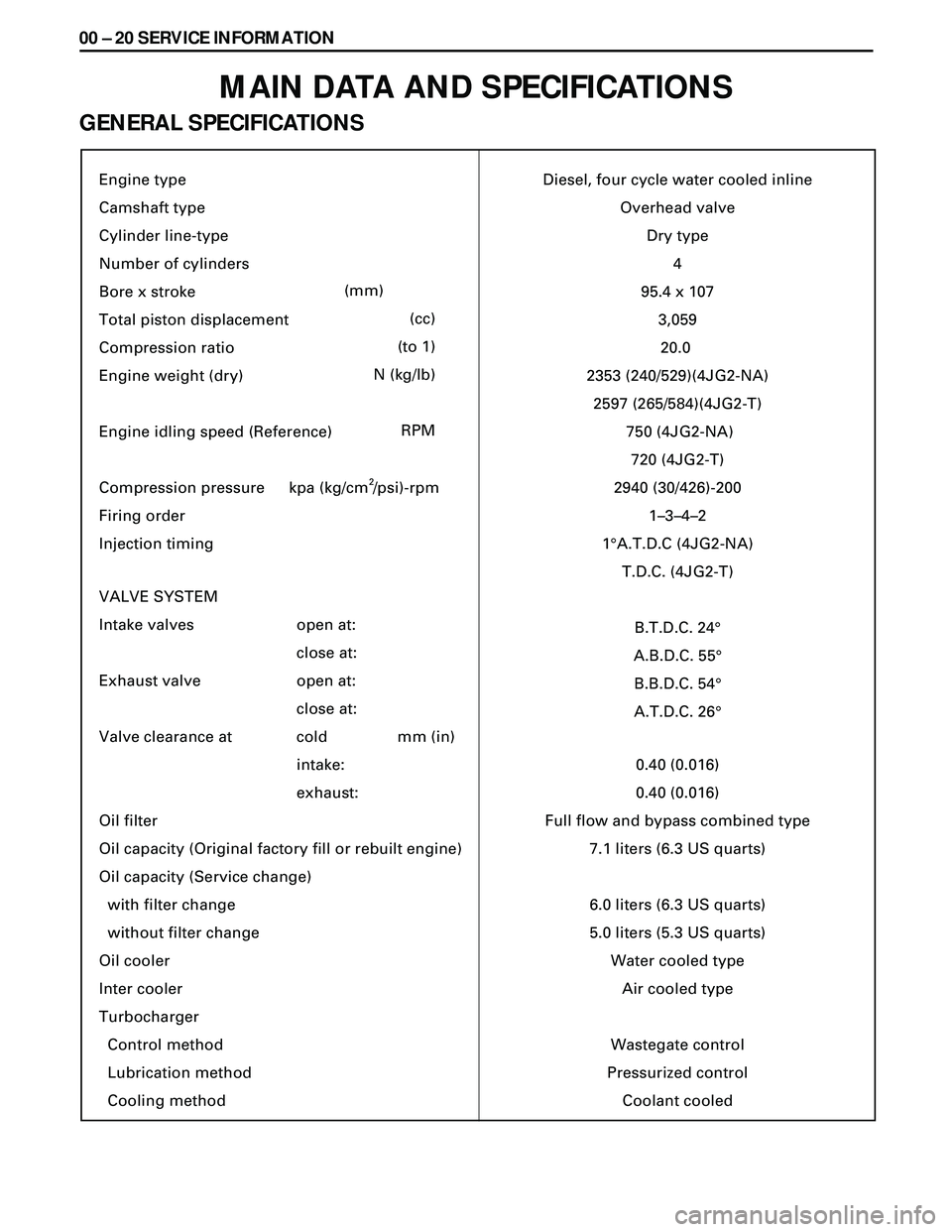
MAIN DATA AND SPECIFICATIONS
GENERAL SPECIFICATIONS
Engine type
Camshaft type
Cylinder line-type
Number of cylinders
Bore x stroke
Total piston displacement
Compression ratio
Engine weight (dry)
Engine idling speed (Reference)
Compression pressure
Firing order
Injection timing
VALVE SYSTEM
Intake valves
Exhaust valve
Valve clearance at
Oil filter
Oil capacity (Original factory fill or rebuilt engine)
Oil capacity (Service change)
with filter change
without filter change
Oil cooler
Inter cooler
Turbocharger
Control method
Lubrication method
Cooling method
(mm)
(cc)
(to 1)
N (kg/lb)
RPM
open at:
close at:
open at:
close at:
cold
intake:
exhaust:mm (in)Diesel, four cycle water cooled inline
Overhead valve
Dry type
4
95.4 x 10⁷
3,059
20.0
2353 (240/529)(4JG2-NA)
2597 (265/584)(4JG2-T)
750 (4JG2-NA)
720 (4JG2-T)
2940 (30/426)-200
1–3–4–2
1¡A.T.D.C (4JG2-NA)
T.D.C. (4JG2-T)
B.T.D.C. 24¡
A.B.D.C. 55¡
B.B.D.C. 54¡
A.T.D.C. 26¡
0.40 (0.016)
0.40 (0.016)
Full flow and bypass combined type
7.1 liters (6.3 US quarts)
6.0 liters (6.3 US quarts)
5.0 liters (5.3 US quarts)
Water cooled type
Air cooled type
Wastegate control
Pressurized control
Coolant cooled kpa (kg/cm /psi)-rpm
2
Page 1523 of 3573
SERVICE INFORMATION 00 Ð 23
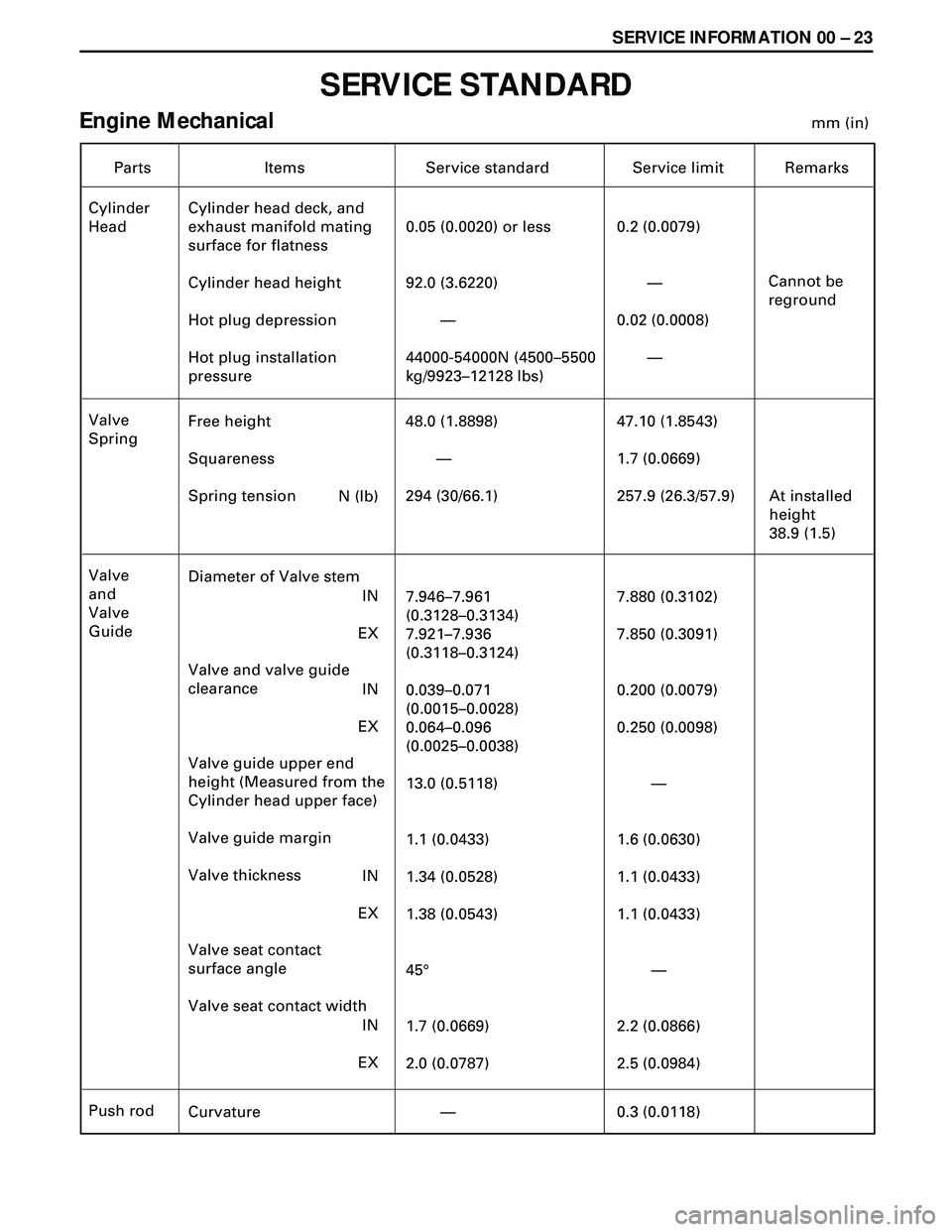
SERVICE STANDARD
Engine Mechanicalmm (in)
Parts Items Service standard
Cylinder
HeadCylinder head deck, and
exhaust manifold mating
surface for flatness
Cylinder head height
Hot plug depression
Hot plug installation
pressure0.05 (0.0020) or less
92.0 (3.6220)
—
44000-54000N (4500–5500
kg/9923–12128 lbs)
0.2 (0.0079)
—
0.02 (0.0008)
—Service limit Remarks
Cannot be
reground
Free height
Squareness
Spring tension 48.0 (1.8898)
—
294 (30/66.1) Valve
Spring47.10 (1.8543)
1.7 (0.0669)
257.9 (26.3/57.9) At installed
height
38.9 (1.5) N (lb)
Diameter of Valve stem
Valve and valve guide
clearance
Valve guide upper end
height (Measured from the
Cylinder head upper face)
Valve guide margin
Valve thickness
Valve seat contact
surface angle
Valve seat contact width7.946–7.961
(0.3128–0.3134)
7.921–7.936
(0.3118–0.3124)
0.039–0.071
(0.0015–0.0028)
0.064–0.096
(0.0025–0.0038)
13.0 (0.5118)
1.1 (0.0433)
1.34 (0.0528)
1.38 (0.0543)
45¡
1.7 (0.0669)
2.0 (0.0787) Valve
and
Valve
Guide7.880 (0.3102)
7.850 (0.3091)
0.200 (0.0079)
0.250 (0.0098)
—
1.6 (0.0630)
1.1 (0.0433)
1.1 (0.0433)
—
2.2 (0.0866)
2.5 (0.0984) IN
EX
IN
EX
IN
EX
IN
EX
Curvature — Push rod
0.3 (0.0118)
Page 1535 of 3573
SERVICE INFORMATION 00 Ð 35
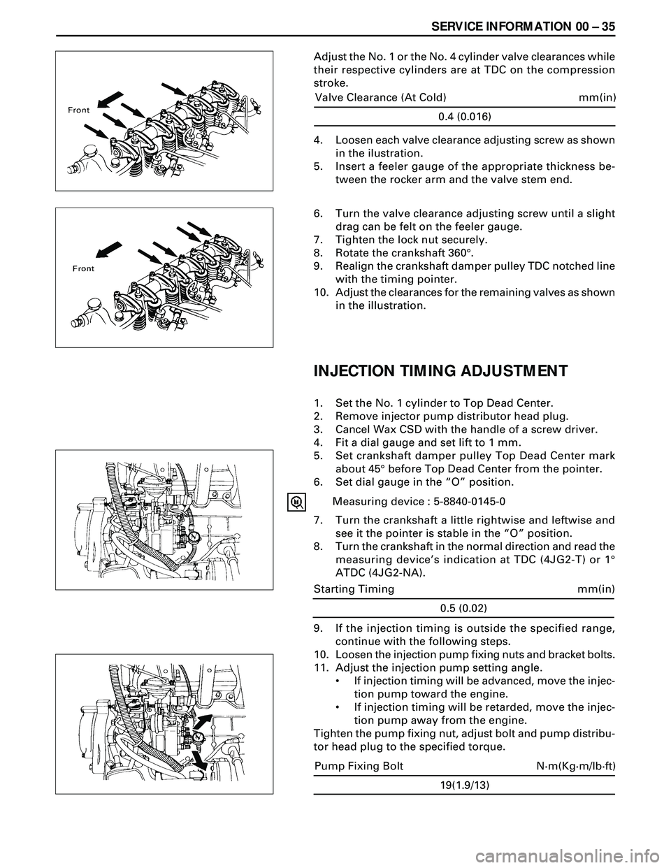
Adjust the No. 1 or the No. 4 cylinder valve clearances while
their respective cylinders are at TDC on the compression
stroke.
0.4 (0.016)
mm(in) Valve Clearance (At Cold)
4. Loosen each valve clearance adjusting screw as shown
in the ilustration.
5. Insert a feeler gauge of the appropriate thickness be-
tween the rocker arm and the valve stem end.
6. Turn the valve clearance adjusting screw until a slight
drag can be felt on the feeler gauge.
7. Tighten the lock nut securely.
8. Rotate the crankshaft 360°.
9. Realign the crankshaft damper pulley TDC notched line
with the timing pointer.
10. Adjust the clearances for the remaining valves as shown
in the illustration.
INJECTION TIMING ADJUSTMENT
1. Set the No. 1 cylinder to Top Dead Center.
2. Remove injector pump distributor head plug.
3. Cancel Wax CSD with the handle of a screw driver.
4. Fit a dial gauge and set lift to 1 mm.
5. Set crankshaft damper pulley Top Dead Center mark
about 45° before Top Dead Center from the pointer.
6. Set dial gauge in the ÒOÓ position.
Measuring device : 5-8840-0145-0
7. Turn the crankshaft a little rightwise and leftwise and
see it the pointer is stable in the ÒOÓ position.
8. Turn the crankshaft in the normal direction and read the
measuring deviceÕs indication at TDC (4JG2-T) or 1°
ATDC (4JG2-NA).
9. If the injection timing is outside the specified range,
continue with the following steps.
10. Loosen the injection pump fixing nuts and bracket bolts.
11. Adjust the injection pump setting angle.
¥ If injection timing will be advanced, move the injec-
tion pump toward the engine.
¥ If injection timing will be retarded, move the injec-
tion pump away from the engine.
Tighten the pump fixing nut, adjust bolt and pump distribu-
tor head plug to the specified torque.
19(1.9/13)
N·m(Kg·m/lb·ft) Pump Fixing Bolt
0.5 (0.02)
mm(in) Starting Timing
Page 1536 of 3573
00 Ð 36 SERVICE INFORMATION
CAUTION
¥ When installing the distributor head plug, be sure to use
new copper washer.
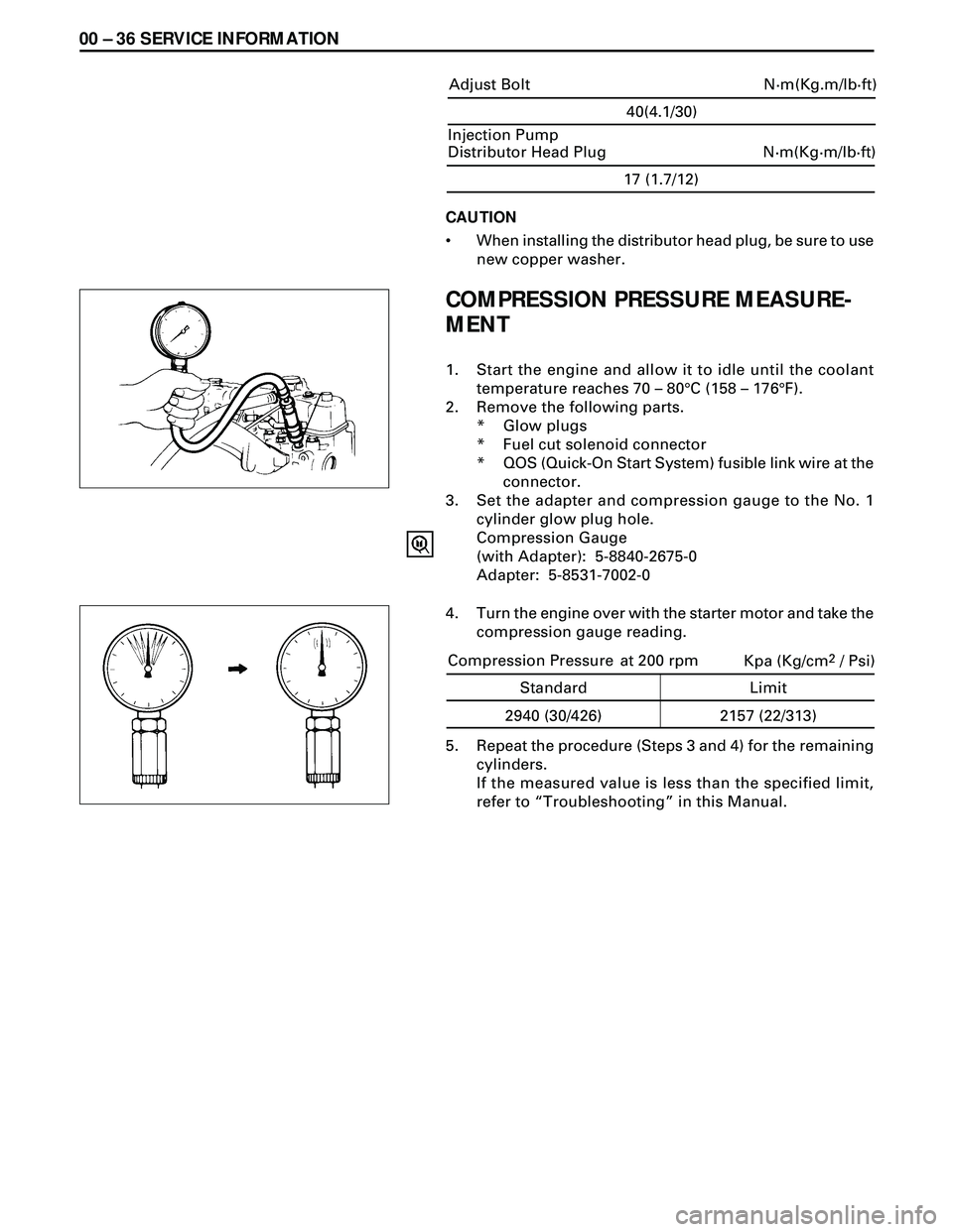
COMPRESSION PRESSURE MEASURE-
MENT
1. Start the engine and allow it to idle until the coolant
temperature reaches 70 Ð 80°C (158 Ð 176°F).
2. Remove the following parts.
* Glow plugs
* Fuel cut solenoid connector
* QOS (Quick-On Start System) fusible link wire at the
connector.
3. Set the adapter and compression gauge to the No. 1
cylinder glow plug hole.
Compression Gauge
(with Adapter): 5-8840-2675-0
Adapter: 5-8531-7002-0
5. Repeat the procedure (Steps 3 and 4) for the remaining
cylinders.
If the measured value is less than the specified limit,
refer to ÒTroubleshootingÓ in this Manual.
17 (1.7/12)
N·m(Kg·m/lb·ft) Injection Pump
Distributor Head Plug
4. Turn the engine over with the starter motor and take the
compression gauge reading.
40(4.1/30)
N·m(Kg.m/lb·ft) Adjust Bolt
Kpa (Kg/cm2 / Psi)
Standard Limit
2940 (30/426) 2157 (22/313) Compression Pressure at 200 rpm
Page 1538 of 3573
00 Ð 38 SERVICE INFORMATION
FIXING TORQUE
CYLINDER HEAD COVER, CYLINDER HEAD ROCKER,
SHAFT BRAKER
Nám (Kgám/lbáft)
Page 1551 of 3573
ENGINE MECHANICAL 6A Ð 1
SECTION 6A
ENGINE MECHANICAL
CONTENTS
PAGE
Cylinder Head ..................................................................................................................6A- 2
Valve Springs, Valve Stem Oil Seal, Valve, Valve Guide, Push rod ........................... 6A- 7
Camshaft, Tappet ............................................................................................................ 6A-14
Rocker Arm Assembly .................................................................................................... 6A-19
Oil pump .......................................................................................................................... 6A-21
Crankshaft ........................................................................................................................ 6A-25
Piston and Connecting Rod ............................................................................................ 6A-34
Cylinder Block .................................................................................................................. 6A-42
Page 1552 of 3573
6A Ð 2 ENGINE MECHANICAL
CYLINDER HEAD
NOTE:
·During disassembly, be sure that the valve train
components are kept together and identified so that
they can be re-installed in their original locations.
·Before removing the cylinder head from the engine
and before disassembling the valve mechanism, make
a compression test and note the results.
DISASSEMBLY
1. Thermostat Housing Assembly
2. Injection Nozzle Holder
3. Glow Plug and Glow Plug Connector
4. Rocker Arm Shaft and Rocker Arm
5. Push Rod
6. Cylinder Head
·Refer to Section 6A2 ÒCylinder HeadÓ
CLEAN
·Cylinder head bolts
·Cylinder head
Carefully remove all varnish, soot and carbon to the
bare metal. Do not use a motorized wire brush on any
gasket sealing surface.
Page 1553 of 3573
ENGINE MECHANICAL 6A Ð 3
INSPECTION AND REPAIR
Make the necessary adjustments, repairs, and part re-
placements if excessive wear or damage is discovered
during inspection.
·Cylinder head gasket and mating surfaces for leaks,
corrosion and blow-by. If the gasket has failed,
determine the cause;
Ð Improper installation
Loose or warped cylinder head
Ð Insufficient torque on head bolts
Ð Warped case surface
1. Cylinder head bolts for damaged threads or stretch-
ing and damaged heads caused by improper use of
tools.
CAUTION:
Suspected bolts must be replaced.
2. Cylinder head for cracks, especially between valve
seats and in the exhaust ports.
3. Cylinder head deck for corrosion, sand particles in
head and porosity.
CAUTION:
Do not attempt to weld the cylinder head. Replace it.
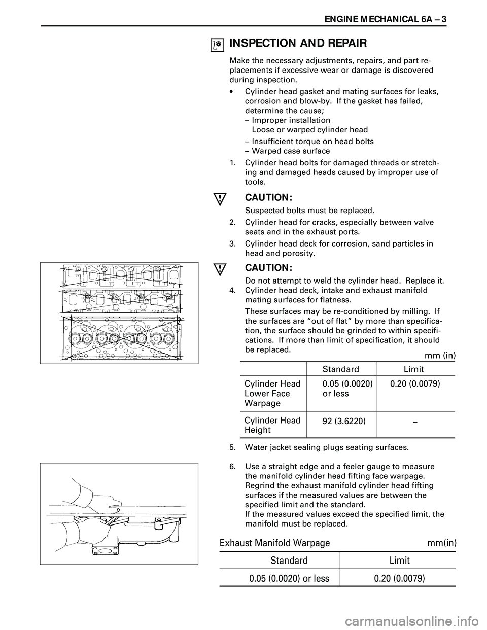
4. Cylinder head deck, intake and exhaust manifold
mating surfaces for flatness.
These surfaces may be re-conditioned by milling. If
the surfaces are Òout of flatÓ by more than specifica-
tion, the surface should be grinded to within specifi-
cations. If more than limit of specification, it should
be replaced.
5. Water jacket sealing plugs seating surfaces.
6. Use a straight edge and a feeler gauge to measure
the manifold cylinder head fifting face warpage.
Regrind the exhaust manifold cylinder head fifting
surfaces if the measured values are between the
specified limit and the standard.
If the measured values exceed the specified limit, the
manifold must be replaced.
Cylinder Head
Lower Face
Warpagemm (in)
0.05 (0.0020)
or less0.20 (0.0079)
Cylinder Head
Height92 (3.6220)
–
Standard Limit
Standard Limit
mm(in)
0.05 (0.0020) or less 0.20 (0.0079) Exhaust Manifold Warpage