Page 1041 of 3573
6A±85
ENGINE MECHANICAL
Cylinder Block
Cylinder Block and Associated Parts
012RW010
Legend
(1) Cylinder Head Assembly
(2) Cylinder Head Gasket
(3) Crankcase with Oil Pan
(4) Oil Pipe and O-Ring
(5) Oil Strainer and O-Ring
(6) Oil Pump Assembly
(7) Cylinder Block Side Bolts(8) Oil Gallery
(9) Piston and Connecting Rod Assembly
(10) Flywheel
(11) Rear Oil Seal Retainer Assembly
(12) Main Bearing Cap
(13) Crankshaft
(14) Cylinder Block
Disassembly
1. Remove cylinder head assembly.
2. Remove cylinder head gasket.
3. Remove crankcase with oil pan.
4. Remove oil pipe and O-ring.5. Remove oil strainer and O-ring.
6. Remove oil pump assembly.
7. Remove crankcase side bolts.
8. Remove oil gallery.
9. Remove piston and connecting rod assembly.
10. Remove flywheel.
Page 1042 of 3573

6A±86
ENGINE MECHANICAL
11. Remove rear oil seal retainer assembly.
12. Remove main bearing cap.
13. Remove crankshaft.
14. Remove cylinder block.
Inspection and Repair
1. Remove the cylinder head gasket and any other
material adhering to the upper surface of the cylinder
block. Be very careful not to allow any material to
accidentally drop into the cylinder block. Be very
careful not to scratch the cylinder block.
2. Carefully remove the oil pump, rear oil seal retainer,
and crankcase assembly installation surface seal.
3. Wipe the cylinder block clean.
4. Visually inspect the cylinder block. If necessary, use a
flaw detector to perform a dye penetrate and
hydraulic (or air pressure) test. If cracking or other
damage is discovered, the cylinder block must either
be repaired or replaced.
Flatness
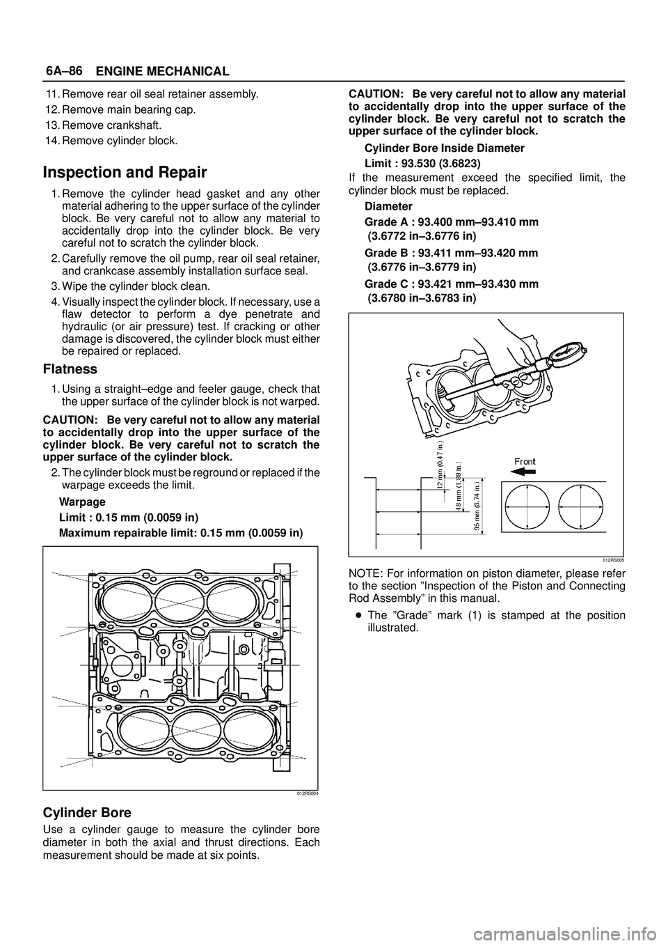
1. Using a straight±edge and feeler gauge, check that
the upper surface of the cylinder block is not warped.
CAUTION: Be very careful not to allow any material
to accidentally drop into the upper surface of the
cylinder block. Be very careful not to scratch the
upper surface of the cylinder block.
2. The cylinder block must be reground or replaced if the
warpage exceeds the limit.
Warpage
Limit : 0.15 mm (0.0059 in)
Maximum repairable limit: 0.15 mm (0.0059 in)
012RS004
Cylinder Bore
Use a cylinder gauge to measure the cylinder bore
diameter in both the axial and thrust directions. Each
measurement should be made at six points.CAUTION: Be very careful not to allow any material
to accidentally drop into the upper surface of the
cylinder block. Be very careful not to scratch the
upper surface of the cylinder block.
Cylinder Bore Inside Diameter
Limit : 93.530 (3.6823)
If the measurement exceed the specified limit, the
cylinder block must be replaced.
Diameter
Grade A : 93.400 mm±93.410 mm
(3.6772 in±3.6776 in)
Grade B : 93.411 mm±93.420 mm
(3.6776 in±3.6779 in)
Grade C : 93.421 mm±93.430 mm
(3.6780 in±3.6783 in)
012RS005
NOTE: For information on piston diameter, please refer
to the section ºInspection of the Piston and Connecting
Rod Assemblyº in this manual.
�The ºGradeº mark (1) is stamped at the position
illustrated.
Page 1045 of 3573

6A±89
ENGINE MECHANICAL
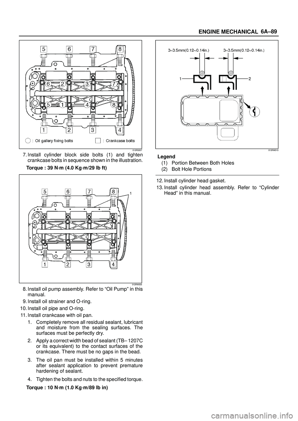
012RS007
7. Install cylinder block side bolts (1) and tighten
crankcase bolts in sequence shown in the illustration.
Torque : 39 N´m (4.0 Kg´m/29 lb ft)
012RW005
8. Install oil pump assembly. Refer to ªOil Pumpº in this
manual.
9. Install oil strainer and O-ring.
10. Install oil pipe and O-ring.
11. Install crankcase with oil pan.
1. Completely remove all residual sealant, lubricant
and moisture from the sealing surfaces. The
surfaces must be perfectly dry.
2. Apply a correct width bead of sealant (TB± 1207C
or its equivalent) to the contact surfaces of the
crankcase. There must be no gaps in the bead.
3. The oil pan must be installed within 5 minutes
after sealant application to prevent premature
hardening of sealant.
4. Tighten the bolts and nuts to the specified torque.
Torque : 10 N´m (1.0 Kg´m/89 lb in)
013RW010
Legend
(1) Portion Between Both Holes
(2) Bolt Hole Portions
12. Install cylinder head gasket.
13. Install cylinder head assembly. Refer to ªCylinder
Headº in this manual.
Page 1048 of 3573
6A±92
ENGINE MECHANICAL
Cylinder head cover, Cylinder head, Camshaft bracket, Common chamber, EGR valve and EGR pipe
N´m (Kg´m/Ib ft)
E06RW043
Page 1052 of 3573
6A±96
ENGINE MECHANICAL
Special Tool
ILLUSTRATIONTOOL NO.
TOOL NAME
5±8840±0011±0
(J±21687±02)
Remover; tie rod end
5±8840±2441±0
Set Number of Valve
Compressor
5±8840±2446±0
(J±8062)
Compressor; Valve
Spring (1)
5±8840±2547±0
(J±42898)
Adapter; Compressor
Valve Spring (2)
5±8840±0623±0
(J±37281)
Remover; Oil controller
5±8840±0624±0
(J±38537)
Installer; Oil controller
5±8840±2445±0
(J±42985)
Installer; Camshaft oil
seal
5±8840±2545±0
(J±39206)
Installer; Pilot bearing
ILLUSTRATIONTOOL NO.
TOOL NAME
5±8840±0133±0
(J±8614±01)
Holder; Crankshaft
5±8840±2153±0
(J±37228)
Seal cutter
5±8840±2286±0
(J±39201)
Installer; Real oil seal
9±8511±4209±0
(J±24239±1)
Cylinder head bolt
wrench
5±8840±2442±0
(J±42899)
Replacer; Valve guide
(set) (1,2)
5±8840±2548±0
(J±42687)
Installer; Valve guide (1)
5±8840±2549±0
(J±37985±1)
Remover; Valve guide
(2)
5±8840±2444±0
(J±42689)
Adjusting Tool: Valve
clearance
Page 1055 of 3573
6B±2
ENGINE COOLING
General Description
030RW001
Legend
(1) Water Pump
(2) Thermostat
(3) Radiator
(4) Reserve Tank
(5) Cooling Fan
(6) Cylinder Block(7) Cylinder Head
(8) Right Bank
(9) Throttle Body
(10) Cylinder Block
(11) Cylinder Head
(12) Left Bank
(13) Heater
The cooling system is a pressurized Engine Coolant (EC)
forced circulation type which consists of a water pump,
thermostat cooling fan, radiator and other components.
The automatic transmission fluid is cooled by the EC in
radiator.
Water Pump
The EC pump is a centrifugal impeller type and is driven
by a timing belt.
030RS001
Page 1058 of 3573
ENGINE COOLING6B±5
Diagnosis
Engine Cooling Trouble
ConditionPossible causeCorrection
Engine overheatingLow Engine Coolant levelReplenish
Incorrect fan installedReplace
Thermo meter unit faultyReplace
Faulty thermostatReplace
Faulty Engine Coolant temperature
sensorRepair or replace
Clogged radiatorClean or replace
Faulty radiator capReplace
Low engine oil level or use of
improper engine oilReplenish or change oil
Clogged exhaust systemClean exhaust system or replace
faulty parts
Faulty Throttle Position sensorReplace throttle valve assembly
Open or shorted Throttle Position
sensor circuitRepair or replace
Damaged cylinder head gasketReplace
Engine overcoolingFaulty thermostatReplace
Engine slow to warm±upFaulty thermostatReplace
Thermo unit faultyReplace
Page 1088 of 3573

6D2±3
IGNITION SYSTEM
Ignition Coil
Removal
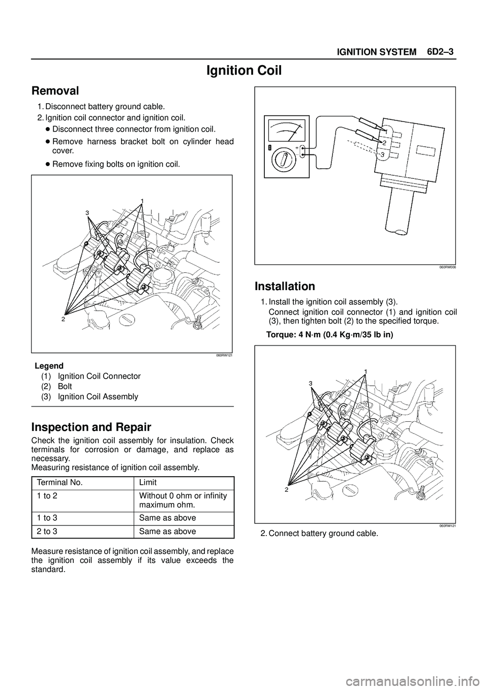
1. Disconnect battery ground cable.
2. Ignition coil connector and ignition coil.
�Disconnect three connector from ignition coil.
�Remove harness bracket bolt on cylinder head
cover.
�Remove fixing bolts on ignition coil.
060RW121
Legend
(1) Ignition Coil Connector
(2) Bolt
(3) Ignition Coil Assembly
Inspection and Repair
Check the ignition coil assembly for insulation. Check
terminals for corrosion or damage, and replace as
necessary.
Measuring resistance of ignition coil assembly.
Terminal No.
Limit
1 to 2Without 0 ohm or infinity
maximum ohm.
1 to 3Same as above
2 to 3Same as above
Measure resistance of ignition coil assembly, and replace
the ignition coil assembly if its value exceeds the
standard.
060RW006
Installation
1. Install the ignition coil assembly (3).
Connect ignition coil connector (1) and ignition coil
(3), then tighten bolt (2) to the specified torque.
Torque: 4 N´m (0.4 Kg´m/35 lb in)
060RW121
2. Connect battery ground cable.