Page 1626 of 3573
6A2 Ð 24 4JG2-NA/4JG2-TURBO ENGINE
ROCKER ARM SHAFT ASSEMBLY
REMOVAL
Preparation
·Disconnect battery ground cable.
1. Air Cleaner Cover & Air Duct (4JG2-T Only)
·Disconnect air hoses.
·Release clips and bands and remove air cleaner
cover.
2. Intercooler Assembly (4JG2-T Only)
·Refer to intercooler removal steps in this section.
3. Oil Level Gauge Tube
4. Cylinder Head Cover
5. Rocker Arm Shaft Assembly
·Loosen bolts and nuts of rocker arm shaft bracket
by turns and remove rocker shaft asm.
Page 1627 of 3573
4JG2-NA/4JG2-TURBO ENGINE 6A2 Ð 25
INSTALLATION
5. Rocker Arm Shaft Assembly
·Install rocker arm shaft with larger oil hole (¿4) to
the front of engine.
·Align fixing bolt with not of rocker arm shaft and
tighten fixing bolts to the specified torque.
54 (5.5/40)N·m (kg·m/lb·ft)
·Adjust valve clearance refreshing to section valve
clearance adjustment.
4. Cylinder Head Cover
·Install cylinder head cover and tighten bolts to the
specified torque.
3. Oil Level Gauge Guide Tube
·Tighten guide tube to the specified torque.
2. Intercooler Assembly (4JG2-T Only)
·Refer to intercooler installation steps in this
section.
1. Air Cleaner Cover & Air Duct (4JG2-T Only)
13 (1.3/113)N·m (kg·m/lb·in)
19 (1.9/14)N·m (kg·m/lb·ft)
Page 1628 of 3573
6A2 Ð 26 4JG2-NA/4JG2-TURBO ENGINE
CYLINDER HEAD
Page 1630 of 3573

6A2 Ð 28 4JG2-NA/4JG2-TURBO ENGINE
16. Exh. Manifold; W/turbo (4JG2-T Only)
·Remove exh. manifold bracket fixing bolt from
exh. manifold.
·Remove exh. manifold fixing bolts and nuts from
cylinder head.
·After pulling out exh. manifold a little, remove oil
return pipe flange from stud bolt and remove exh.
manifold w/turbo.
17. Front Exhaust Pipe
18. Fuel Leak Off Hose
19. Cylinder Head Cover
20. Glow Plug Harness
21. Injection Pipe
·Loosen sleeve nuts on injection pump side.
·Disconnect sleeve nuts on injection pipe.
22. Fuel Leak Off Pipe
23. Rocker Arm Shaft Assembly
24. Push Rod
25. Cylinder Head W/inlet Manifold
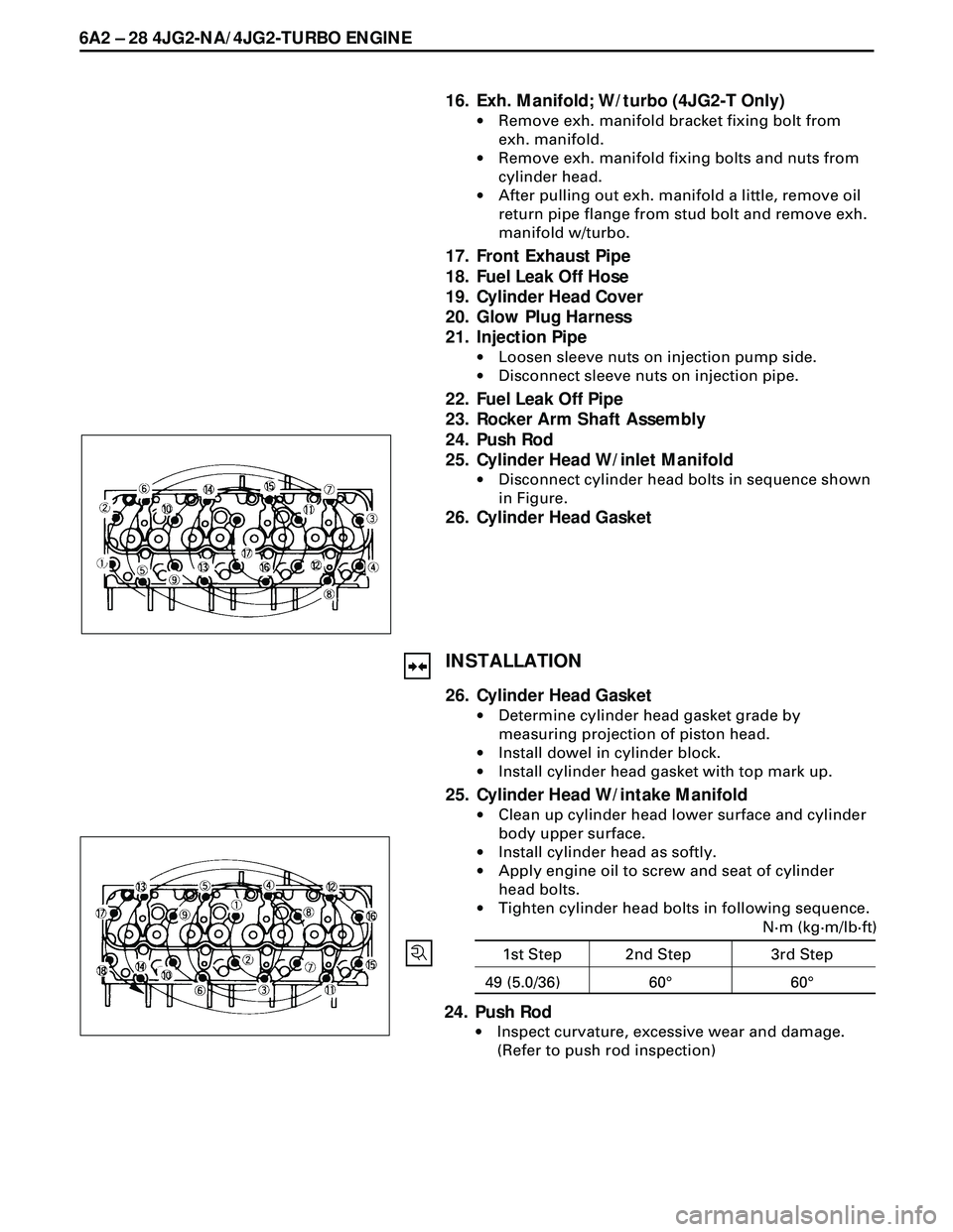
·Disconnect cylinder head bolts in sequence shown
in Figure.
26. Cylinder Head Gasket
INSTALLATION
26. Cylinder Head Gasket
·Determine cylinder head gasket grade by
measuring projection of piston head.
·Install dowel in cylinder block.
·Install cylinder head gasket with top mark up.
25. Cylinder Head W/intake Manifold
·Clean up cylinder head lower surface and cylinder
body upper surface.
·Install cylinder head as softly.
·Apply engine oil to screw and seat of cylinder
head bolts.
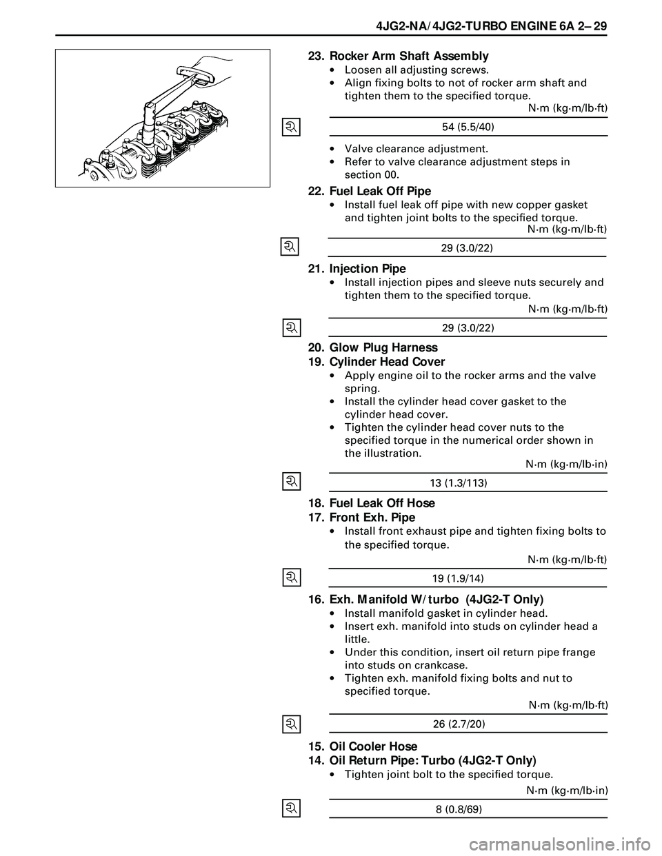
·Tighten cylinder head bolts in following sequence.
24. Push Rod
·Inspect curvature, excessive wear and damage.
(Refer to push rod inspection)
1st Step
N·m (kg·m/lb·ft)
49 (5.0/36)
2nd Step
60°3rd Step
60°
Page 1631 of 3573

4JG2-NA/4JG2-TURBO ENGINE 6A 2Ð 29
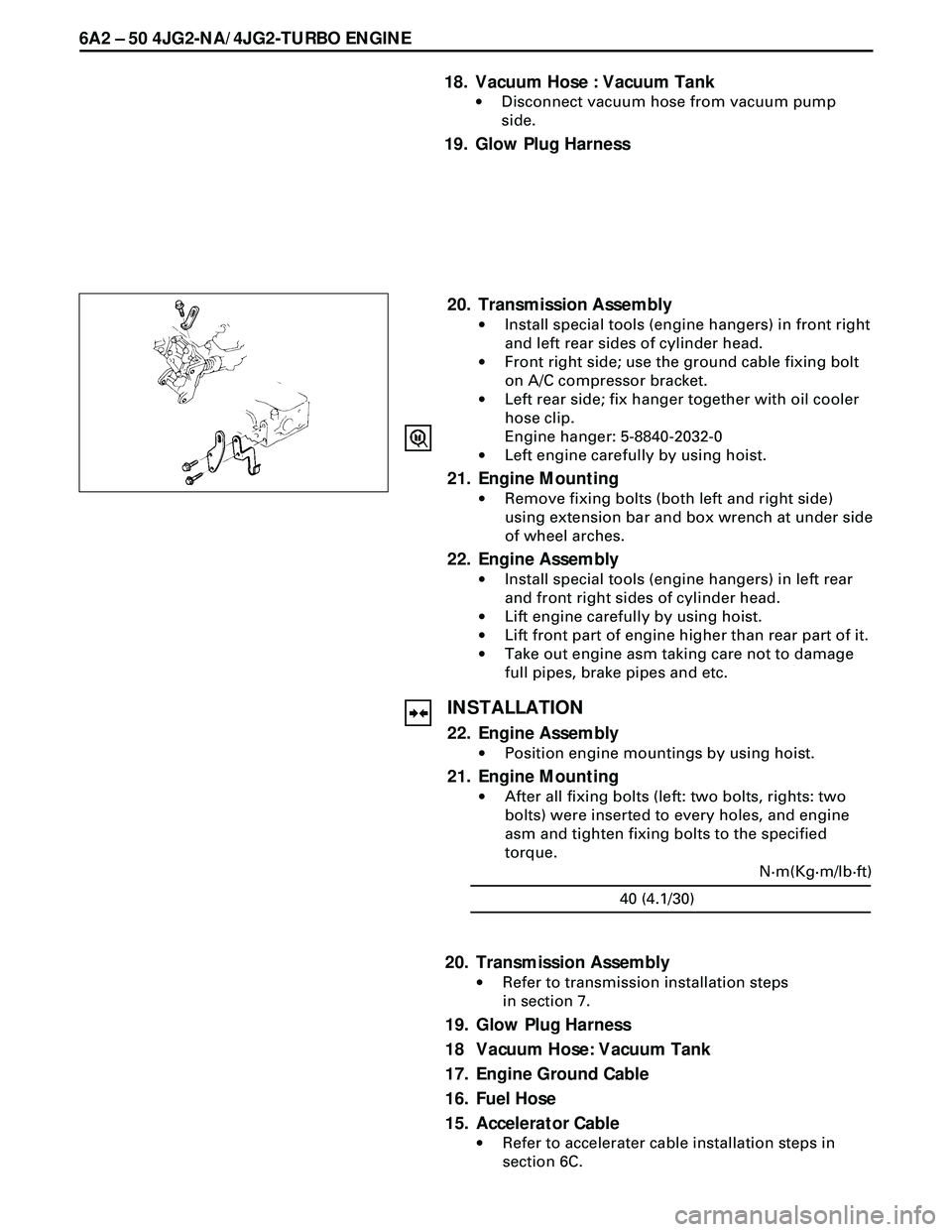
23. Rocker Arm Shaft Assembly
·Loosen all adjusting screws.
·Align fixing bolts to not of rocker arm shaft and
tighten them to the specified torque.
·Valve clearance adjustment.
·Refer to valve clearance adjustment steps in
section 00.
22. Fuel Leak Off Pipe
·Install fuel leak off pipe with new copper gasket
and tighten joint bolts to the specified torque.
54 (5.5/40)N·m (kg·m/lb·ft)
21. Injection Pipe
·Install injection pipes and sleeve nuts securely and
tighten them to the specified torque.
29 (3.0/22)N·m (kg·m/lb·ft)
29 (3.0/22)N·m (kg·m/lb·ft)
20. Glow Plug Harness
19. Cylinder Head Cover
·Apply engine oil to the rocker arms and the valve
spring.
·Install the cylinder head cover gasket to the
cylinder head cover.
·Tighten the cylinder head cover nuts to the
specified torque in the numerical order shown in
the illustration.
18. Fuel Leak Off Hose
17. Front Exh. Pipe
·Install front exhaust pipe and tighten fixing bolts to
the specified torque.
13 (1.3/113)N·m (kg·m/lb·in)
19 (1.9/14)N·m (kg·m/lb·ft)
16. Exh. Manifold W/turbo (4JG2-T Only)
·Install manifold gasket in cylinder head.
·Insert exh. manifold into studs on cylinder head a
little.
·Under this condition, insert oil return pipe frange
into studs on crankcase.
·Tighten exh. manifold fixing bolts and nut to
specified torque.
26 (2.7/20)N·m (kg·m/lb·ft)
15. Oil Cooler Hose
14. Oil Return Pipe: Turbo (4JG2-T Only)
·Tighten joint bolt to the specified torque.
8 (0.8/69)N·m (kg·m/lb·in)
Page 1639 of 3573
4JG2-NA/4JG2-TURBO ENGINE 6A2 Ð 37
PISTON, PISTON RING AND CONNECTING ROD
REMOVAL
1. Cylinder Head
·Refer to ÒCylinder HeadÓ removal in this sec-
tion.
2. Crankcase
·Refer to ÒCrankcaseÓ in this section.
3. Connecting Rod Bearing Cap
·Before removing the bearing cap, remove
carbon on the top of cylinder bore.
4. Piston, Piston Rings and Connecting Rod
·Push piston and connecting rod out from the
top of cylinder bore.
INSTALLATION
4. Piston, Piston Rings and Connecting Rod
·Apply engine oil to cylinder bore, connecting
rod bearings and crank pins.
·In installing the piston, its front mark must face
the engine front side.
3. Connecting Rod Bearing Cap
·The bearing cap number must be same as
connecting rod number.
·Apply engine oil to the thread and sealing
surface of each nuts.
·Tighten nuts to the specified torque.
Page 1640 of 3573
6A2 Ð 38 4JG2-NA/4JG2-TURBO ENGINE
·After tightening the nuts, make sure that the
crankshaft rotates smoothly.
2. Crankcase
·Refer to ÒCrankcaseÓ in this section.
1. Cylinder Head
·Refer to ÒCylinder HeadÓ installation in this sec-
tion.
1st step 29 (3.0/22) 2nd step 45° – 60°N·m(Kg·m/lb·ft)
Page 1652 of 3573

6A2 Ð 50 4JG2-NA/4JG2-TURBO ENGINE
18. Vacuum Hose : Vacuum Tank
·Disconnect vacuum hose from vacuum pump
side.
19. Glow Plug Harness
20. Transmission Assembly
·Install special tools (engine hangers) in front right
and left rear sides of cylinder head.
·Front right side; use the ground cable fixing bolt
on A/C compressor bracket.
·Left rear side; fix hanger together with oil cooler
hose clip.
Engine hanger: 5-8840-2032-0
·Left engine carefully by using hoist.
21. Engine Mounting
·Remove fixing bolts (both left and right side)
using extension bar and box wrench at under side
of wheel arches.
22. Engine Assembly
·Install special tools (engine hangers) in left rear
and front right sides of cylinder head.
·Lift engine carefully by using hoist.
·Lift front part of engine higher than rear part of it.
·Take out engine asm taking care not to damage
full pipes, brake pipes and etc.
INSTALLATION
22. Engine Assembly
·Position engine mountings by using hoist.
21. Engine Mounting
·After all fixing bolts (left: two bolts, rights: two
bolts) were inserted to every holes, and engine
asm and tighten fixing bolts to the specified
torque.
40 (4.1/30)N·m(Kg·m/lb·ft)
20. Transmission Assembly
·Refer to transmission installation steps
in section 7.
19. Glow Plug Harness
18 Vacuum Hose: Vacuum Tank
17. Engine Ground Cable
16. Fuel Hose
15. Accelerator Cable
·Refer to accelerater cable installation steps in
section 6C.