Page 1678 of 3573

6C Ð 12 FUEL SYSTEM
·Install retaining nut and tighten nut to the specified
torque.
ADJUSTMENT OF INJECTION STARTING PRES-
SURE
·Set nozzle holder asm on a nozzle tester.
·Apply hydraulic pressure by operating tester
handle, and make sure fuel cam be injected under
the following pressure.
CAUTION
·In case of DFI test results are O.K. if the sub-hole
inject fuel in spray.
14710 (150/2133)Kpa (Kg/cm
2/Psi)
CAUTION
·If not injected under the specified pressure, adjust
with adjusting shim.
Ref. Types are available in the 1.0 Ð 1.75 mm (0.039 Ð
0.069 in) thickness range (on a 0.01 mm (0.0004 in)
basis).
·Unless extremely deformed spray in seen, there is
no problem.
INSTALLATION
DFI should be positioned correctly and then installed in
the cylinder head, because the sub-hole must be set in the
specified direction.
CAUTION
·Nozzle and assembling should be as illustrated.
·Use new heat shield and new corrugated washer.
5. Injection Nozzle
·Lightly tighten the holder nut to suck extent that the
nozzle holder can turn one word and one word.
·Set positioning confirmation drilled hole (¿2) within
a nozzle turning angle of ± 5¡ against the cylinder
head-side positioning boss.
39 (4/35)N·m (Kg·m/lb·ff)
Page 1679 of 3573
FUEL SYSTEM 6C Ð 13
·Apply a wrench as illustrated, and tighten the
holder nut to the specified torque using a special
tool.
wrench: nozzle holder 5-8840-0259-0
CAUTION
·After tightening the holder nut, make sure that the
drilled hole makes ± 5¡ or smaller with the cylinder
head-side positioning boss.
·When mounting leak off pipe, injection nozzle and
pipe, clean then with air so that dust may not enter.
4. Leak Off Pipe
·Mount using a new copper waker
3. Injection Pipe
·Connect injection pipe to nozzle holder.
·Tighten the injection pump side.
·Fit pipe clip in specified position.
2. Air Cleaner Cover & Air duct
1. Intercooler Assembly
·Refer to ÒIntercoolerÓ installation in section 6A2.
64 (6.5/47)N·m (Kg·m/lb.ft)
Page 1683 of 3573

FUEL SYSTEM 6C Ð 17
·If it reads abnormal, loosen injection pump fixing nut
and pump bracket adjust bolt, make adjustment by
changing the pump mounting angle, and tighten
the nut and bolt to the specified torque where the
dial indicates the specified valve.
Pump fixing nut
Adjust bolt
·Remove the measuring device and tighten the
distributor head plug to the specified torque.
CAUTION
·When installing the distributor head plug, be sure to
use new copper washer.
·Connect injection pipe.
·Fit pipe clip where specified.
INJECTION TIMING ADJUSTMENT
·Set No.1 cylinder to top dead center.
·Remove injection pump distributor head plug.
·Cancel wax CSD with the handle of a driver.
·Fit a dial gauge and set lift to 2 mm(0.0787 in).
Measuring device: 5-8840-0145-0
·Set crankshaft damper pully top dead center mark
about 45¡ before top dead center from the pointer.
·Set dial gauge in the Ò0Ó position.
·Turn the crankshaft a little rightwise and leftwise
and see if the pointer is stable in the Ò0Ó position.
·Turn the crankshaft in the normal direction and
read the measuring diviceÕs indication at TDC
(4JG2-T) and ATDC 1¡ (4JG2-NA)
0.5 (0.0197)mm(in)Standard
19 (1.9/13)
N·m (Kg·m/lb·ft)
40 (4.1/30)
N·m (Kg·m/lb·ft)
17 (1.7/12)N·m (Kg·m/lb·ft)
Page 1734 of 3573

ENGINE MECHANICAL 6A – 1
ENGINE
ENGINE MECHANICAL
CONTENTS
General Description . . . . . . . . . . . . . . . . . . . . 6A–2
Service Information . . . . . . . . . . . . . . . . . . . . 6A–3
Service Standard . . . . . . . . . . . . . . . . . . . . . . 6A–6
Servicing . . . . . . . . . . . . . . . . . . . . . . . . . . . . 6A–9
Tightening Torque . . . . . . . . . . . . . . . . . . . . . 6A–14
Special Tools . . . . . . . . . . . . . . . . . . . . . . . . . 6A–25
Engine Assembly . . . . . . . . . . . . . . . . . . . . . . 6A–28
Engine Mount (RH) . . . . . . . . . . . . . . . . . . . . 6A–30
Engine Mount (LH). . . . . . . . . . . . . . . . . . . . . 6A–31
Intercooler . . . . . . . . . . . . . . . . . . . . . . . . . . . 6A–32
Cylinder Head Cover . . . . . . . . . . . . . . . . . . . 6A–33
Intake Manifold . . . . . . . . . . . . . . . . . . . . . . . 6A–35
Exhaust Manifold . . . . . . . . . . . . . . . . . . . . . . 6A–36
Turbocharger . . . . . . . . . . . . . . . . . . . . . . . . . 6A–38Cylinder Head . . . . . . . . . . . . . . . . . . . . . . . . 6A–41
Cylinder Head Gasket . . . . . . . . . . . . . . . . . . 6A–43
Camshaft . . . . . . . . . . . . . . . . . . . . . . . . . . . . 6A–47
Timing Gear . . . . . . . . . . . . . . . . . . . . . . . . . . 6A–52
Valve Stem Seal, Valve Spring and Adjuster . . 6A–60
Valve Clearance Adjustment. . . . . . . . . . . . . . 6A–67
Oil Rail and Injector . . . . . . . . . . . . . . . . . . . . 6A–69
Crank Case . . . . . . . . . . . . . . . . . . . . . . . . . . 6A–72
Crankshaft . . . . . . . . . . . . . . . . . . . . . . . . . . . 6A–74
Piston and Connecting Rod . . . . . . . . . . . . . . 6A–84
Cylinder Block . . . . . . . . . . . . . . . . . . . . . . . . 6A–92
Oil Pump Assembly . . . . . . . . . . . . . . . . . . . . 6A–98
Oil Filter Cartridge . . . . . . . . . . . . . . . . . . . . . 6A–99
Oil Cooler . . . . . . . . . . . . . . . . . . . . . . . . . . . 6A–99
Page 1735 of 3573

6A – 2 ENGINE MECHANICAL
GENERAL DESCRIPTION
Cylinder Head Gasket
The cylinder head gasket is laminated steel sheets.
Three grades of the gasket according to the measured
piston head projection from the cylinder block are
provided to give the engine a minimum compression
ratio fluctuation.
Tightening Method for
Special Bolt
The cylinder head fixing bolts, flywheel bolts and
connecting rod cap fixing bolts are tightened by the
angular Tightening Method.
Piston
Auto-thermatic pistons having steel struts with a 0.4
mm offset from the piston pin center line, are applied to
reduce thermal expansion and resulting engine noise
when the engine is cold.
Bearings
The crankshaft bearings and connecting rod bearings
are of aluminum having a high bearing surface.
These bearings are especially sensitive to foreign
material such as metal scraps. So, it is very important
that the oil ports and other related surfaces are kept
clean and free of foreign material.
Crankshaft bearings are selected for optimum bearing
and journal clearance which reduces vebration and
noise.
For General Export
For Europe
F06R200004
Page 1739 of 3573

Parts Items Service standard Service limit Remarks
Cylinder Head
Valve Spring
Valve and
Valve guide
Camshaft0.075 (0.0030) or less
95.0 (3.740")
6A – 6 ENGINE MECHANICAL
SERVICE STANDARD
Enginemm (in)
Parts Items Service standard Service limit Remarks
Cylinder Head
Valve Spring
Valve and
Valve guide
Camshaft0.075 (0.0030) or less
95.0 (3.740)
45.7 (1.8)
—
241 (54.2)
6.959 – 6.977
(0.27 –0.272)
6.692 –6.970
(0.271 –0.272)
0.023 –0.056
(0.0009 – 0.0022)
0.03 – 0.063
(0.0011 – 0.0024)
8.0 (0.312)
1.1 (0.0433)
1.2 (0.0472)
1.2 (0.0472)
45°
2.1 (0.0827)
2.1 (0.0827)
0.08 (0.00314)
46.67 (1.8374)
46.77 (1.8413)
29.939 – 29.960
(1.167 – 1.168)
0.02 (0.0008) or less
0.40 – 0.082
(0.0016 – 0.0032)0.50 (0.0197)
—
44.8 (1.765)
1.6 (0.063)
210 (47.22)
6.92 (0.270)
6.90 (0.269)
0.19 (0.0074)
0.20 (0.0079)
—
1.6 (0.0630)
1.1 (0.0433)
1.1 (0.0433)
—
2.6 (0.1024)
2.6 (0.1024)
2.0 (0.00797)
46.57 (1.8335)
46.67 (1.8374)
29.84 (1.1748)
0.10 (0.0039)
0.12 (0.0047)Cannot be
reground Cylinder head lower surface for flatness
Cylinder head height
Free height
Squareness
Spring tension (when assembled) N(lb)
Diameter of Valve stem IN
EX
Valve and valve guide clearance IN
EX
Valve guide upper end height
(Measured from the Cylinder head upper
face)
Valve guide margin
Valve thickness IN
EX
Valve seat contact surface angle
Valve seat contact width IN
EX
End play
Cam lobe height IN
EX
Journal diameter
Runout
Camshaft oil clearance
Page 1748 of 3573
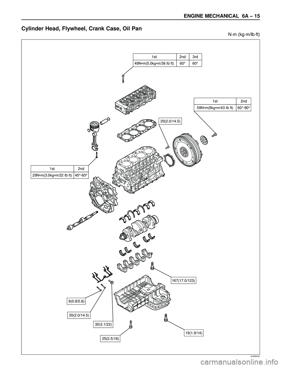
ENGINE MECHANICAL 6A – 15
Cylinder Head, Flywheel, Crank Case, Oil Pan
N·m (kg·m/lb·ft)
012RW121
�
Page 1766 of 3573

ENGINE MECHANICAL 6A – 33
CYLINDER HEAD COVER
REMOVAL
1. Disconnect battery ground cable.
2. Remove clip, remove air cleaner cover and air duct.
3. Remove intercooler assembly.
Refer to “Intercooler” in this manual.
4. Remove PCV hose.
5. Remove bolts which fix noise insulator cover then
remove noise insulator cover and insulator.
6. Remove high pressure oil pipe at cylinder head
side.
Take care when removing the injector oil pipe,
because sometimes, during removal, your hand
can be injured by the remaining high pressure oil.
INSTALLATION
1. Cylinder head cover.
1) Install the cylinder head cover gasket to cylinder
head cover.
2) The gasket must be set perfectly with no loose
areas.
3) Apply liquid gasket (TB1207B or equivalent) to
the rubber seal of the camshaft end, injector
harness gasket area and No. 1 camshaft
bracket.4) Tighten cylinder head cover fixing bolts to the
specified torque.
Torque : 9 N·m (0.9 kg·m/6.5 lb ft)
2. Fill with about 300 cc of engine oil from the high
pressure oil pipe installation port of the oil rail using
an oil rail filler. If assembled without filling the oil rail
with oil, the time for starting the engine will be
longer.
3. Install the high pressure oil pipe immediately and
tighten the sleeve nut to the specified torque.
Torque : 80 N·m (8.1 kg·m/57.9 lb ft)
1 7
2
3
4
5 6
010R200006
Legend
(1) Noise Insulator Cover
(2) Insulator
(3) Bolt(4) Oil Seal
(5) Gasket
(6) Cylinder Head Cover
(7) Bolt
3~52~32~33~5
3~5 1~2
012RW119