Page 1216 of 1681
)
Engine Oil Pressure
Indicator System
Description
NOTE: Refer to page 23-152 for the circuit diagram ofthe engine oil pressure indicator flasher. and to page 23
156 for the input test of the flasher circuit.
The low engine oil pressure indicator light works in twoways. lt will flash continuously following a momentaryloss ol oil pressure, or it will go on and stay on wath a
complete loss of oil pressure.
When the engine first starts, before oil pressure rises
above 29.4 kPa (O.3 kgf/cmr, 4.3 psi), current flows
through the low engine oil pressure indicator light andthe oil pressure switch to ground. This tests the circuit.
With the engine running, voltage is applied to the Ilash-er circuit of the integrated control unit. With normal oilpressure, the oil pressure switch is open and the low en-gine oil pressure indicator light does not operate. lf the
oil pressure switch closes momentarily (more than O.5
seconds). but then opens again, terminal "YEL/RED" will
sense ground through the switch- The integrated con-trol unit will then provide and remove ground tor the low
engine oil pressure indicator light through terminal"YEL/RED". The light will flash on and off untilthe igni
tion switch is turned to "OFF".
lf engine oil pressure talls below 29.4 kPa (O.3 kgf/cmr,
4.3 psi) and does not increase, the oil pressure switchwill stay closed. The low engine oil pressure indicator light
will go on and stay on.
NOTE: Refer to page 23-130 for the engine oil pressure
switch test.
I
23-159
Page 1222 of 1681
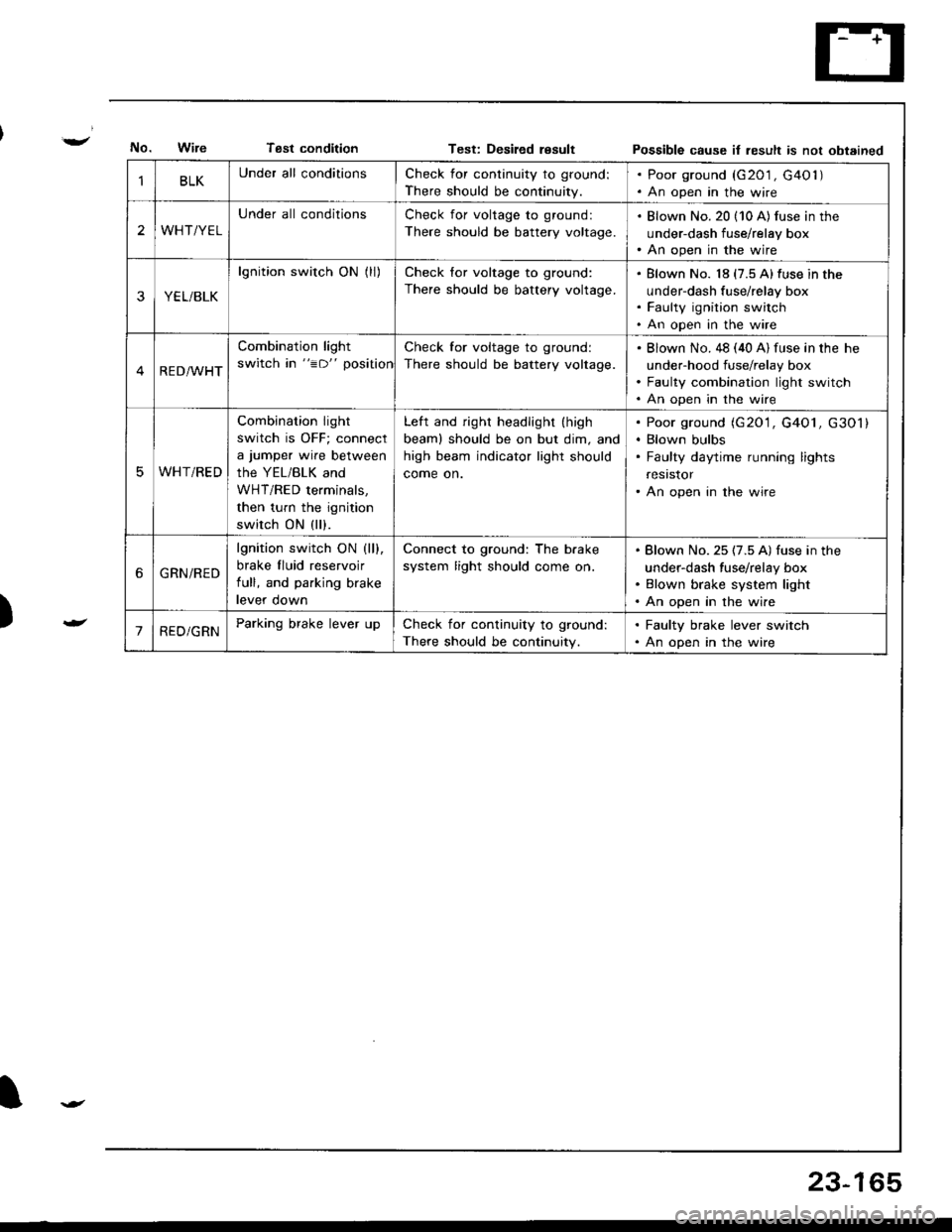
Tsst conditionTest: Desiled resultPossible cause it result is not obtained
)
BLKUnder all conditionsCheck for continuity to ground:
There should be continuity.
. Poor ground (G201 , G40l ). An open in the wire
2WHT/YEL
Under all conditionsCheck for voltage to ground:
There should be battery voltage.
. Blown No. 20 (10 A) fus€ in the
under-dash fuse/relay box. An open in the wire
YEL/BLK
lgnition switch ON (ll)Check for voltage to ground:
There should be battery voltage.
Blown No. 18 (7.5 A)fuse in the
under-dash fuse/relay box
Faulty ignition switch
An open in the wire
RED/WHT
Combination light
switch in "=D" position
Check for voltage to ground:
There should be battery voltage.
Blown No. 48 (40 A) fuse in the he
under-hood fuse/relay box
Faulty combination light switch
An open in the wire
WHT/RED
Combination light
switch is OFF; connect
a jumper wire between
the YEL/BLK and
WHT/RED terminals,
then turn the ignition
switch ON (ll).
Left and right headlight (high
beaml should be on but dim, and
high beam indicator light should
come on.
Poor ground (G20'1, G4O1, G301)
Blown bulbs
Faulty daytime running lights
resrstor
An open in the wire
6GRN/RED
lgnition switch ON (ll).
brake fluid reservoir
full, and parking brake
levef oown
Connect to ground: The b.ake
system light should come on.
Blown No. 25 (7.5 A) fuse in the
under-dash fuse/relay box
Blown brake system light
An open in the wire
'1RED/GRNParking brake lever upCheck for continuity to ground:
There should be continuity.
. Faulty brake lever switch. An open in the wire
23-165
Page 1227 of 1681
Headlight
Adjustment
Befole adiusting the headlights:
a Park the car on level ground.
a Make sure the fuel tank is full.
The driver or someone who weighs the same should
sit in the driver's seat.
Load the trunk with the items you usually carry (if you
usually pull a trailer, attach jt to the car).
Push down on the front and rear bumpers several
times to make sure the car is sitting normally.
When installing a new headlight assembly, tighten the
four mounting bolts so that the indicator in the verti-
cal gauge comes to the "O" mark.
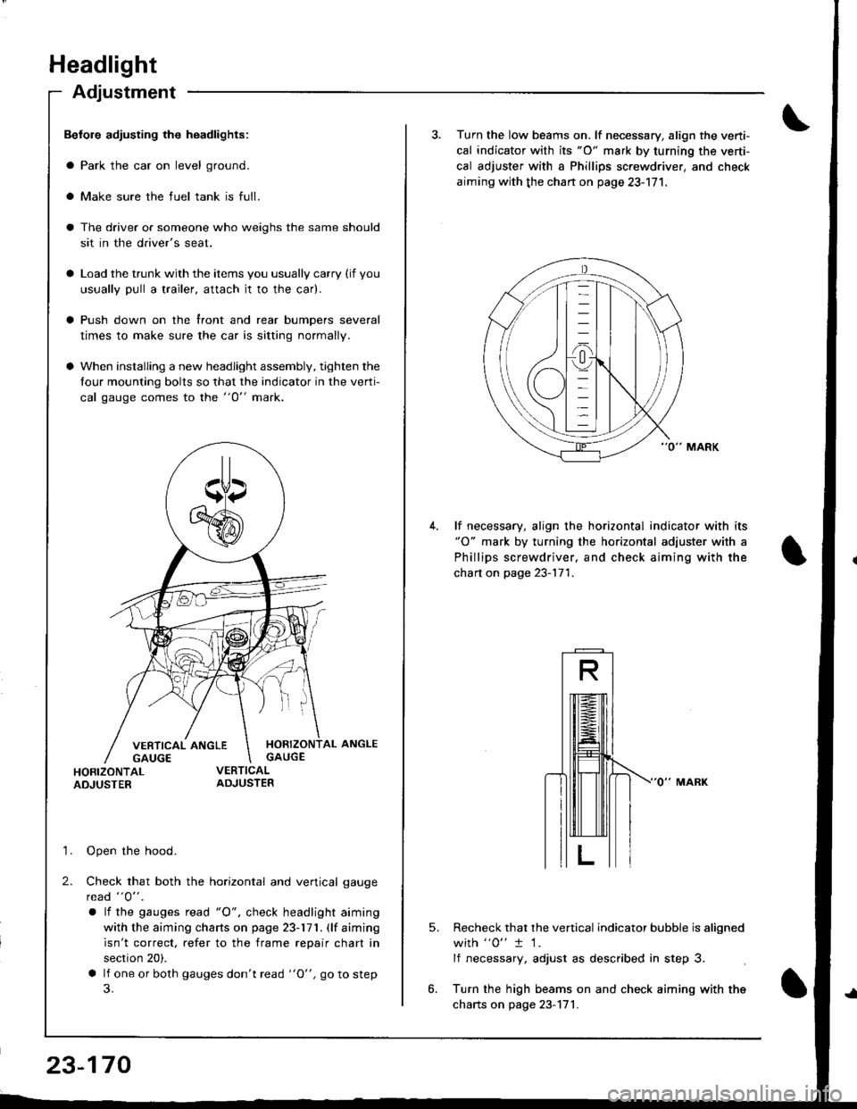
HORIZONTAL ANGLEGAUGE
HORIZONTALADJUSTER
'1. Open the hood.
2. Check that both the horizontal and vertical gauge
rcad "O" .
a lf the gauges tead "O", check headlight aiming
with the aiming charts on page 23-171. (lf aiming
isn't correct. refer to the frame repair chart in
section 20).
a lf one or both gauges don't read "O", go to step
23-170
3. Turn the low beams on. lf necessary, align the verti-
cal indicator with its "O" mark by turning the verti-
cal adjuster with a Phillips screwdriver, and check
aiming with the chan on page 23-171.
lf necessary, align the horizontal indicator with its"O" mark by turning the horizontal adjuster with a
Phillips screwdriver, and check aiming with the
chart on page 23-171.
5.Recheck that the vertical indicator bubble is aligned
with "0" t 1.
lf necessary, adjust as described in step 3.
Turn the high beams on and check aiming with the
charts on page 23-171.
Page 1236 of 1681
J
)
'1.
3.
NOTE: Be careful not to damage the controller and the
instrument panel.
Remove the instrument panel from the dashboard
(see page 23-126).
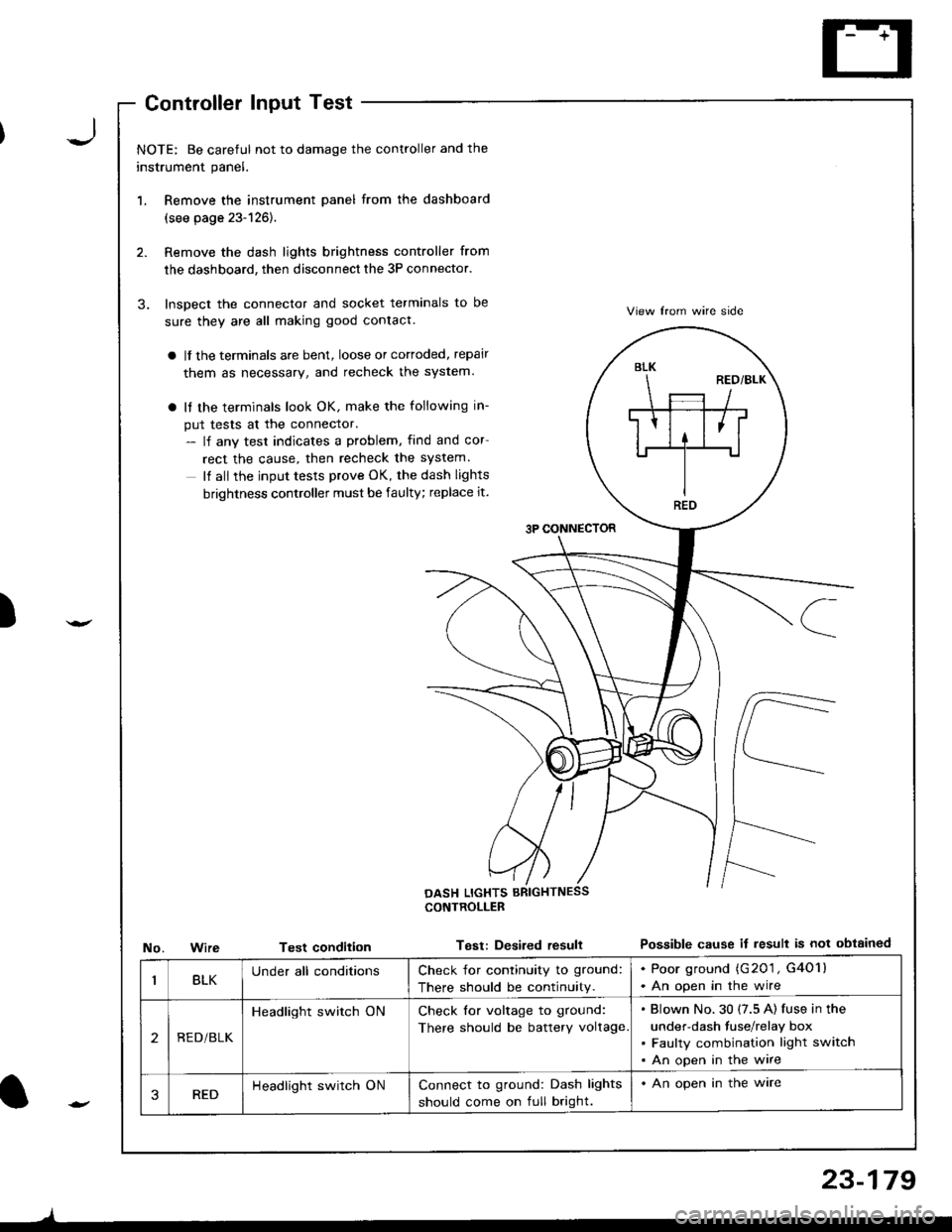
Remove the dash lights brightness controller from
the dashboard, then disconnect the 3P connector.
Inspect the connector and socket terminals to be
sure they are all making good contact.
a lf the terminals are bent, loose or cortoded, repair
them as necessary, and recheck the system.
a It the terminals look OK, make the following in-
put tests at the connector.- lf any test indicates a problem, find and cor
rect the cause, then recheck the system.
It all the input tests prove OK, the dash lights
brightness controller must be faulty; replace it.
3P CONNECTOR
View lrom wire side
Possible cause if result is not obtainedNo.WireTest condition
CONTROLLEB
Test: Desired resull
BLK
REO
BLKUnder all conditionsCheck for continuity to ground:
There should be continuity.
. Poor ground (G201 , G4O1l. An open in the wire
2REDi BLK
Headlight switch ONCheck for voltage to ground:
There should be battery voltage
Blown No.30 (7.5 A) fuse in the
under-dash fuse/relay box
Faulty combination light switch
An open in the wire
3REDHeadlight switch ONConnect to ground: Dash lights
should come on full bright.
. An open in the ware
l-
)
23-179
Page 1245 of 1681
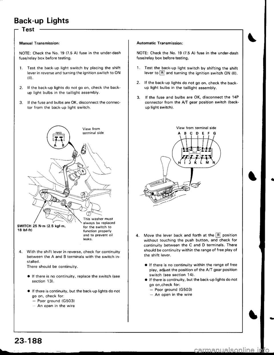
Back-up Lights
Test
Manual Transmission:
NOTE: Check the No. 19 (7.5 A) fuse in the underdash
fuse/relay box before testing.
Test the back-up light switch by placing the shift
lever in reverse and turning the ignition switch to ON
fl r).
lI the back-up lights do not go on, check the back-
up light bulbs in the taillight assembly.
lI the fuse and bulbs are oK, disconnect the connec-
tor from the back-up light switch.
2.
3.
l.
SWITCH 25 N.m (2.5 kgf-m,'18 lbf-Ir)
This washer mustalways be replacedfor the switch totunction properly
and 10 prevent oilteaKs,
terminal side
4. With the shift lever in reverse, check for continuity
between the A and B terminals with the switch in-
stalled.
There should be continuity.
a It there is no continuity, replace the switch (see
section 13).
a lf there is continuity, but the back-up lights do not
go on, check for:- Poor ground {G503}
An open in the wire
A
6
Automatic T.ansmission:
NOTE: Check the No. 19 (7.5 A) fuse in the under-dash
fuse/relay box before testing.
2.
'1 .Test the back-up light swirch by shifting the shiftlever to @ and turning the ignition switch ON (ll).
lf the back-up lights do not go on, check the back-
up light bulbs in the taillight assembly.
lf the fuse and bulbs are OK, disconnect the 14P
connector from the A,/T gear position switch (back-
up light switch).
View from terminal side
ABCDEFG
Move the lever back and torth at the E position
without touching the push button, and check for
continuity between the C and D terminals. There
should be continuity within the range of free play of
the shilt lever.
a lf there is no continuity within the range of free
play, adiusl the position ot the A/T gear position
switch {see section 14}.
a lf there is continuity, but the back-up lights do not
go on,check tor:- Poor ground {G5O3)- An open in the wire
Page 1247 of 1681
Brake
Brake
Lights
Switch TestHigh Mount Brake Light Replacement
\
t
2.
t.
3.
lf the brake lights do not go on. check the No. 52
{20 A) fuse in the under-hood fuse/relay box, and
the brake light bulbs in the taillight assembly and
high mount brake light.
lf the fuse and bulbs are OK, disconnect the 2P or
4P connector from the brake switch.
Without c.uisecontrol syst€mWilh cruisecontrol sYstem
Check for continuity between the B and C terminals.
There should be continuity with the brake pedal
pusneo.
a lf there is no continuity, replace the switch or ad-just pedal height (see section '19).
o It there is continuity, but the brake lights do not
go on, inspect for:
Poor ground (G5O3)
An open in the wire
AB
FS-A
lt--Ltl, t!,Z-\CD
-/Branl-ltl
tLatl\c
(LED typel
1. Remove the tour screws and the high mount brake
light, then disconnect the connectors.
TAILGATE SPOILER
HIGH MOUNT BRAKE LIGHT {tED TYPE}
23-190
Page 1251 of 1681
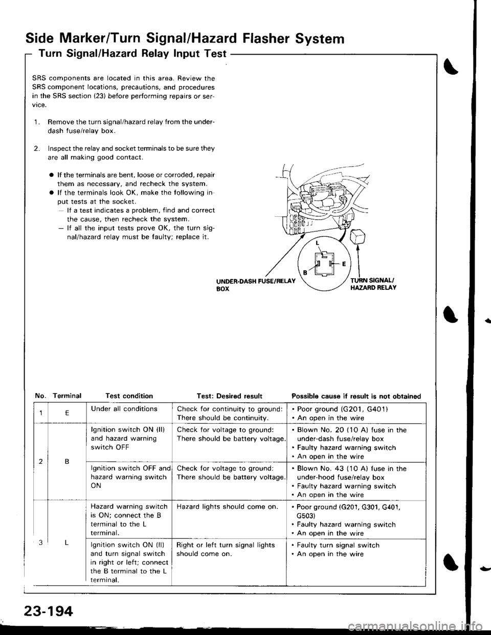
Side Marker/Turn Signal/Hazard Flasher System
Turn Signal/Hazatd Relay Input Test
\
t
SRS components are located in this area. Review the
SRS component locations, precautions, and procedures
in the SRS section (23) before performing repairs or ser-
1.Remove the turn signal/hazard relay from the under-
dash fuse/relay box.
Inspect the relay and socket terminals to be sure they
are all making good contact.
a lf the terminals are bent, loose or corroded, repair
them as necessary, and recheck the system.
a lf the terminals look OK, make the tollowing in
put tests at the socket.
lf a test indicates a problem, find and correct
the cause, then recheck the system.- lf all the input tests prove OK, the turn sig-
nallhazad relay must be faulty; replace jt.
2.
UiTDER.DASH FUSE/RELAYaox
TURN SIGNAL/HAZAND RELAY
No. Telminal Test conditionTest: Deaired resultPossible cause it result is not obtained
lgnition switch ON (ll)
and turn signal switch
in right or left; connect
the B terminal to the L
rermtnat,
Check for continuity to ground:
There should be continuity.
. Poor ground (G201, G401). An open in the wire
lgnition switch ON (ll)
and hazard warning
switch OFF
Check for voltage to ground:
There should be battery voltage
. Blown No. 20 ( 10 A) fuse in the
under-dash fuse/relay box. Faulty hazard warning switch. An open in the wire
lgnition switch OFF and
hazard warning switch
ON
Check lor voltage to ground:
There should be battery voltage.
. Blown No. 43 ('1 0 A) f use in the
under-hood fuse/relay box. Faulty hazard warning switch. An open in the wire
Hazard warning switch
is ON; connect the B
terminal to the L
rermtnat.
Hazard lights should come on.. Poor ground (G201, G301, G401,
cs03). Faulty hazard warning switch. An open in the wire
Right or left turn signal lights
should come on.
. Faulty turn signal switch. An open in the wire
Page 1257 of 1681
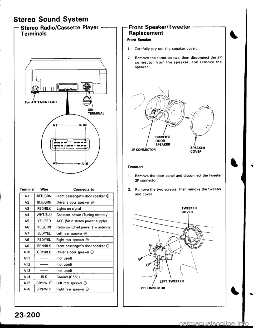
Stereo
Stereo
Sound System
Radio/Cassette PlayerFrontSpeaker/Tweeter
Replacement
Front Sp€aker:
'1. Carefully pry out the speaker cover.
2. Remove the three screws, then disconnect the 2P
connector from the speaker, and remove the
speaKer.
2P CONNECTOR
Tweoter:
1. Remove the door panel and disconn€ct the tweeter
2P connector.
2. Remove the two screws, then remove the tweeter
ano cover.
A
//1
\7
)-ISPEAKERCOVER
2P CONNECTOR
Terminals
T€rminalWireConnecta to
\
FoT ANTENNA LEAD
oIttFRMINAL
a9- -- -------> A 16
AIRED/GRNFront passenge.'s door speaker @
A2BLU/GRNDriver's door speaker O
A3RED/BLKLights-on signal
A4WHT/BtUConstant power (Tuning memory)
A5YEL/REDACC {Main stereo power supply)
A6YEL/GRNRadio switched power 1To antenna)
A7BLU/YELLeft rear speaker @
A8RED/YELRight rear speaker @
A9BRNi BLKFront passenger's door speaker O
A10GRY/BLKDriver's door speaker O
A11(not used)
{not used)
A13(not used)
A14 BLKGround {G551)
A15 GRY,ryVHTLeft rear speaker O
A168RN AVH TRight rear speaker O
23-200