Page 1154 of 1681
lgnition Control Module (lCM) Input Test
NOTE:
a See section 1 1 if the malfunction indicator lamp (MlLl
has been reported on.a Perform an input test for the ignition control module(lCM) after finishing the fundamental tests for the ig-nition system and the fuel and emissions systems.a The tachometer should operate normally.
1. Remove the distributo. ignition (Dl) cap, the rotor,and the leak cover.
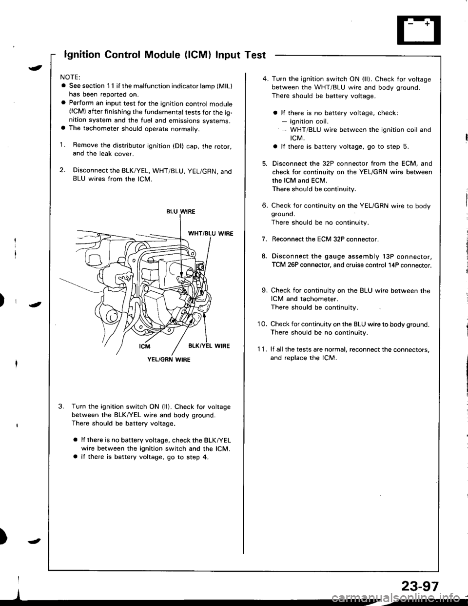
2. Disconnect the BLK/YEL, WHT/BLU, YEL/GRN, andBLU wires from the lCM.
3. Turn the ignition switch ON {ll}. Check for voltage
between the BLK/YEL wire and body ground.
There should be battery voltage.
a lf there is no battery voltage, check the BLKiYEL
wire between the ignition switch and the lCM.a It there is battery voltage, go to step 4,
)
I
)
BLU WIRE
YEL/GRN I,\'IRE
4. Turn the ignition switch ON (ll). Check for voltage
between the WHT/BLU wire and body ground.
There should be battery voltage.
a lf there is no battery voltage, check:- ignition coil.- WHT/BLU wire between the ignition coil and
tcM.
a lf there is battery voltage, go to step 5.
5. Disconnect the 32P connector from the ECM, and
check for continuity on the YEUGRN wire between
the ICM and ECM.
There should be continuity.
6. Check for continuity on the YEL/GRN wire to bodygrouno.
There should be no continuity.
7.Reconnect the ECM 32P connector.
Disconnect the gauge assembly 13P connector,
TCM 26P connector, and cruise control l4P connector.
9. Check for continuity on the BLU wire between the
ICM and tachometer.
There should be continuity.
'10. Check for continuity on the BLU wire to body ground.
There should be no continuity.
1 1 . lf all the tests are normal, reconnect the connectors,
and replace the lCM.
23-97
/i
Page 1160 of 1681
{From previous page}
Repai. ths open in tho WHT/ALUor BLK/YEL wir€.Does the charging systemlight come on?
Chock tor a sho.l in the L cir-cuit lcont'd):Disconnect the No.3 terminal ofthe 4P [3Pl connector from theground.
Does the charging systemlight go offi
Repair the shon to ground in thoWHT/BLU wiro.
{
t
Check for an opon in lhe L cir-cuit:1. Turn the ignition switch OFF.2. Disconnect the 4P connectorfrom the alternator.3. Ground the No. 3 terminal ofthe 4P [3Plconnector.4. Turn the ignition switch ON (ll).
ALTERNATOB irP CONNECTOR
ALTERNATOR 3PCONNECTOR {Canadal
11 2 3l
,l
iin"vr.rr\
Wire side oftemale t€rminals
[ ]: Canada
LIWHT/BLUI
LIWHT/BLU)
Wire side offemale terminals
)
23-103
4
--
Page 1161 of 1681
Gharging System
Troubleshooting
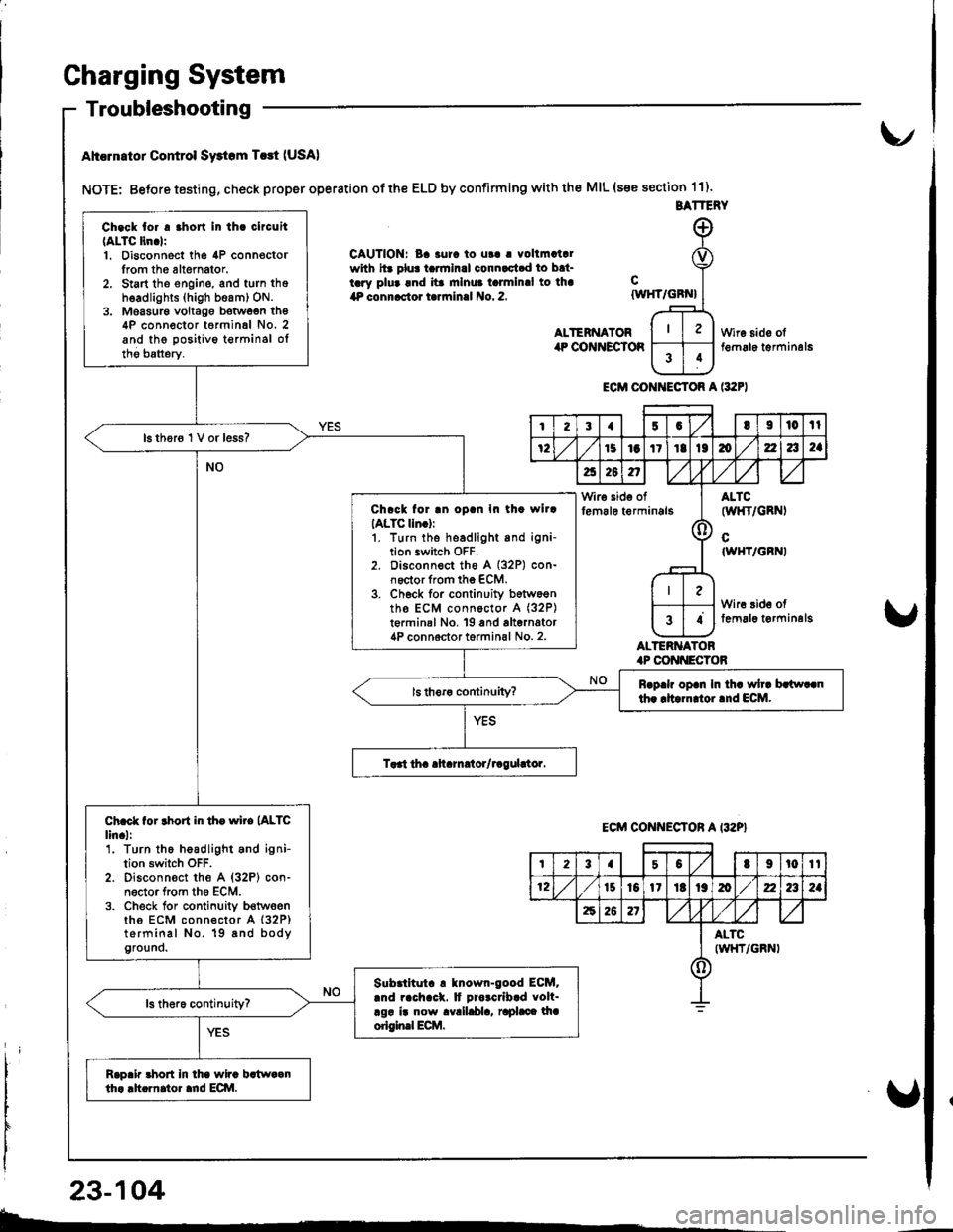
Ahcrn.tor Control Swtom T.rt (USA)
NOTE: Betore testing, check proper operation of the ELD by confirming with the MIL (s€e section 11).
CAUTION: Ba 3urc to ut! | vollmatalwith hr plu! tarmlnal connactad to bat-tary plua and ita mlnua talmlnal to lha4P connactor tarrninal No. 2.
ALTENNATORilP COiINECTOR
cIWHT/GBN}
ALTERNATOR.P CONI{ECTOB
Wire sido olt€m6le t€rminal6
ECM CONI{ECTOR A l:t2F)
BATTERY
Ch.ck tor . .hort In th. clrcuit(ALTC ltn.lr1. Disconnect the 4P connoctorIrom th6 altemator.2. Start tho engine, and turn thoh6adlights (high beam) ON.3. Moasur€ voltago botwoen th64P conn€ctor t6rminal No. 2and the positivo t€rminsl oltho batterv.
16 thor6 1 V or less?
Chrck for .n oD.n In th. wllrIALTC lln.):1. turn the headlight and igni-tion switch OFF.2. Disconnect th6 A (32P) con-noctor from the ECM.3. Ch6ck for continuity b6tw6entho ECM connoctor A (32P)
t€rminal No, 19 and alternator4P connoctor torminal No. 2.
Rrp.h op.n In th. wh. brlw..nth. rltarn oi.nd ECM.
Ch.ct for rhort in th. wire (ALTC
lin.l:'1. Turn the headlight and ignition switch OFF.2. Disconn€ct the A {32P} con-n6ctor from tho ECM.3. Check for conlinuity b€twoenths ECM connector A (32P)
terminal No. 19 8nd bodyground.
Slbrlltut. ! tnown-good ECM..nd rach.ck. It Drorcrlb.d volt-rgr ir now avalldla, raphce lhaorigin.l Ecilt.
Rap.ir 3hort in lha wira bstwaanth. .h.rnator ard ECI\|.
I23{5GtI|l0tl
72151aItIt136zla2a
a26n,/,V
Wir€ side offem6le t€rminals(l
ALTC(wl{T/GRNI
cIWHT/GBNI
Wire 3id€ offemal6 t€rminelg34
ECM CONNECTON A I32P}
t23a50t9t0tt
12t510l1Itt9mz2a2a
62621
ALTCIWHT/GRNI()
23-104
b-.
Page 1162 of 1681
{
t
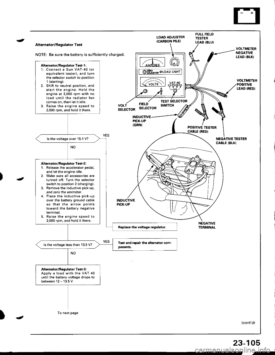
Alternator/Regulator Test
NOTE: 8e sure the battery is sufficiently charged.
LOAO ADJUSTER
ICARBON PILE)
FULL FIELDTESTERT.EAD (8LU)
POSITIVE TESTERCABLE IREDI
NEGATIVETERMINAL
VOLTMETERNEGATIVELEAO {BL|(}
VOLTMEIERPOSmVELEAD IREDI
FIELOSELECTOR
TEST SELECTORswtTcHVOLTSELECTOR
INDUCTIVEPICK.UP
INDUCTIVEPICK.UPIGRNI
NEGANVE TESTERCABLE IBLKI
)
)
{cont'd)
23-105
Ahernator/Regulator Tosl-1 :1. Connect a Sun VAT-40 (or
equivalent testerl, and turnthe selector switch to position'1 (starting).
2. Shift to neutral position, andstart the engine. Hold theengine at 3,000 rpm with noload until the radiator tancomes on, thon let it idle.3. Raise the engine sp€ed to2,000 rpm, and hold it there.
ls the voltage over 15.1 V?
Altsrnator/Rogulator Test-z:1. Release the accelerator pedal,
and let the engine idle.2, Make sure all accessories areturnod off. Turn the selectorswitch to position 2 (charging).
3. Remove the inductive pick-up,
and zero the ammeter.4. Place the inductive pick-up
over the battery ground cableso that the arrow points
toward the batterY negativeterminal,5. Raise the engine speed to2.000 rpm, and hold it there.
ls the voltage less than 13.5 V?
Ahelnstor/Regulator T$t-3iApply a load with the VAT-40until the battery voltage drops tobetween 12 - 13.5 V.
To next page
-
i-
Page 1163 of 1681
From previol.rs page
The charging swtem is OK.lsthe amperage 70 A or more?
Alternator/Regulator Test-4:With the engine speed still at2,000 rpm, Iull-Iield the alternator.
Charging System
Troubleshooting (cont'dl
CAUTION: Th6 voltago will rise quickly when the ahernator is ful!fieldcd. Do not .llowth6 voltag€ to €xc6ed 18 V; it may damage tho ol6drical system.
NOTE: Attach a probe to the VAT'40 full field test lead, and insert the probe into the lullfield access hole at the back of the alternator. Switch the field selector to the "A {Ground}"position momentarily, and check the amperage reading.
REGULATOB(Located inside
FULL FIELOACCESS HOLE
END COVEB
END COVER
FULL FIELDACCESS HOLE
L^
23-106
Page 1164 of 1681
Alternator Replacement
)
t
-
NOTE: The original radio has a coded theft protection
circuit. Be sure to get the customer's code number before
- disconnecting the battery.
- removing the No. 47 (7.5 A) fuse from the under-hood
fuse/relay box.
removing the radio.
After service, reconnect power to the radio and turn it on.
When the word "CODE" is displayed, enter the cus
tomer's s-digit code to restore radio operation.
1. Disconnect the ground cable from the battery nega-
tive (- ) terminal.
2. Disconnect the alternator connector from the al-
lernalor,
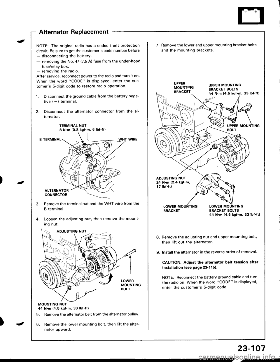
TERMINAL NUT8 N,m (O.8 kgf'm, 6 lbl'ft)
B TERMINAL
ALTERNATORCONNECTOR
Remove the terminal nut and the WHT wire from the
B terminal.
Loosen the adjusting nut, then remove the mount-
Ing nut.
MOUNTINGBOLT
MOUNTING NUT44 N.m (4.5 kgf.m.33 lbt.ftl
5. Remove the alternator belt from the alternator pulley.
6. Remove the lower mounting bolt, then lilt the alter-
naror upwaro.
3.
{--,
7.Remove the lower and upper mounting bracket bolts
and the mounting brackets.
BRACKET BOLTSil4 N.m {4.5 kgl.m, 33 lbt.ft)
8. Remove the adiusting nut and upper mounting bolt,
then lift out the alternator.
9. lnstallthe alternator in the reverse order of removal.
CAUTION: Adiust the alternator belt tension aftsr
installation lseo page 23-1151.
NOTE: Reconnect the battery ground cable and turn
the radio on. When the word "CODE" is displayed,
enter the customer's s-digit code.
BRACKET
UPPER MOUNTINGBRACKET EOLTS44 N.m {4.5 kgl.m, 33 lbl'ft)
24 N.m (2.4 kgf.m,17 rbf.ftl
b-h..K
) I
23-107
-
,-
Page 1166 of 1681
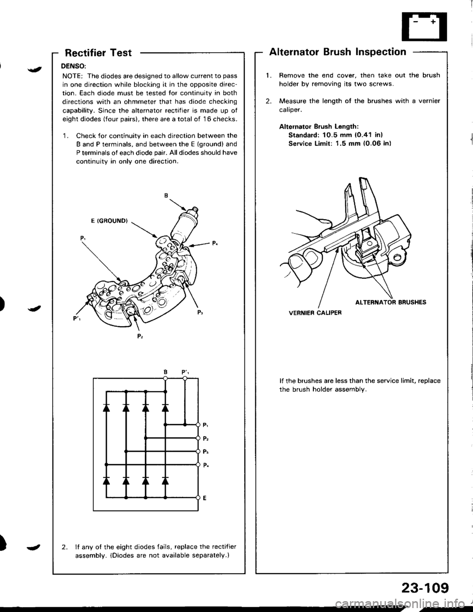
RectifierTest
DENSO:
NOTE: The diodes are designed to allow current to pass
in one direction while blocking it in the opposite direc-
tion. Each diode must be tested tor continuity in both
directions with an ohmmeter that has diode checking
capability. Since the alternator rectifier is made up ot
eight diodes (four pairs), there are a total of 16 checks.
'1. Check for continuity in each direction between the
B and P terminals, and between the E (ground) and
P terminals of each diode pair. All diodes should have
continuity in only one direction.
lf any of the eight diodes fails, replace the recti{ier
assembly. iDiodes are not available separately.)
2.
AlternatorBrushInspection
l.Remove the end cover, then take out the brush
holder by removing its two screws.
Measure the length of the brushes with a vernier
caliper.
Altelnator Brush Length:
Standard: 1O.5 mm {O.41 in}
Service Limit: 1.5 mm (0.06 in)
2.
lf the brushes are less than the service limit, replace
the brush holder assembly.
VERNIER CALIPER)
{
J
)
23-109
J
.-
Page 1169 of 1681
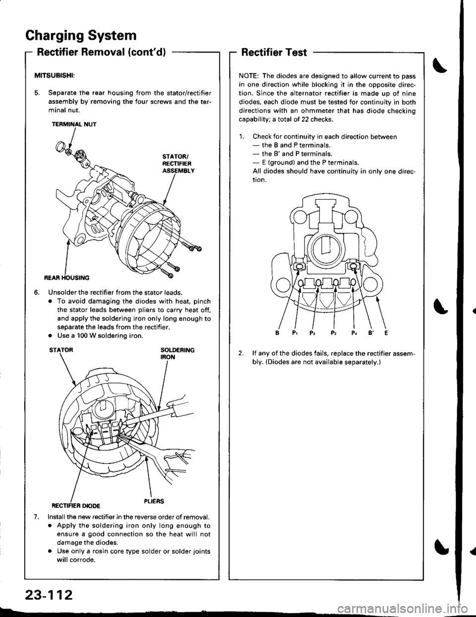
Gharging System
Reetifier Removal (cont'd)
MITSUBISHI:
5. Separate the rear housing from the stator/rectifier
assembly by removing the four screws and the ter-
minal nut.
6.
1.
Unsolder the rectifier from the stator leads.
. To avoid damaging the diodes with heat, pinch
the stator leads between pliers to carry heat off,
and apply the soldering iron only long enough to
separate the leads from the rectifier.
. Use a 100 W soldering iron.
Installthe new rectifier in the reverse order of removal.
. Apply the soldering iron only long enough to
ensure a good connection so the heat will not
damage the diodes.
. Use only a rgsin core type solder or solder joints
will cor.ode.
RectifierTest
NOTE: The diodes are designed to allow current to pass
in one direction while blocking it in the opposite direc-
tion. Since the alternator rectifier is made up of nine
diodes, each diode must be tested for continuity in both
directions with an ohmmeter that has diode checkino
capability; a total of 22 checks.
1. Check for continuity in each direction between- the B and P terminals.- the B' and P terminals,- E (ground) and the P terminals.
All diodes should have continuity in only one direc-
uon.
2.lf any of the diodes fails, replace the rectifier assem-
bly. (Diodes are not available separately.)
b.�
23-112
{