1998 HONDA INTEGRA light
[x] Cancel search: lightPage 66 of 1681

Valve Clearance
Adjustment (cont'dl
Adjust valve clearances on No. 1 cylinder.
Intske: 0.08 - 0.12 mm (0.003 - 0.005 inl
Exhaust: 0.15 - 0.20 mm (0.006 - 0.008 inl
Loosen the locknut and turn the adjusting screw
until feeler gauge slides back and forth with a slight
amount of drag.
7. Rotate the crankshaft 180' counterclockwise to
bring No. 4 piston to TDC. The "UP" mark should
be pointing straight down. Adjust valves on No. 4
cylinder.
Number 4 piston at TDC:
LOCKNUT9x0.75mm25 N.m {2.5 kgl.m, 18lbtft}
Tighten the locknut and recheck clearance again,
Repeat adjustment if necessary.
Rotate the crankshaft 180' counterclockwise(camshaft pulley turns 90'). The "UP" mark should
be on the exhaust side. Adjust valves on No,3 cylin-
der.
8. Rotate the crankshaft 180' counterclockwise to
bring No. 2 piston to TDC. The "UP" mark should
be on the intake side. Adjust valves on No. 2 cylin-
der.
Number 2 piston at TDC:
Number 3 Diston at TDC:
NOTE: Refer to page 6-31 when installing cylinder head
cover.
"UP" MARKS
"UP" MARKS
"UP" MARKS
Page 88 of 1681

Valve Installation'alve Inslallauon -
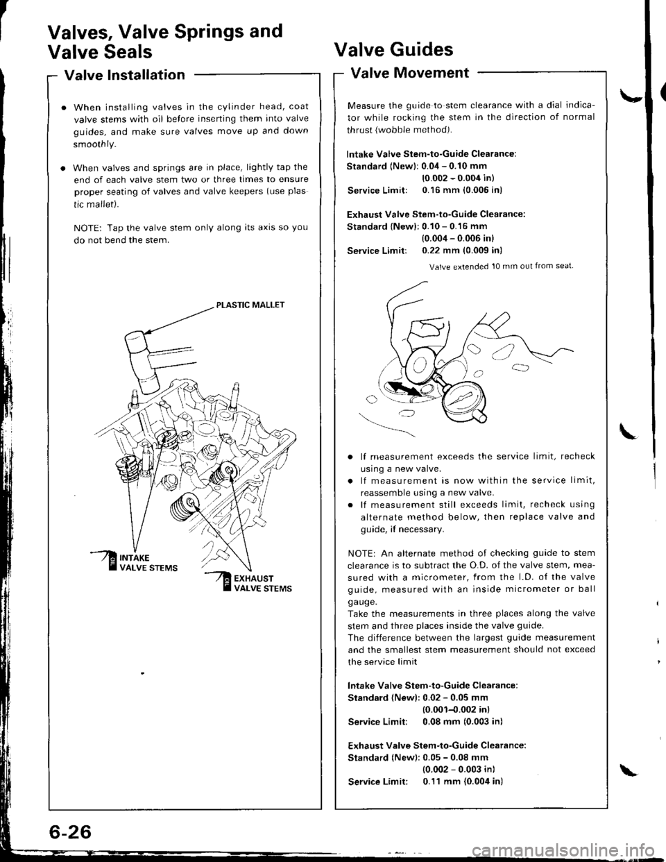
When installing valves in the cylinder head, coat
valve stems with oil belore inserting them into valve
guides, and make sure valves move up and down
smoothly.
When valves and springs are in place, lightly tap the
end of each valve stem two or three times to ensure
proper seating of valves and valve keepers (use plas
tic mallet).
NOTE: Tap the valve stem only along lts axrs so you
do not bend the stem.
PLASTIC MALLET
Valves, Valve Springs and
Valve SealsValve
Valve
Guides
Movement
\-
L
valve tvtovemenr -
Measure the guide to stem clearance with a dial indica-
tor while rocking the stem in the direction of normal
thrust {wobble method).
lntake Valve Stem-to-Guide Clearance:
Standard {Newlr 0.04 - 0.10 mm
10.002 - 0.004 in)
Service Limit: 0.16 mm {0.005 in)
Exhaust Valve Stem-to-Guide Clearance:
Standard {New}: 0.10 - 0.16 mm
(0.004 - 0.006 inl
Service Limit: 0.22 mm (0.009 in)
Valve extended 10 mm out from seat
lf measurement exceeds the service limit, recheck
usrng a new valve.
lf measurement is now within the service limit,
reassemble using a new valve.
lf measurement still exceeds limit, recheck using
alternate method below, then replace valve and
guide, if necessary.
NOTEr An alternate method of checking guide to stem
clearance is to subtract the O.D. of the valve stem, mea-
sured with a micrometer, from the l.D. o{ the valve
guide, measured with an inside micrometer or ball
ga uge.
Take the measurements in three places along the valve
stem and three places inside the valve guide.
The diiference between the largest guide measurement
and the smallest stem measurement should not exceed
the service limit
lntake Valve Stem-to-Guide Clearance:
Standard (Newl: 0.02 - 0.05 mm
10.001-{.002 inl
Service Limit: 0,08 mm (0.003 in)
Exhaust Valve Stem-to-Guide Clearance:
Standard (New): 0.05 - 0.08 mm
{0.002 - 0.003 in)
Service Limit: 0.11 mm {0.004 in)\
Page 91 of 1681

\
Valve Seats
Reconditioning
ACTUALSEATINGSURFACE
VALVESEAT
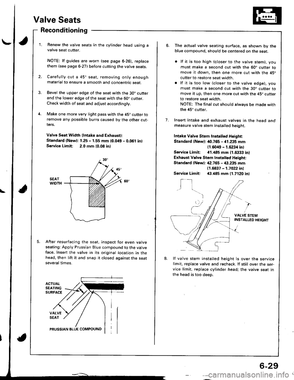
Renew the valve seats in the cylinder head using avalve seat cutter.
NOTE: lf guides are worn (see page 6-26), replace
them {see page 6-27) before cutting the valve seats.
Carefully cut a 45" seat, removing only enoughmaterial to ensure a smooth and concentric seat.
Bevel the upper edge of the seat with the 30. cutterand the lower edge of the seat with the 60. cutter.Check width of seat and adjust accordingly.
Make one more very light pass with the 45o cutter toremove any possible burrs caused by the other cut-rers.
V8lv6 S€at Width (lntake and Exhaustl:
Standard {New}: 1.25 - 1.55 mm {0.0/t{, - 0.061 in}
S€rvice Limit: 2.0 mm 10.08 in)
After resurfacing the seat, inspect for even valveseating: Apply Prussian Blue compound to the valveface. Insert the valve in its original location in thehead, then lift it and snap it closed against the seatseveral times.
PRUSSIAN BLUE COMPOUNO
6-29
o.The actual valve seating surface, as shown by theblue compound, should be centered on the seat.
lf it is too high (closer to the valve stem), you
must make a second cut with the 60" cutter tomove it down, then one more cut with the 45"
cutter to restore seat width.
lf it is too low (closer to the valve edge), you
must make a second cut with the 30. cutter tomove at up, then one more cut with the 45. cutterto restore seat width.
NOTE: The final cut should always be made with
the 45" cutter.
Insert intake and exhaust valves in the head andmeasure valve stem installed height.
Intake Valve Stem Inst8lled Height:
Standard lN6wl: 40.765 - i11.235 mm(1.6049 - 1.6234 in)
Servico Limiti i01.,|85 mm (1.6333 in)
Exhaust Valv€ Stem Installed Height:
Standard {Newl: ,[2.765 - 4:1.235 mm
1.
{1.68i}7 - 1.7022 inl,(1.485 mm 11.7120 inlService Limit:
I_1I
VALVE STEMINSTAI-LED HEIGHT
8.lf valve stem installed height is over the servicelimit, replace valve and recheck. lf still over the ser-vice limit, replace cylinder head; the valve seat in
the head is too deep.
Page 96 of 1681

Cylinder Head
Installation (cont'dl
19. When installing the cylinder head cover. hold the
rubber seal in the groove by placing your fingers on
the camshaft holder contacting surfaces (top of the
semicircles).
Once the cylinder head cover is on the cylinder
head, slide the cover slightly back and iorth to seat
the rubber seal.
NOTE:
. Before installing the cylinder head cover, clean
the cylinder head contacting surfaces using a
shop towel.
. Do not touch the parts where liquid gasket was
applied.
6x1.0mm9.8 N.m {1.0 kgf.m,7 .2 tblltl
6-34
\
21.
Tighten the nuts in 2 or 3 steps. In the final step,
tighten ali nuts, in sequence, to 9.8 N'm (1.0 kgim,
7.2 tbf.ft).
After installing, check that all tubes, hoses and con-
nectors are installed correctly.
Page 159 of 1681

11
Bore Honing
l/easure cylinder bores as shown on page 7-14.lf the block is to be reused, hone the cylinders andremeasure the bores.
Hone cylinder bores with honing oil and a fine (400
grat) stone in a 60 degree cross-hatch pattern.
NOTE:
. Use only a rigid hone with 400 grit or finer stonesuch as Sunnen, Ammco, or equivalent.a Do not use stones that are worn or oroKen.
When honing is complete, thoroughly clean thecylinder block of all melal particles. Wash the cylin-der bores with hot soapy water, then dry and oilimmediately to prevent rusting.
NOTE: Never use solvent, it wili only redistribute
the grit on the cylinder walls.
lf scoring or scratches are still present in cylinderbores after honing to the service limit, rebore theengine block.
NOTE: Some light vertical scoring and scratching isacceptable if it is not deep enough to catch your fin-gernail and does not run the full length ofthe bore.
NOTE:
. After honing, clean the cylinder thoroughly withsoapy water.o Only scored or scratched cylinder bores must behoned.
4.
7-15
Page 173 of 1681

Oil Seal
Installation
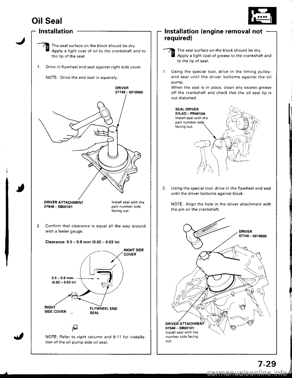
The seal surface on the block should be dry.
Apply a light coat of oil to the crankshaft and
the lip of the seal.
1. Drive in tlywheel end seal against right side cover.
NOTE: Drive the end seal in squarely.
DRIVER07749 - 0010000
Confirm that clearance is equal all the way around
with a feeler gaug€.
Clearance: 0.5 - 0.8 mm {0.02 - 0.03 inl
RIGHT SIDECOVER
lnstallation (engine removal not
requiredl
The seal surface on the block should be dry.
Apply a light coat of grease to the crankshaft and
to the lip of seal.
1. Using the special tool, drive in the timing pulley-
end seal until the driver bottoms against the oil
pump.
When the seal is in place, clean any excess grease
off the crankshalt and check that the oil seal lip is
not distoned.
SEAL DRIVER07LAD. PR4O1OAlnstall seal with thepan numberfacing out.
Using the special tool, drive in the flywheel end seal
untilthe driver bottoms aqainst block.
NOTE: Align the hole in the driver attachment with
the pin on the crankshaft.
DRIVER077{9 - 0010000
DRIVER ATT07948 - 5800101lnstall sealwith thenumber side facinqou!.
'tvA,)/ )
DBIVER ATTACHMENT07948 - 5800101Install sealwith thepan number sidefacang out.
[7Fd
NOTE: Refer to right column and 8-11
tion of the oil pump side oil seal.
for installa-
Page 180 of 1681

Oil Filter
Replacement
CAUTION: After the engine has been run, the exhaustpipes will be hot; be careful when working around theexhaust manitold.
Re m ove the
wrench.
Iilter with the speciallilter
API CERTIFICATION MARK
API SERVICE LABEL
The numbers in the middle of the Apl Service tabelyou the oil's SAE viscosity or weight. Selecr rhe oilyour vehicle according to this chart:
Inspect the threads and rubber seal on the new fil-ter. Wipe oif seat on engine oil cooler, then apply alight coat ol oil to the filter rubber seal.
NOTE: Use only filters with a built-in bypass system.
Inspect threads andrubber seal surface.
tell
for
Ambi€nt Temperature
An oil with a viscosity of 5 W 30 is preferred forimproved fuel economy and year-round protection inthe vehicle.
You may use a 10 W 30 oil if the climate in your area islimited to the temperature range shown on the chart.
4. Run the engine for more than three minutes, thencheck for oil leakage and oil level.
Apply oilto.ubber sealbefore installing.-to20-30
{cont'd)
8-7
Page 182 of 1681

Oil Pressure
Testing
lf the oil pressure warning light stays on with the enginerunning, check the engine oil level. It the oil level iscorrect:
Connect a tachometer.
Remove the oil pressure switch and install an oil pressure gauge.
Start the engine. Shut it off immediately if the gaugeregasters no oil pressure. Repair the problem beforecontinuing.
Allow the engine to reach operating temperature (fan
comes on at least twicel. The pressure should be:
Engine Oil Pressure:
At ldle: 70 kPa {O.7 kgficmr, tO psil
minimum
At 3,OOO rpm: 34O kPa (3.5 kgf/cmr, 50 psil
minimum
a lf oilpressure is within specifications, replace theengine oil pressure switch and recheck.
a lf oil pressure is NOT within specifications,rnspect the oil pump (see page g-11).
l�
2.
Oil Jet
lnspection(818C1, 818C5 engines
only)
1. Remove the oil jet (see pages 8 4 or 8 5) and inspectit as follows.
a Make sure rhat a 1 .1 mm (O.04 in) diameter drillwillgo through the nozzle hole fl.2 mm (O.O5 in)diameter).
a Insert the other end of the same 1 .1 mm {0.O4in) drill into the oit intake (1.2 mm (0.05 in)diameter).
Make sure the check ball moves smoothly and hasa stroke of approximately 4.0 mm (O.16 in).a Check the oil jet operation with an air nozzle. ltshould take at least 2OO kPa 12.O kg|lcm2, 2gpsi) to unseat the check ball.
NOTE: Replace the oiljet assembly if the nozzleis damaged or bent.
2. Mounting torque is critical. Be very precise when in-stalling.
Torque: 16 N.m (1.6 kgf.m, 12 lbf.ftl
1.2 mm (0.05 inl
16 N.m {1.6 kgf'm, 12 lbf.ftl
8-9