1998 HONDA INTEGRA height
[x] Cancel search: heightPage 85 of 1681

\-
Valves, Valve Springs
and Valve Seals
Removal
NOTE: ldentify valves and valve springs as they areremoved so that each item can be reinstalled in its origi-nal position.
1. Tap e€ch valve stem with a plastic mallet to loosen
valve keepers before installing the spring compres-sor.
Install the spring compressor. Compress spring andremove valve keeper.
VALVE SPRING COMPRESSORKD No.383, with #35 JAW orSnap-on CF711
Measure cam Iobe height.
Cam Lobe Height Standard (Newl
fNTAKE: 33.716 mm 11.3271inl
EXHAUST: 33.528 mm (1.3200 inl
\
\
VALVE SPRING COMPRESSORATTACHMENT07757 - PJ1010A
Inspect this area for wear.
;;:'
, -:.. "
'orl
._vn-'r'.'i),
I
6-23
Page 91 of 1681

\
Valve Seats
Reconditioning
ACTUALSEATINGSURFACE
VALVESEAT
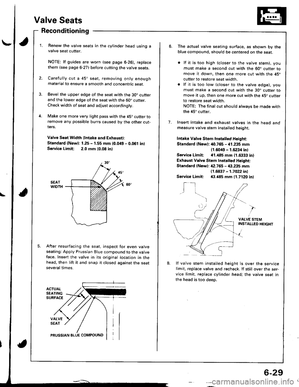
Renew the valve seats in the cylinder head using avalve seat cutter.
NOTE: lf guides are worn (see page 6-26), replace
them {see page 6-27) before cutting the valve seats.
Carefully cut a 45" seat, removing only enoughmaterial to ensure a smooth and concentric seat.
Bevel the upper edge of the seat with the 30. cutterand the lower edge of the seat with the 60. cutter.Check width of seat and adjust accordingly.
Make one more very light pass with the 45o cutter toremove any possible burrs caused by the other cut-rers.
V8lv6 S€at Width (lntake and Exhaustl:
Standard {New}: 1.25 - 1.55 mm {0.0/t{, - 0.061 in}
S€rvice Limit: 2.0 mm 10.08 in)
After resurfacing the seat, inspect for even valveseating: Apply Prussian Blue compound to the valveface. Insert the valve in its original location in thehead, then lift it and snap it closed against the seatseveral times.
PRUSSIAN BLUE COMPOUNO
6-29
o.The actual valve seating surface, as shown by theblue compound, should be centered on the seat.
lf it is too high (closer to the valve stem), you
must make a second cut with the 60" cutter tomove it down, then one more cut with the 45"
cutter to restore seat width.
lf it is too low (closer to the valve edge), you
must make a second cut with the 30. cutter tomove at up, then one more cut with the 45. cutterto restore seat width.
NOTE: The final cut should always be made with
the 45" cutter.
Insert intake and exhaust valves in the head andmeasure valve stem installed height.
Intake Valve Stem Inst8lled Height:
Standard lN6wl: 40.765 - i11.235 mm(1.6049 - 1.6234 in)
Servico Limiti i01.,|85 mm (1.6333 in)
Exhaust Valv€ Stem Installed Height:
Standard {Newl: ,[2.765 - 4:1.235 mm
1.
{1.68i}7 - 1.7022 inl,(1.485 mm 11.7120 inlService Limit:
I_1I
VALVE STEMINSTAI-LED HEIGHT
8.lf valve stem installed height is over the servicelimit, replace valve and recheck. lf still over the ser-vice limit, replace cylinder head; the valve seat in
the head is too deep.
Page 92 of 1681

Cylinder Head
Wapage
NOTE: lf camshaft-to-holder oil clearances (see page 6
22) arc nol within specification, the head cannot be
resurfaced.
lf camshaft-to-holder oil clearances are within specifica-
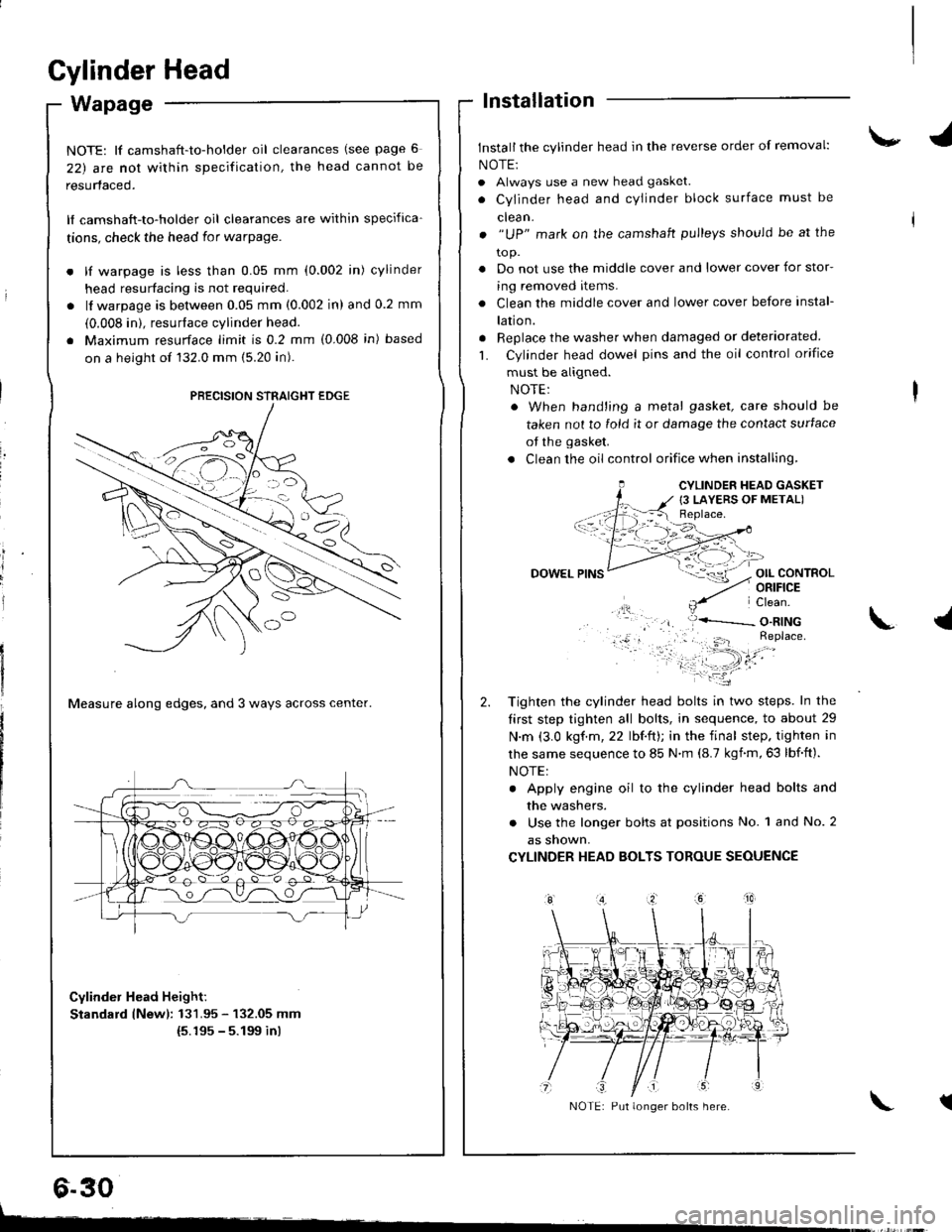
tions, check the head for warpage.
lf warpage is less than 0.05 mm (0.002 in) cylinder
head resurfacing is not required.
lf warpage is between 0.05 mm (0.002 in) and 0.2 mm
(0.008 in). resurface cylinder head.
Maximum resurface limit is 0.2 mm (0.008 in) based
on a height of 132.0 mm (5.20 in).
Measure along edges, and 3 ways across center.
Cylinder Head Height:
Standard lNewl: 131.95 - 132.05 mm(5.195 - 5.199 inl
lnstallation
Install the cylinder head in the reverse order of removal:
NOTE:
. Always use a new head gasket.
. Cylinder head and cYlinder block surface must be
clean.
. "UP" mark on the camshaft pulleys should be at the
to p.
. Do not use the middle cover and lower cover for stor-
ing removed items.
. Clean the middle cover and lower cover before instal-
lation.
. Replace the washer when damaged or deteriorated
L Cylinder head dowel pins and the oil control orifice
must be aligned.
. When hand'ing a metal gasket, care should be
taken not to fold it or damage the contact surface
of the gasket.
. Clean the oil control orifice when installing,
OIL CONTROLORIFICE
PRECISION STRAIGHT EDGE
6.30
CYLINDER HEAD GASKET
{3 LAYERS OF METAL)
DOWEL
Tighten the cylinder head bolts in two steps. In the
tirst step tighten all bolts, in sequence, to about 29
N.m (3.0 kgf.m,22 lbf.ft); in the final step. tighten in
lhe same sequence to 85 N.m (8.7 kgnm,63 lbf.ft).
NOTE:
. Apply engine oil to the cylinder head bolts and
the washers.
. Use the longer bolts at positions No. 1 and No. 2
as snown,
CYLINDER HEAD BOLTS TOROUE SEOUENCE
\.l
tNOTE: Put longer bolts here.
t-
Page 203 of 1681

Thermostat
Replacement
NOTE: Use new gaskets and O-rings when reas'
sembling.
GROUNDTERMINAL
6 x 1.0 mm12 N.m {1.2 kgt.m,8.7 lbf.ft)
THERMOSTATInstall with pin up.O RINGReplace
ECT SWITCH27 N.m {2.8 kgf.m, 20 lbf.ftl
J
1.
Replace _thermostat if it as open at room temperature.
To test a closed thermostat:
Suspend the thermostat in a container of water as
shown.
Heat the water and check the temperature with a
thermometer. Check the temperature at which the
thermostat lirst opens and at full litt.
CAUTION: Do not let the ihermometer touch the
bottom of the hot container.
Measure the lilt height of the thermostat when it's
fully open.
STANDARD THERMOSTAT
Lift height: above 8.0 mm (O.31 inr
Stalts opening: 169- 1760 F (76-8OoC)
Fully open: 194o F l9OoCl
THERMOMETER
THERMOSTAT
2.
3.
10-g
. )
Page 361 of 1681

Clutch Pedal
Adjustment
NOTE:
a To check the clutch interlock switch and clutch
switch, see section 23.
a The clutch is self-adjusting to compensate Ior wear.
CAUTION: ll there is no clealance between the master
cylinder piston and push rod, the release bearing is held
against the diaphragm spring, which can result in clutch
slippage or other clutch problems.
1. Loosen locknut A, and back off the clutch switch
(or adjusting bolt) until it no longer touches the clutch
peoal.
2. Loosen locknut C. and turn the push rod in or out
to get the specified stroke (@) and height {O) at the
clutch Dedal.
3. Tighten locknut C.
4. Turn the clutch switch (or adjusting bolt) until it con-
tacts the clutch pedal.
ASSIST SPRING
@{
{PiN 08798-9002t
(STROKE at PEDAL): 130-140 mm (5.12-5.51 in){TOTAL CLUTCH PEDAI- FREE PLAYI: 12-21 mm (0.47-0.83 inl including tho p6dal play{CLUTCH PEDAL HEIGHT): 164 mm 16.46 inl to the tloor(CLUTCH PEDAL DISENGAGEMENT HEIGHTI: 83 mm {3.27 inl minimum to the floo.
t?
5.Turn the clutch switch (or adjusring bolt) in 3/4 to
1 full turn further.
Tighten locknut A.
Loosen locknut B on the clutch interlock switch.
Measure the clearance between the floor board and
clutch pedal with the clutch pedal tully depressed.
Release the clutch pedal 15-20 mm (O.59-O.79
in) from the fully depressed position and hold it there.
Adjust the position of the clutch interlock switch so
that the engine will stan with the clutch pedal in this
position.
Turn clutch interlock switch 3/4 to 1 full turn further.
Tighten locknut B.
9.
6.
7.
8.
10.
11.
LOCKNUT B9.8 N.m 11.0 kgt.m, 7 lbl.ft)
CLUTCH INTERLOCKswrTcHPUSH ROD
CLUTCH MASTER CYLINDER
CLUTCH SWITCH(or AOJUSTING BOLT)
LOCKNUT A9.8 N.m (1.0 kgf.m, 7 lbt.frl
l
{P/N 0879a-9002)
12-4
1- 10 mm (0.O4-O.39 inl
Page 364 of 1681

Pressure Plate
Removal/lnspectaon
1. Check the diaphragm spring fingers for height us-
ing the special tools and a feeler gauge.
Standsrd (New): 0.6 mm (0.02 in) max.
Service Limit: 0.8 mm {0.03 in)
07NAF-PR3010007936-3710100
lf the height is more than the service limit, replacethe hro..rr.a nlefe
2. Install the special tools.
CLUTCH ALIGNMENT SHAFT07NAF -PR30100
HANDLE
RING GEAR HOLDER07LAB- PVOo'l0O oro7924-PD20003
07936 - 3710100
PRESSURE PLATE
GEAR HOLDER
ADJUSTER NUT
3.
ADJUSTER BOLT
BOLT
WASHER
To prevent warping, unscrew the pressure plate
moi.rnting bolts in a crisscross pattern in several
steps, then remove the pressure plate.
FEELER GAUGECLUTCH ALIGNMENT DISCOTJAF_PM7011A
5.
6.
Inspect the pressure plate surface for wear, cracks,
and burning.
Inspect the fingers of the diaphragm spring for wear
at the release bearing contact area.
DIAPHRAGM SPRING
PRESSURE PLATE
Inspect for warpage using a straight edge and teel-
er gauge.
NOTE: Measure across the pressure plate at three
points.
Standard {New}: 0.03 mm {0.001 inl max.
Service Limit:0.15 mm (0.006 in)
lf the warpage is more thah the service limit,
replace the pressure plate.
STRAIGHT EDGE
2-7
Page 368 of 1681

Release Bearing
Removal/lnspection
1. Remove the release fork
housrng.
boot from the clutch
5.
6.
Torque the mounting bolts in a crisscross pattern as
shown. Tighten the bolts in several steps to prevent
warping the diaphragm spring.
8 x 1.25 mm25 N.m {2.6 kgf.m,19 tb{.fr}
Remove the special tools.
Recheck the diaphragm spring fingers for height {seepage 12-7).
CLUTCH HOUSING
BELEASE AEAFING
RELEASE FORK
Remove the release fork from the clutch housing by
squeezing the release fork set spring with pliers. Re
move the release bearing.
Check the release bearing for play by spinning it by
hand. lf there is excessive play, replace the release
bearing with a new one.
CAUTION: The release bearing is packed wirhgrease. Do not wash it in solvent.
a;;;:
S",€ r
K4IN/
RELEASE BEARING
Page 707 of 1681

Power Steering Gearbox
Reassembly (cont'dl
63. Install new boot bands on the boot and bend both
sets of locking tabs.
Lightly tap on the doubled-over portions to reduce
their height.
CAUTION: Stake ihe bsnd locking tabs tirmly.
Slide the rack right and ieft to be certain that the
boots are not deformed or twisted.
Install the right and left tie-rod ends on the rack
enos.
64.
lnstallation
CAUTION: Bo caretul not to bond or damrge the powcr
steering lines when in3t8lling the grlrbox.
1. Before installing the gearbox, slide the rack all the
way to right.
2, Pass the right side of the stsering gearbox above
and through the right side of the rear beam.
3. Hold the steering gearbox and slide the rack 8ll the
way to the right.
4. Rsise the left side of the steering gearbox above
and through the left side of the rear beam.
5. Install the pinion shaft grommet and insert the pin-
ion shaft up through the bulkhesd.
NOTE: Align the tab on the pinion shaft grommet
with the slot in the valve bodY.
oo.
tAa
17-58