1998 HONDA INTEGRA height
[x] Cancel search: heightPage 962 of 1681

NOTE: Before adjusting the hood, loosen each bolt slightly.
1. Adjust the hood hinges right and left, as well as lore and aft, by using the elongated holes.
2. Turn the hood edge cushions, as necessary, to make the hood ,fit flush with the body at front and side edges.
3. Adjust the hood latch to obtain the proper height at the forward edge.
HOOD EDGECUSHION
NOTEi Move the hood latch right or lett until the striker
is centered in the hood latch as shown.HOOD LATCH
HOOO LATCH
7.2lblltl
4. After adjustment, tighten each bolt securely.
Page 1247 of 1681
Brake
Brake
Lights
Switch TestHigh Mount Brake Light Replacement
\
t
2.
t.
3.
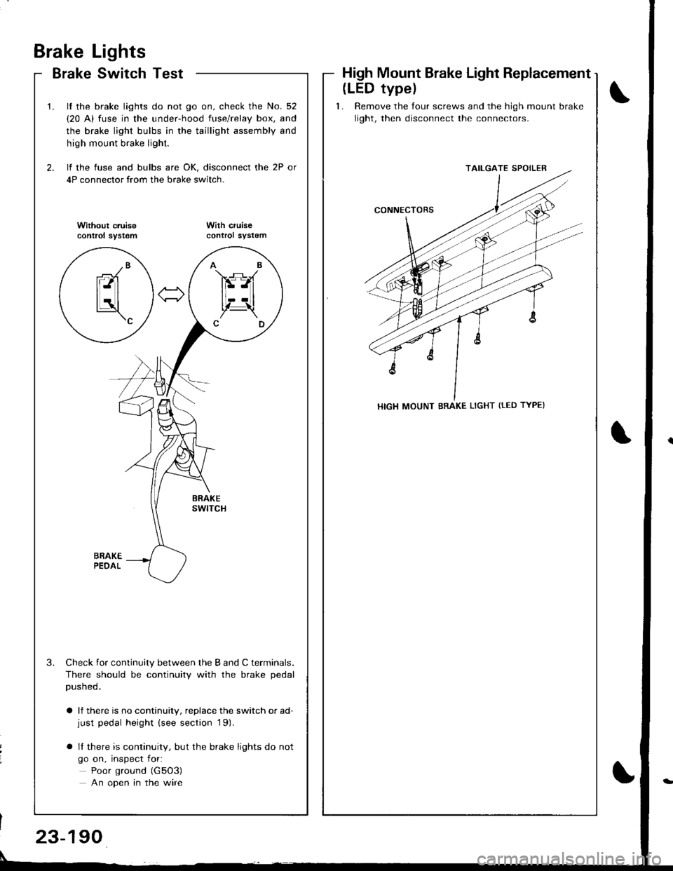
lf the brake lights do not go on. check the No. 52
{20 A) fuse in the under-hood fuse/relay box, and
the brake light bulbs in the taillight assembly and
high mount brake light.
lf the fuse and bulbs are OK, disconnect the 2P or
4P connector from the brake switch.
Without c.uisecontrol syst€mWilh cruisecontrol sYstem
Check for continuity between the B and C terminals.
There should be continuity with the brake pedal
pusneo.
a lf there is no continuity, replace the switch or ad-just pedal height (see section '19).
o It there is continuity, but the brake lights do not
go on, inspect for:
Poor ground (G5O3)
An open in the wire
AB
FS-A
lt--Ltl, t!,Z-\CD
-/Branl-ltl
tLatl\c
(LED typel
1. Remove the tour screws and the high mount brake
light, then disconnect the connectors.
TAILGATE SPOILER
HIGH MOUNT BRAKE LIGHT {tED TYPE}
23-190
Page 1317 of 1681
Gruise
- Brake
Control
Switch TestClutch Switch Test {M/T}
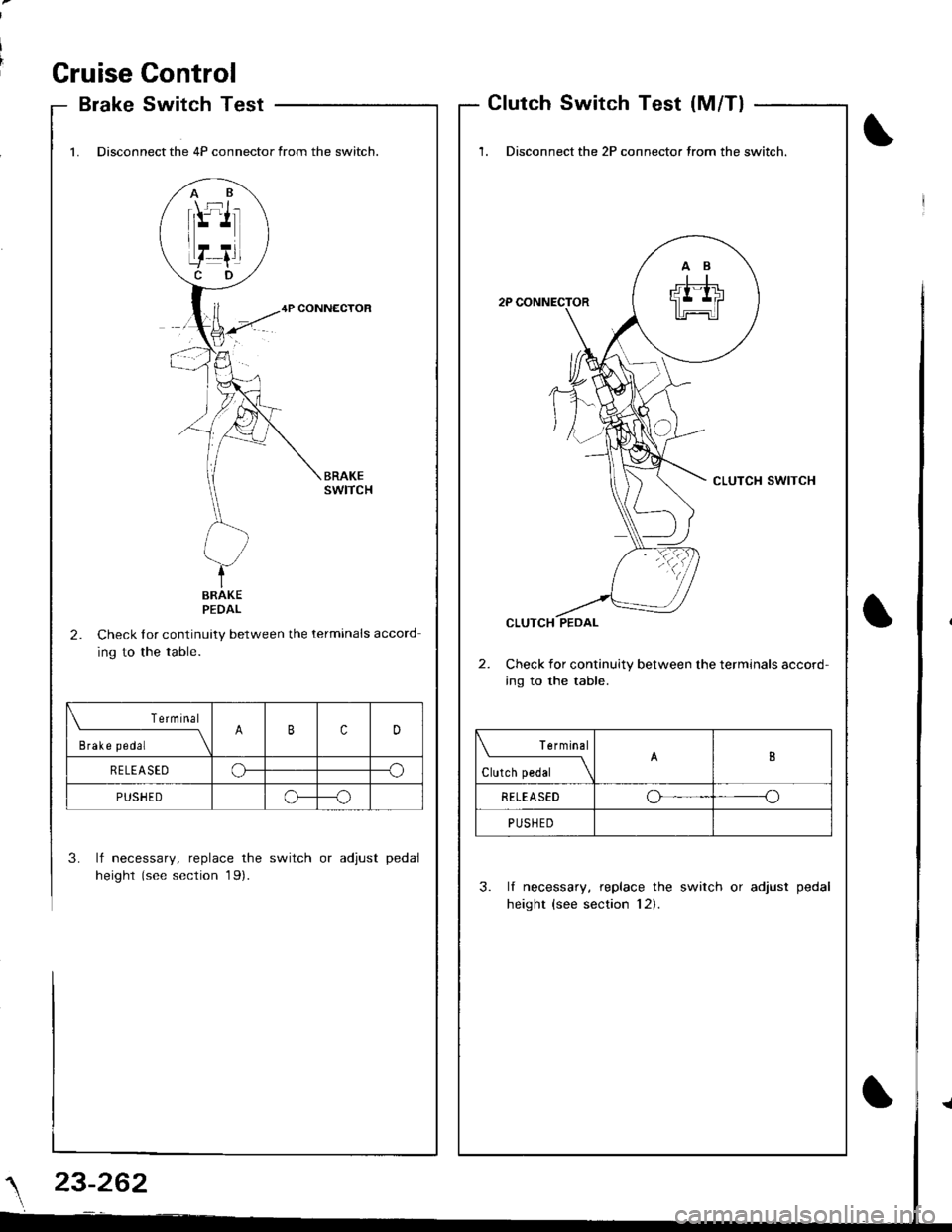
1. Disconnect the 4P connector from the switch.
4P CONNECTOR
2.Check lor continuity between the terminals accord
ing to the table.
3. lf necessary, replace the switch or adjust pedal
height (see section 19).
AB-\f:t-!l-'tr
I
f--! I
PEDAL
Terminal
;"r"*--__\BcD
R E LEA SEDCF--o
PUSH E Do---o
'1. Disconnect the 2P connector trom the switch.
2P CONNECTOR
CLUTCH SWITCH
CLUTCH PEDAL
Check for continuity between the terminals accord-
ing to the table.
3. lf necessary, replace the switch or adjust pedal
height (see section 12).
Terminal
.t"i*"1
I
RETEASEDoo
PUSHED
\
23-262
Page 1644 of 1681
I
I
Standards and Service Limits
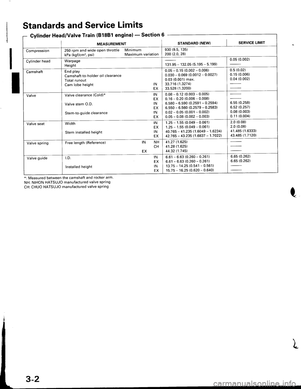
Cylinder Head/Valve Train (B18Bl engine)Section 6
*: Measured between the camshaft and rocker arm.
NH: NIHON HATSUJO manufactured valve spring
CH: CHUO HATSUJO manufactured valve spring
MEASUREMENTSTANDARD (NEW) I SERVICE LIMIT
Compression250 rpm and wide open throttle Minimum
kPa (kgf/cm'�, psi) Maximum variation930 (9.5, 135)200 Q.0,281
Cylinder headWarpageHeightta,|* - 132.05 (5.195 - 5.199)0.05 (0.002)
CamshaftEnd playCamshaft-to-holder oil clearanceTotal runoutCam lobe height lNEX
0.05 - 0.15 (0.002 - 0.006)0.030 - 0.069 (0.0012 - 0.0027)0.03 (0.001) max.33.7 16 11.327 4l33.528 ( 1.3200)
0.5 (0.02)
0.15 (0.006)
0.04 (0.002)
ValveValve clearance (Cold)" lNEX
Valve stem O.D. lNEX
Stem-to-guide clearance lNEX
0.08 - 0.12 (0.003 - 0.005)0.16 - 0.20 (0.006 - 0.00816.580 - 6.590 (0.2591 - 0.2594)6.550 - 6.560 (0.2579 - 0.2583)
0.02 - 0.05 (0.001 - 0.002)0.05 - 0.08 (0.002 - 0.003)
ouu to.rutt6.52 rc.2571.0.08 (0.003)
0.1 1 (0.004)
Valve seatwidth lNEX
stem installed height lNEX
1 .25 - 1.55 (0.049 - 0.061 )1.25 - 1 .55 (0.049 - 0.061 )40.765 - 41.235 (1.6049 - 1.6234142J65 - 43.235 (1.6837 - 1.70221
2.0 (0.08)
2.0 (0.08)
41.485 (1.6333)
43.485 (1.71201
Valve springFree length (Reference)IN NHCHEX
41.27 (1.6251
41.28 (1.625)
44.32 t1-7 451
Valve guidet.D. lNEX
Installed height lNEX
6.61 - 6.63 (0.260 - 0.261)6.61 - 6.63 (0.260 - 0.261)13.7 5 - 1 4.25 (0.541 - 0.561 )15.75 - 16.25 (0.620 - 0.640)
6.6s (0.262)
6.65 (0.262)
Page 1646 of 1681

Standards and Service Limits
8C1. 818C5 engines)Section 6Gylinder Head/Valve Train (B'lEC'1,
MEASUREMENTSTANDARD (NEW}SERVICE LIMIT
Compression250 rpm and wide open throttle Minimum
kPa (kgf/cm'�, psi) Maximum variation930 (9.5, 135)200 t2-0,281
Cylinder headWarpageHeightr** - 142.05 (5.589 - 5.593)0.05 (0.002)
CamshaftEnd playCamshaft-to-holder oi I clearanceTotal runoutCam lobe height lNPrimarY 818C1/818C5 engineMid 818C1/818C5 engineSecondarY 818C1/B18C5 engine
EXPrimarv 818C1/818C5 engineMid B18C1/818C5 engineSecondarv B1 8C1/818C5 engine
0.05 - 0.15 (0.002 - 0.006)
0.050 - 0.089 (0.0020 - 0.0035)0.03 (0.001) max.
33.41 1 (1.3154)/33.088 (1.3027)
36.377 (.43221/36.865 (1.4138)
34.547 (1.3601) 134.132 11-367 4l
33.1 1 1 ( 1.3036) 132.7 85 (1.29071
35.720 (1.4063)/36.333 (1.4304)
34.381 (1.3536)/34.691 (1.3658)
0.s (0.02)
0.15 (0.006)
0.04 (0.002)
ValveValve clearance (Cold)* lNEX
Valve stem O.D. lNEX
Stem-to-guide clearance lNEX
0.15 - 0.19 (0.006 - 0.007)0.17 - 0.2't (0.007 - 0.008)5.475 - 5.485 (0.2156 - 0.21595.450 - 5.460 (0.2146 - 0.2150
0.025 - 0.055 (0.0010 - 0.0022
0.050 - 0.080 (0.0020 - 0.0031
in* to.r',ool5.420 (0.2134)
0.08 (0.003)
0.1 1 (0.004)
Valve sealWidth lN 818C1 engineB18C5 engineEX B18C1 engine818C5 engine
Stem installed height lNEX
1.25 - 1.55 (0.049 - 0.061)
0.85 - 1.15 (0.033 - 0.045)1.25 - 1.55 (0.049 - 0.061)0.85 - 1.15 (0.033 - 0.045)37.465 - 37.935 (1.4750 - 1.4935)
37.165 - 37.635 (1.4632 - 1.48171
2.0 (0.08)
2.0 (0.08)
2.0 (0.08)
2.0 (0.08)
38.185 (1.5033)
37.885 (1.4915)
Valve springFree length (Referencel B18C1 engine:lN Outerlnner NHCHEX NHCH
818C5 engine:lN OuterlnnerEX Outerlnner
41.05 (1.616)
36.16 (1.424)
36.19 (1.425)
41 .96 (1.652)
41.94 (1.651)
43.19 (1.700)
36.84 (1 .450)41.05 (1.616)
36.16 (1.424)
Valve guidet.D. lNEX
Installed height lNEX
5"51 - 5.53 {'0.217 -0.2181
5.51 - 5.53 rc.217 - 0.218112.55 - 13.05 (0.494 - 0.5141
12.55 - 13.05 (0.494 - 0.514)
5.55 (0.219)
5.55 (0.219)
Rocker armArm-to-shaft clearance lNEX0.025 - 0.052 (0.0010 - 0.0020)0.025 - 0.052 (0.0010 - 0.0020)0.08 (0.003)
0.08 (0.003)
*: Measured between the camshaft and rocker arm
NH: NIHON HATSUJO manufactured valve spring
CH: CHUO HATSUJO manufactured valve spring
Page 1648 of 1681
Standards and Service Limits
missions - Section 11
* Including the pedal play 1 - 10 mm (0.04 - 0.39 in).
0Gooling - Sectlon
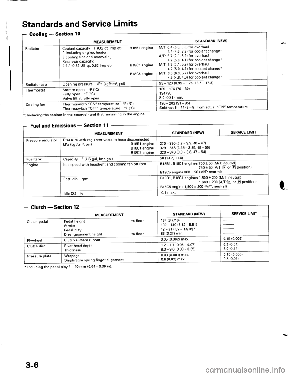
MEASUREMENTSTANDARD (NEW}
RadiatorCoolant capacity / (US qt, lmp qt) 81881 engine
I Including engine, heater, II cooling line and reservoir IReservoir capacity:0.6 f (0.63 US qt, 0.53 lmp qt) 818C1 engine
818C5 engine
M/T: 6.4 (6.8, 5.6) for overhaul4.4 14.6,3.9) for coolant change*
A,/T: 6.7 (7.1, 5.9) for overhaul4.7 $.0,4.1)for coolant change*
M/T: 6.7 (7.1,5.9) for overhaul4.7 (5.0, 4.1) for coolant change*
M/T: 6.5 (6.9, 5.7) for overhaul4.5 (4.8, 4.0) for coolant change*
Radiator capOpening pressure kPa (kgf/cm'�, Psi)93 - 123 (0.95 - 1.25, 13.5 - 17.8)
ThermostatStart to open 'F ("C)
Fully open "F ("C)
Valve lift at fully open
169 - 176 (76 - 80)194 (90)
8.0 (0.31)min.
Cooling fanThermoswitch "ON" temperature "F ('C)
Thermoswitch "OFF" temperature "F ("C)196 - 203 (91 - 95)Subtract 5 - 14 (3 - 8) from actual "ON" temperature
*: Including the coolant in the reservoir and that remaining in the engine
Fuel and E
MEASUREMENTSTANDARD (NEW}SERVICE LIMIT
Pressure regulatorPressure with regulator vacuum hose disconnected
kPa (kgf/cm'�, psi) 81881 engine818C1 engine818C5 engine
270 - 320 (2.8 - 3.3, 40 - 47].
329 - 378 (3.35 - 3.85, 48 - 55)
320 - 370 (3.3 - 3.8, 47 -541
Fuel tankCapacity / (US gal, lmp gal)50 (13.2, 11.0)
Engineldle speed with headlight and cooling fan off rpm81881, 818C1 engines 750 t 50 (M/T: neutral)750 I 50 (A/T: N or E Position)818C5 engine 800 t 50 (M/T: neutral)
Fast idle rpmB1881, 818C1 engines 1,600 t 200 (M/T: neutral)1,600 t 200 (A/T: E or E Position)818C5 engine 1,500 t 200 (M/T: neutral)
ldle CO %0.1 max.
Clutch - Section 'lZ
MEASUREMENTSTANDARD (NEW}SERVICE LIMIT
Clutch pedalPedal height to floor
StrokePedal playDisengagement height to floor
164 (6 7/16)130 - 140 (5.12 - 5.51)12 -21 (12 - 13/16)*83 (3.27) min.
FlywheelClutch surface runoul0.05 (0.002) max,0.15 (0.006)
Clutch discRivet head depthThickness
1.2 - 1.7 (0.05 - 0.07)8.3 - 9.0 (0.33 - 0.35)0.2 (0.01)
6.0 (0.24)
Pressu re plateWarpageDiaphragm spring finger alignmenl
0.03 (0.001) max.0.6 (0.021 max.
0.15 (0.006)
0.8 (0.03)
3-6
Page 1655 of 1681
MEASUREMENTSTANDARD (NEWI
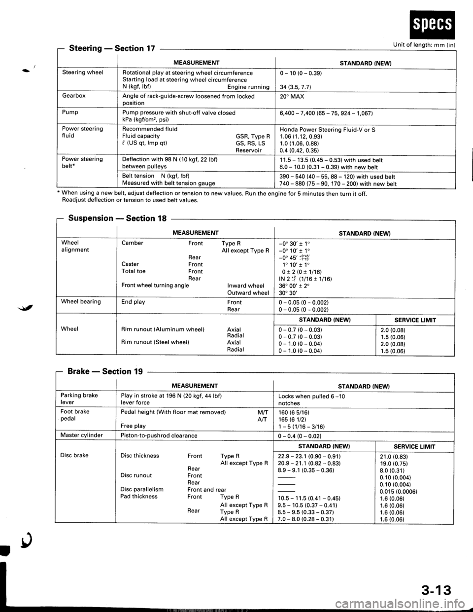
Steering wheelRotational play at steering wheel circumferenceStarting load at steering wheel circumferenceN (kgf, lbf) Engine running
0 - 10 (0 - 0.39)
34 (3.5,7 .71
GearboxAngle of rack-guide-screw loosened from lockedoosition20'MAX
PumpPump pressure with shut-off valve closedkPa (kgf/cm,, psi)6,400 - 7,400 (65 - 75, 924 - 1,067],
Power steeringfluidRecommended fluidFluid capacity GSR, Type Rf (US qt, lmp qtl cS, RS, LSReservoir
Honda Power Steering Fluid-V or S1.06 (1.12,0.93)
1.0 (1.06,0.88)
0.4 (0.42, 0.35)
Power steeringbelt*Deflection with 98 N (10 kgf,22 lbflbetween pulleys1 1.5 - 13.5 (0.45 - 0.531 with used belt8.0 - 10.0 (0.31 - 0.39) with new belt
Belt tension N (kgf, lbf)Measured with belt tension gauge390 - 540 (40 - 55, 88 - 120) with used belt740 - 880 (75 - 90, 170 - 2001with new belt
SteeringSection 17
* When using a new belt, adjust deflection or tension to new values. Run the engine for 5 minutes then turn it off.Readiust deflection or tension to used belt values.
Suspension - Section 18
BrakeSection 19
Unit of length: mm (in)
$t
MEASUREMENTSTANDARD (NEWI
WheelalignmentCamber Front Type RAll except Type RRearCaster FrontTotal toe FrontRearFront wheel turning angle Inward wheelOutward wheel
-0'30'r 1"-0' 10'r 1.-0" 45'�1?:i3i1. 10'�1 1.0!210!1116!,lN 2 lf (t7t6 1 1716136. 00'1 2"30'30'
Wheel bearingEnd play FrontRear0 - 0.05 (0 - 0.002)0 - 0.05 (0 - 0.002)
WheelRim runout (Aluminum wheel) AxialRadialRim runout (Steel wheel) AxialRadial
STANDARD (NEW}SERVICE LIMIT
0 - 0.7 (0 - 0.03)0 - 0.7 (0 - 0.03)0 - 1.0 (0 - 0.04)0 - 1.0 (0 - 0.04)
2.0 (0.08)
1.5 (0.06)2.0 (0.08)1.5 (0.06)
MEASUREMENTSTANDARD (NEW}
Parking brakeleverPlay in stroke at 196 N (20 kgf,44 lbf)lever forceLocks when oulled 6 -10
notches
Foot brakepedalPedal height (With floor mat removed)
Free play
M/TAtT160 (6 5/161165 rc 1nl1-5(1/16-3/16)
Master cylinderPiston-to-oushrod clearance0 - 0.4 (0 - 0.021
Disc brakeDisc thickness Front Type RAll except Type RRearDisc runout FrontRearDisc parallelism Front and rearPad thickness Front Type R
All except Type RRear Type RAll except Type R
STANDARD (NEWISERV]CE LIMIT
22.9 - 23.1 (0.90 - 0.91120.9 - 21.1 (0.82 - 0.83)
1= t (0.35-0.361
10.5 - 11.5 (0.41 - 0.45)9.5 - 10.5 (0.37 * 0.41)8.5 - 9.5 (0.33 - 0.37)7.0 - 8.0 (0.28 - 0.31)
21.0 (0.83)19.0 (0.75)
8.0 (0.31)
0.10 (0.004)
0.10 (0.004)
0.015 (0.0006)1.6 (0.06)
1.6 (0.06)1.6 (0.06)
1.6 (0.06)
Page 1657 of 1681
{b
Design Specifications
x1: At 6,000 engine rpm*2: At 7,600 engine rpm
0
(cont'd)
{
ITEMMETRICENGLISHNOTES
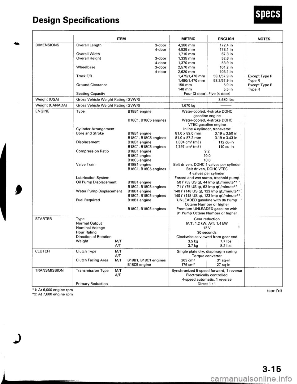
DIMENSIONSOverall Length 3-door4-doorOverall WidthOverall Height 3-door4-doorWheelbase 3-door4-doorTrack F/R
Ground Clearance
Seating Capacity
4,380 mm4,525 mm1,710 mm1,335 mm ]1,370 mm ]2,57O mm2,62O mm 11 ,415/1,470 mm I1,480/1,470 mm I1s0 mm I140 mm IFour (3-door),
172.4 in178.1 in67.3 in52.6 in53.9 in101.2 in103.1 in58.1/57.9 in58.3/57.9 in5.9 in5.5 tnFive (4-door)
Except Type RType RExcept Type RType R
weisht (usA)Gross Vehicle Weight Rating (GVWR)3.680 rbs
Weight (CANADA)Gross Vehicle Weight Rating (GVWR)1,670 kg
ENGINEType
Cylinder ArrangementBore and Stroke
Displacement
Compression Ratio
Valve Train
Lubrication SystemOil Pump Displacement
Water Pump Displacemenl
Fuel Required
8188l engine
818C1, Bl8C5 engines
81881 engine818C1, 818C5 engines81881 engine818C1, B18C5 engines81881 engine818C1 engine818C5 engineB1881 engine818C1, B18C5 engines
81881 engine818C1, B18CS enginesB1881 engine818C1, 818C5 enginesB1881 engine
818C1,818C5 engines
Water-cooled. 4-stroke DOHCgasoline engineWater-cooled, 4-stroke DOHCVTEC gasoline engineInline 4-cylinder, transverse81.0 x 89.0 mm | 3.19 x 3.50 in81.0 x 87.2 mm | 3.19 x 3.43 in1,834 cm3 (m/ ) | 112 cu-in1,797 cm3 (m/ ) | 110 cu-in9.210.010.6Belt driven, DOHC 4 valves per cylinderBelt driven, DOHC VTEC4 valves per cylinderForced and wet sump, trochoid pump50 f (53 US qt, 44 lmp qt)/minute*'71 ( (75 US qt,62 lmp qt)/minute*'� :
140 I 1148 US qt. 123 lmp qtl/minute*1140 t (148 US qt, 123 lmp qt)/minute*2UNLEADED gasoline with 86 PumpOctane Number or higherPremium UNLEADED gasoline with91 Pump Octane Number or higher
STARTERTypeNormal OutputNominal VoltageHour RatingDirection of RotationWeight MffAIT
Gear reductionMfi:1.2 kW, A,/T: 1.4 kW12V ,
30 secondsClockwise as viewed from gear end3.5 ks | 7.7 lbs3.7 kg | 8.2 lbs
CLUTCHClutch Type
Clutch Facing Area
M/TAfiM/T 81881, 818C1 engines818C5 engine
Single plate dry, diaphragm springTorque converter203 cm2 , 31 sq-in176 cm2 | 27 sq-in
TRANSMISSIONTransmission Type
Primary Reduction
M/TAITSynchronized S-speed forward, 1 reverseElectronical ly control led4-speed automatic, 1 reverseDirect 1 : 1
3-15