1998 HONDA INTEGRA ground
[x] Cancel search: groundPage 1284 of 1681
)
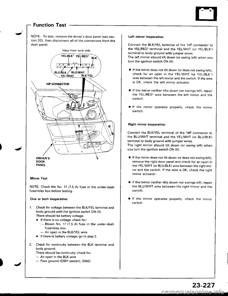
Function Test
NOTE: To test, remove the driver's door panel (see sec-
tion 20), then disconnect all of the connectors from the
ooor panet.
Mifior Test
NOTE: Check the No. 17 {7.5 A) fuse in the under-dashfuse/relay box before testing.
One or both inoperative:
Check for voltage between the BLK//EL terminal and
body ground with the ignition switch ON {ll).There should be battery voltage.
. lf there is no voltage, check for:* Blown No. 17 (7.5 A) fuse in the under-dash
fuse/relay box- An open in the BLK/YEL wire
. lf there is battery voltage, go to step 2.
Check for continuity between the BLK terminal and
body ground.
There should be continuity; check for.* An open in the BLK wire- Poor ground (G501 (sedan), G502)
vrllBtxt YEL/RED' aa*\
Left miror inoperative:
Connect the BLK,^/EL terminal of the 1OP connector to
the YEVRED1terminal and the YEL /VHT (or YEL/BLK1)
terminal to body ground with iumper wires.
The left mirror should tilt down (or swing left) when you
turn the ignition switch ON (ll).
a lf the mirror does not tilt down (or does not swing lett).check for an open in the YEL/WHT {or YEL/BLKr}wire between the left mirror and the switch. lf the wireis OK, check the lett mirror actuaror.
a lf the mirror neither tilts down nor swings left, repair
the YEL/REDr wire between the letr mirror and theswtlcn.
a lf the mirror operates properly, check the mirror
swttcn.
Right mirrol inoperative:
Connect the BLK/YEL terminal of the 10P connector to
the BLU,^/VHT terminal and the YELMHT {or BLU/BLK)
terminal to body ground with jumper wires.
The right mirror should tilt down (or swing left) whenyou turn the ignition switch ON (ll).
a lf the mirror does not tilt down (or does not swing left),
remove the right door panel and check for an open in
the YEL/WHT (or BLU/BLK) wire between the right mir-
ror and the switch. lf the wire is OK, check the right
mirror actuator.
a lf the mirror neither tilts down nor swings lett, repair
the BLU/WHT wire between the right mirror and the
swrtch.
a lf the mirror operates properly, check the mirror
switch.
23-227
Page 1290 of 1681
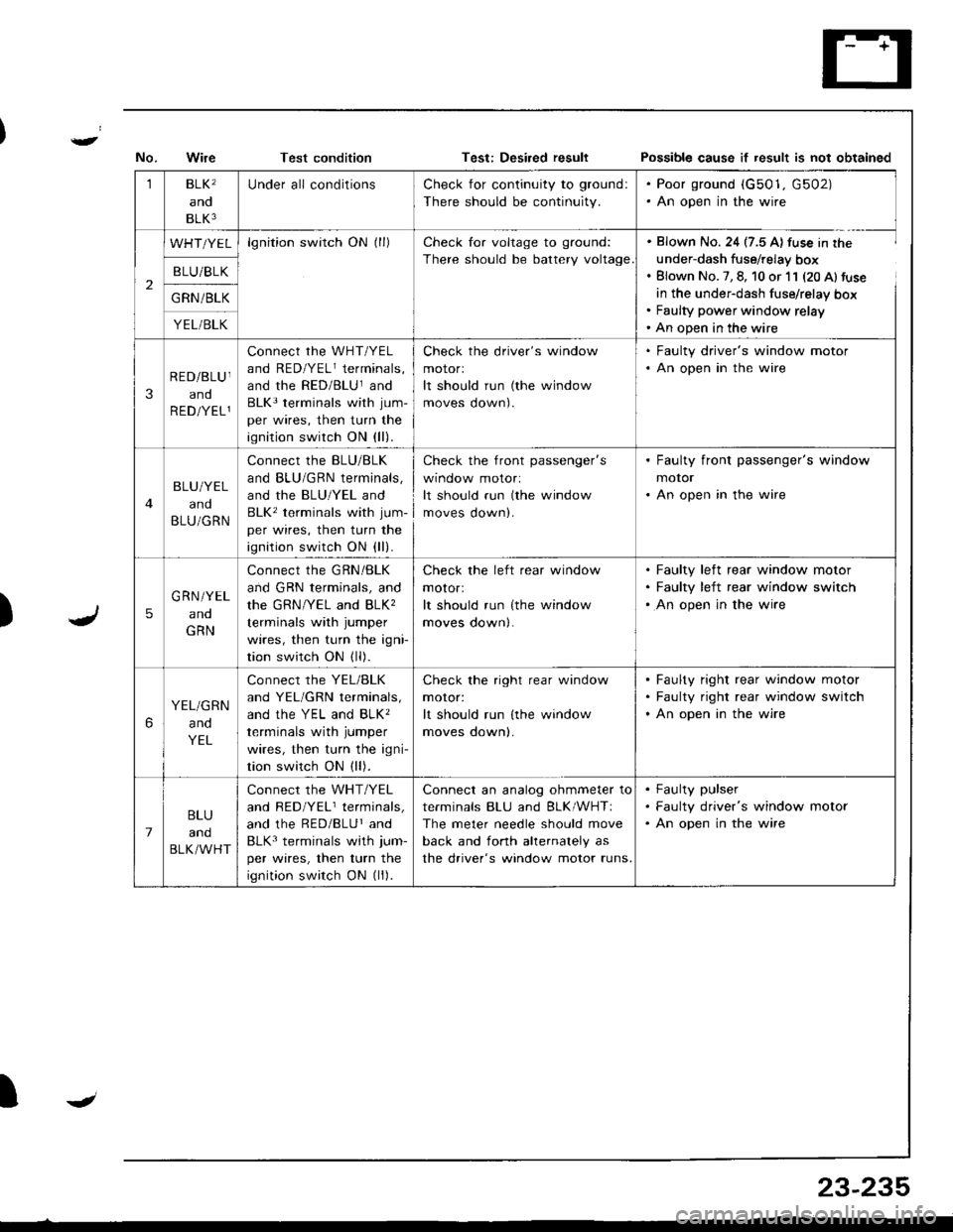
Test conditionPo$sible cause if result is not obtained
)
1BLK'
and
BLK3
Under all conditionsCheck for continuity to ground:
There should be continuity.
. Poor ground (G501, G502). An open in the wire
2
WHT/YELlgnition switch ON (ll)Check for voltage to ground:
There should be battery voltage
. Blown No. 24 (7.5 A) fuse in the
under-dash fuse/relay box. Blown No. 7, 8, 10 or 11 (20 Al fuse
in the under-dash fuse/relay box. Faulty power window relay' An open in the wire
B LU/BLK
G RN /BLK
YEL/BLK
3
RED/BLU I
and
R ED/YEL1
connect rhe wHT/YEL
and RED/YELr terminals,
and the RED/BLUland
BLK3 terminals with jum-
per wires, then turn the
ignition switch ON (ll).
Check the driver's window
motorl
It should run (the window
moves oown).
. Faulty driver's window motor. An open in the wire
BLU/YEL
and
BLU/GRN
Connect the BLU/BLK
and BLU/GRN terminals,
and the BLU/YEL and
BLK' terminals with jum-
per wires, then turn the
ignition switch ON (ll).
check the front passenger's
wtnoow molor:
It should run (the window
moves down).
. Faulty front passenger's window
motor. An open in the wire
5
G RN/YEL
ano
GRN
Connect the GRN/BLK
and GRN terminals, and
the GRN/YEL and BLK,
terminals with jumper
wires, then turn the igni
tion switch ON (ll).
Check the left rear window
motor:
It should run {the window
moves down|.
Faulty left rear window motor
Faulty left rear window switch
An open in the wire
6
YEL/GRN
and
YEL
Connect the YEL/BLK
and YEL/GRN terminals,
ANd thc YEL ANd BLK'
terminals with jumper
wires, then turn the igni-
tion switch ON (ll).
Check the right rear window
moror:
It should run lthe window
moves oownl.
Faulty right rear window motor
Faulty right rear window switch
An open in the wire
7
BLU
and
BLK/WHT
Connect the WHT/YEL
and RED/YELr terminals,
and the RED/BLUr and
BLK3 terminals with jum-
per wires, then turn the
ignition switch ON (ll).
Connect an analog ohmmeter to
terminals BLU and BLK/WHTI
The meter needle should move
back and fonh ahernalely as
the driver's window motor runs.
Faulty pulser
Faulty driver's window motor
An open in the wire
IJ
23-235
Page 1291 of 1681
Power
Master
Windows
Switch Input Test (Hatchbackl
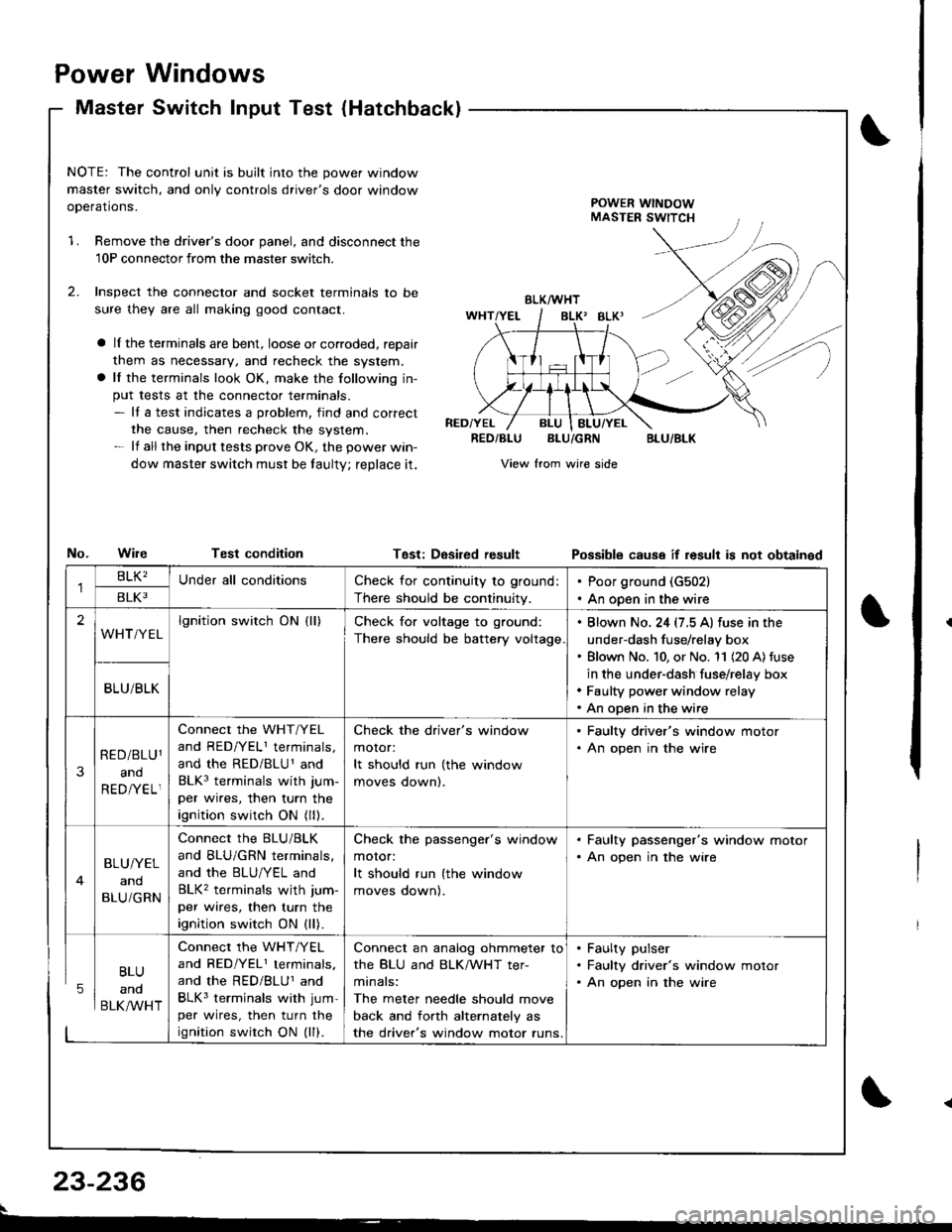
NOTE: The control unit is built into the power window
master switch, and only controls driver's door window
ooerations.POWER WINDOWMASTER SWITCH
1.Remove the driver's door panel, and disconnect the
10P connectorfrom the master switcn.
Inspect the connector and socket terminals to be
sure they are all making good contact.
a lI the terminals are bent, loose or corroded, reDair
them as necessary, and recheck the system.
a lf the terminals look OK, make the following in-
put tests at the connector terminals.- It a test indicates a problem, find and correct
the cause, then recheck the system.- lf all the input tests prove OK, the power win-
dow master switch must be taulty; reDlace it.
No.WileTest condition
BLK/WHT
BLK' BLKI
RED/YELRED/BLUBLU/GRNBLU/BLK
View from wire side
Tgst: DesiredresultPossibls cause if result is not obtainsd
BLU
and
BLK/WHT
Check for continuity to ground:
There should be continuity.
Poor ground (G502)
An open in the wire
lgnition switch ON (ll)Check for voltage to ground:
There should be battery voltage
. Blown No. 24 (7.5 A) fuse in the
under-dash fuse/relay box' Blown No. 10, or No. '11 (20 A) fuse
in the under-dash fuse/relay box. Faulty power window relay. An open in the wire
Connect the WHT/YEL
and RED/YELI terminals,
and the RED/BLU1 and
BLK3 terminals with jum-
per wires, then turn the
ignition switch ON (ll).
Check the driver's window
motor:
It should run (the window
moves oownl.
. Faulty driver's window motor. An open in the wire
Connect the BLU/BLK
and BLU/GRN terminals,
and the BLU/YEL and
BLK2 terminals wjth jum-
per wires, then turn the
ignition switch ON (ll).
Check the passenger's window
motor:
It should run (the window
moves oownl.
. Faulty passenger's window motor. An open jn the wire
Connect the WHT/YEL
and RED/YEL1 terminals.
and the RED/BLUI and
BLK3 terminals with jum-
per wires, then turn the
ignition swirch ON (ll).
Connect an analog ohmmeter to
the BLU and BLK/WHT ter-
minals:
The meter needle should move
back and forth alternately as
the driver's window motor runs.
. Faulty pulser. Faulty driver's window motor. An open in the wire
23-236
Page 1295 of 1681
Power Windows
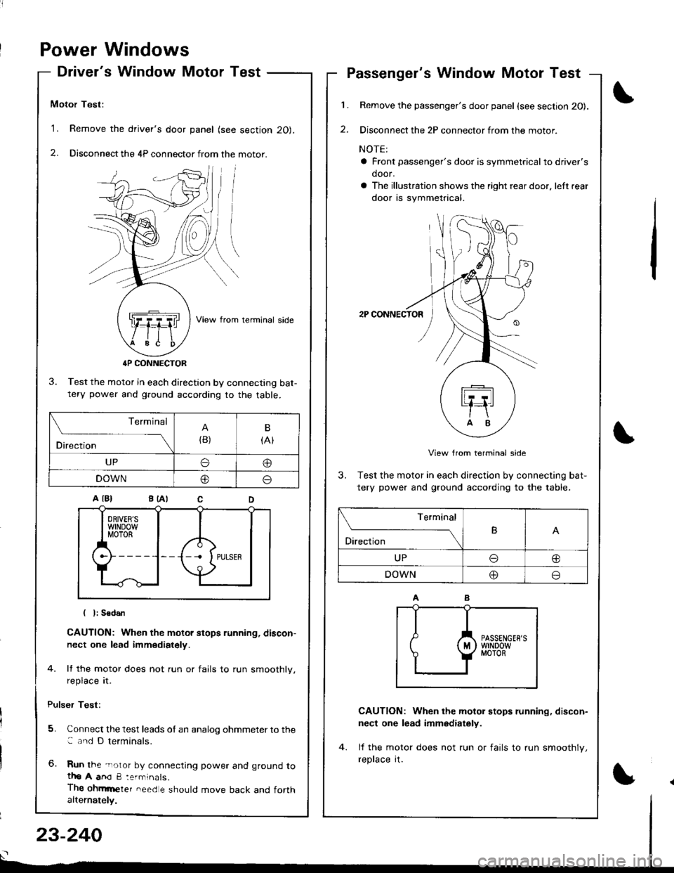
Driver's Window Motor Test
Motor Test:
'1. Remove the driver's door panel (see section 20).
2. Disconnect the 4P connector from the motor.
View from terminal side
4P CONNECTOR
3. Test the motor in each direction by connecting bat-tery power and g.ound according to the table.
CAUTION: When the motor stops running, discon-
nect one lead immediately.
4. lf the motor does not run or fails to run smoothly.
reprace rI.
Pulser Test:
5. Connect the test leads of an analog ohmmeter to the: and D terminals.
6. Run the -noror by connecting power and ground totho A anO 8:errninals.
Thg ohmrneter need e should move back and forthalternately,
1.
2.
Passenger's Window Motor Test
Remove the passenger's door panel {see section 20).
Disconnect the 2P connector from the motor.
NOTE:
a Front passenger's door is symmetricalto driver's
door.
a The illustration shows the right rear door. left rear
door is symmetrical.
2P CONNECTOR
View from terminal side
3. Test the motor in each direction by connecting bat-
tery power and ground according to the table.
CAUTION: When the motol stops running, discon-
nect one lead immediately.
lf the motor does not run or fails to run smoothlv,
reprace rI.
(
I
Terminal
Direction{B)
B
{At
UPo@
DOWN@o
Terminal
O'*"r*-TB
UPo@
DOWN@o
23-240
Page 1300 of 1681
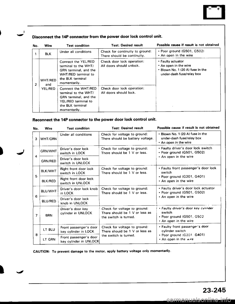
Disconnect the 14P connector from the power door lock control unit'
)
No. WileTest conditionTest: Dgsired resultPossible causo if rosult is not obtained
Reconnect the 14P conneetor to the power door lock control unit'
No. wireTest conditionTest: Desired resultPossible cause il result is not obtained
I
1BLKUnder all conditionsCheck tor continuity to ground:
There should be continuity.
. Poor ground (G50'1, G502). An open in the wire
2
WHTi RED
ano
YEL/RED
connect the YEL/RED
terminal to the WHT/
GBN terminal, and the
WHT/RED terminal to
the BLK terminal
momentarily.
Check door lock operation:
All doors should unlock.
Faulty actuator
An open in the wire
Blown No. 1 {20 A} fuse in the
under-dash Juse/relay box
Connect the WHT/RED
terminal to the WHT/
GRN terminal, and the
YEL/RED terminal to
the BLK terminal
momentanly.
Check door lock operation:
All doors should lock.
3WHT/GRN
Under all conditionsCheck for voltage to ground:
There should be battery voltage.
. Blown No. 1 (20 A) fuse in the
under-dash fuse/relay box. An open in the wire
GRN/WHTDriver's door lock
switch in LOCK
Check lor voltage to ground:
There should be 1 V or less.
Faulty driver's door lock switch
Poor ground (G501, G502)
An open in the wire
GRN/REDDriver's door lock
switch in UNLOCK
5
BLK/WHTRight front door lock
switch in LOCK
Check for voltage to ground:
There should be 1 V or less.
Faulty front passenger's door lock
switch
Poor ground (G201 , G401)
An open in the wireBLKi REDRight front door lock
switch in UNLOCK
BLU/WHTDriver's door lock knob
in LOCK
Check for voltage to ground:
There should be 1 V or less.
. Faulty driver's door lock actuator. Poor ground (G501, G502). An open in the wire
BLU/REDDriver's door lock
knob in UNLOCK
7BRN
Oriver's doo. key
cylinder in UNLOCK
Check for voltage to ground:
There should be 1 V or less as
the switch is turned.
. Faulty driver's door key cvtrrder
switch. Poor ground (G501, G502. An open in the wire
8
LT BLUFront passenger's door
key cylinder in LOCK
Check for voltage to ground:
There should be 1 V or less as
the switch is turned.
. Faulty front passengef's door
cylinder switch. poor ground lG20r G4Ol). An open in the *reLT GRNFront passenger's door
key cylinder in UNLOCK
\J
CAUTION: To prevent damage to the motol, apply battery voltage only momentarily
23-245
Page 1301 of 1681
r
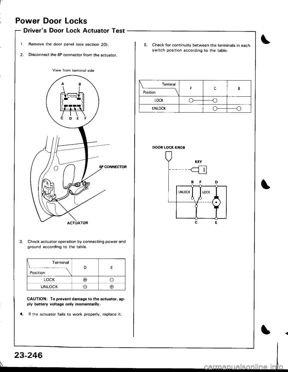
Power Door Locks
Driver's Door Lock Actuator Test
Remove the door panel (see section 20).
Disconnect the 6P connector from the actuator.
CONNECTOR
Check actuator operation by connecting power and
ground according to the table.
CAUTION: To prevent damage to the acluator, ap-ply battely voltage only momentarily.
if the actuator fails to work properly, replace it.
Terminal
DE
Position
LOCK@o
UNLOCKo@
5. Check for continuity between the terminals in each
switch position accordiog to the table.
DOOR LOCK KNOB
Terminal
il;;-----tFcB
LOCKoo
UNLOCKo-----o
23-246
Page 1302 of 1681
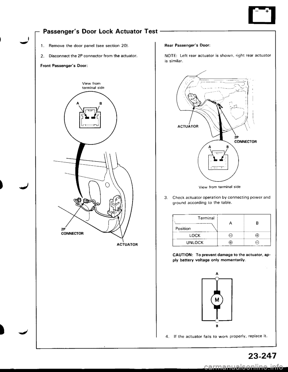
Passenger's Door Lock Actuator Test
1. Remove the door panel (see section 20).
2. Disconnect the 2P connector from the actuator.
Front Passenger's Door:
lerminal side
ACTUATOR
)J
23-247
Rear Passenger's Door:
NOTE: Left rear actuator is shown, right rear actuator
is similar.
View from lerminal side
Check actuator operation by connecting power and
ground according to the table.
CAUTION: To prevent damage to the actuator, ap-
ply battery voltage only momenta.ily.
;
4. lf the actuator tails to work properly, replace it.
Term inal
Position
B
LOCKo@
UNLOCKoo
Page 1305 of 1681
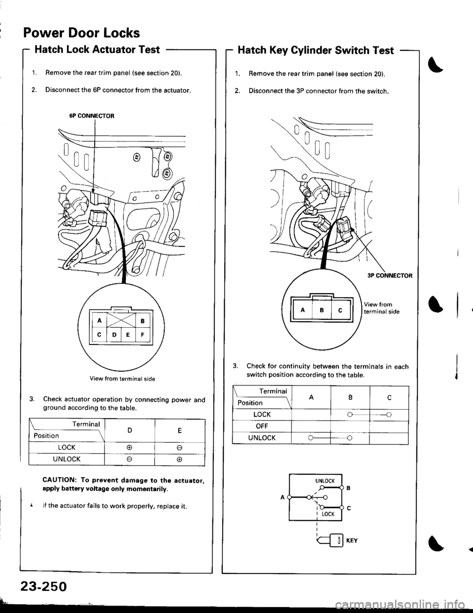
Power Door Locks
Hatch Lock Actuator Test
Remove the rear t.im panel (see section 20).
Disconnect the 6P connector from the actuator.
1.1.
2.
Hatch Key Cylinder Switch Test
Remove the rear trim panel (see section 20).
Disconnect the 3P connector from the switch.
3. Check for continuitv between the terminals in each
switch position according to the table.
6P CONNECTOR
3. Check actuator operation by connecting power andground according to the table.
CAUTION: To prev€nt damage to the actuator,
apply battery voltage only momeniarily.
1 lf the actuator fails to work properly, replace it,
23-250
Terminal
ilil;---tBc
LOCKoo
UNLOCKo
Terminal
ilil;-]E
LOCK@o
UNLOCKoo
UNLOCK
.-,4
I LOCK
| !J KEY