1998 HONDA INTEGRA ground
[x] Cancel search: groundPage 1368 of 1681
Troubleshooting
DTC 2-'l (cont'd)
From pago 23-313
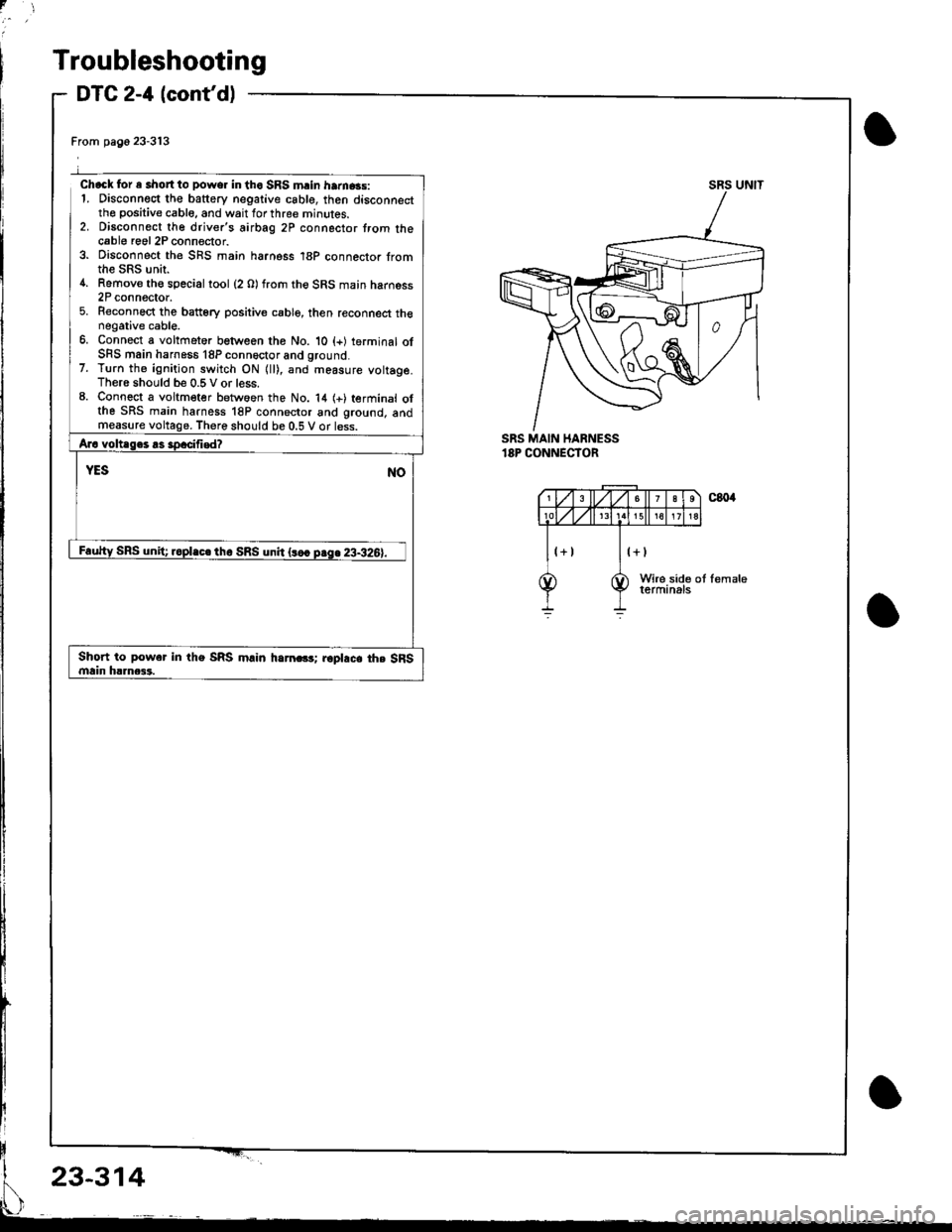
Chack for e short to power in tho SRS mrin ham.3s:1. Disconnect the battery negative csble, then disconnectthe positive cable, and wait for three minutes.2. Disconnect the driver's airbag 2P connector trom thecable roel 2P connector.3. Disconnect the SnS main harness 18P connector fromthe SRS unir.4. Remove th€ special tool (2 O) from the SRS main harness2P connector.5. Reconnect the batt6ry positive cable, then reconnect thenegative cable.6. Connect a voltfieter between the No. 10 (+) terminal ofSFS main harness 18P conn6ctor and ground.7. Turn th6 ignition switch ON {ll), and measure vottage.There should be 0.5 V or less.8. Connect a voltmeter betwoen the No. 14 (+) terminal olthe SRS main harness 18P connector and ground, andmeasurethere should be 0.5 V or less.
SRS UNIT
SRS MAIN HARNESS'8P CONNECTOR
Short to power in the SRS m.in harn.G; r6pl.c. th. SFSmain h!]nca3.
23-314
Page 1369 of 1681
DTC 2-5
CAUTION: Whenever the ignition switch is ON (lll. ot
has been turned OFF lor less than thlee minules. be
careful not to bump the SRS unit; th€ airbags could
accidentally deploy and cause damage 01 injuri€s.
lnta.mittor tailure, aFtcrn b OK st ihb ti.rF. Sa. Tto.tbl''_
Intermittont FriluJor on pag€ 2&289.
SRS MAIN HARNESA2P CONNECTORml tlssfrliaFs AnSaG
)
u---
or
SRS SERVICECoNNECTOR {2 0lo?TM - 5250200
(cont'd)
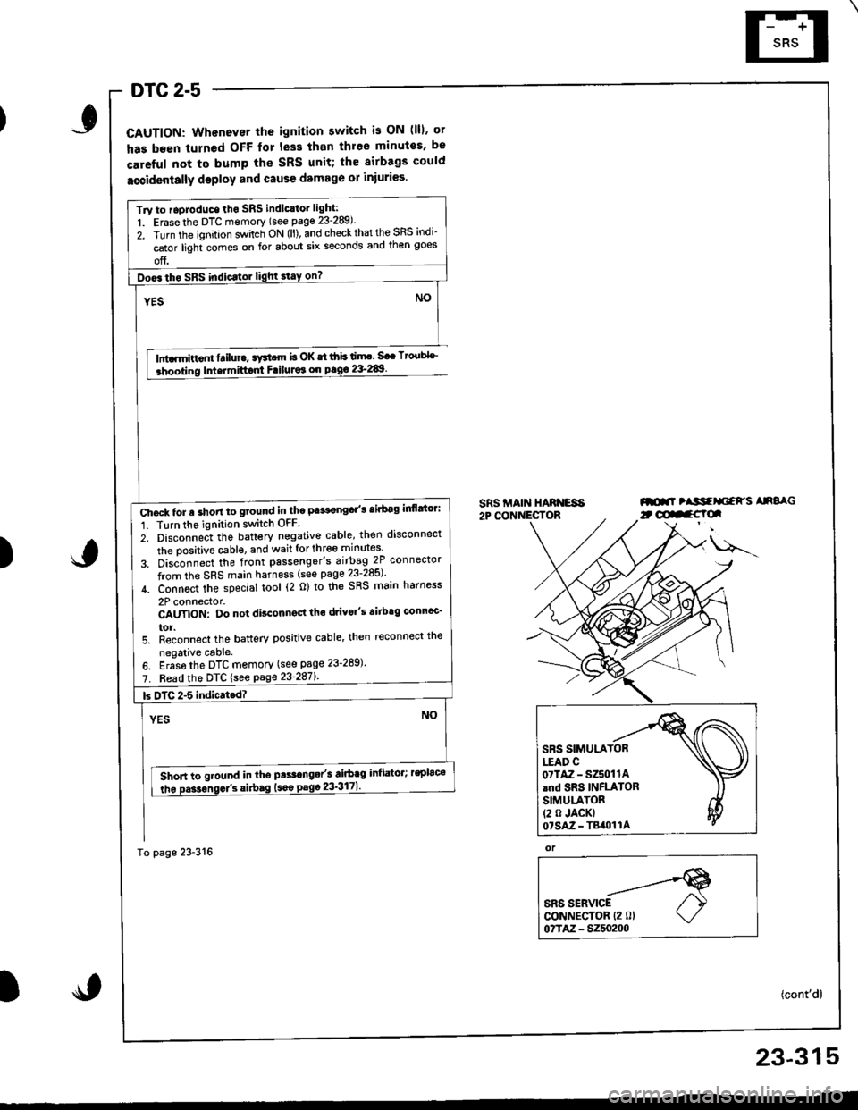
Try to roproduce tho SRS indic.tor light:
1. Erase the DTC memory (see page 23-289).
2. Turn the ignition sv/itch ON (ll). and check that the SRS indi-
cator light comes on for about six seconds and then goes
off.
Doo6 tho SRS indic.tor light stay on?
Chgck tor a short to ground in the Pa*t€ngd'3 tirbag inflttor:
1. Tlrn the ignition switch OFF
2. Disconnect the battery negative cable, then disconnect
the oositive cable. and wait for thr€6 minutes
3. Dis;onnect the front passenger's airbag 2P connector
from the SRS main harness (see page 23-285)'
4. Connoct the special tool (2 o) to the SRS main harness
2P connector.CAUTION: Do not disconngd tho drivo"s airbtg connoc'
tor.5. Reconnect the battery positive cable' then reconnect the
negalive cable.
6. Eras6 the DTC memory (see page 23-289)'
7. Fead the DTC {see page 23'287l'.
Short to ground in tho pts.range/s airbag inflator; rsplac€
tho Da3sonse/3 si.bag (sao
23-315
Page 1370 of 1681
Troubleshooting
DTC 2-5 lcont'd)
From p3g€ 23-315
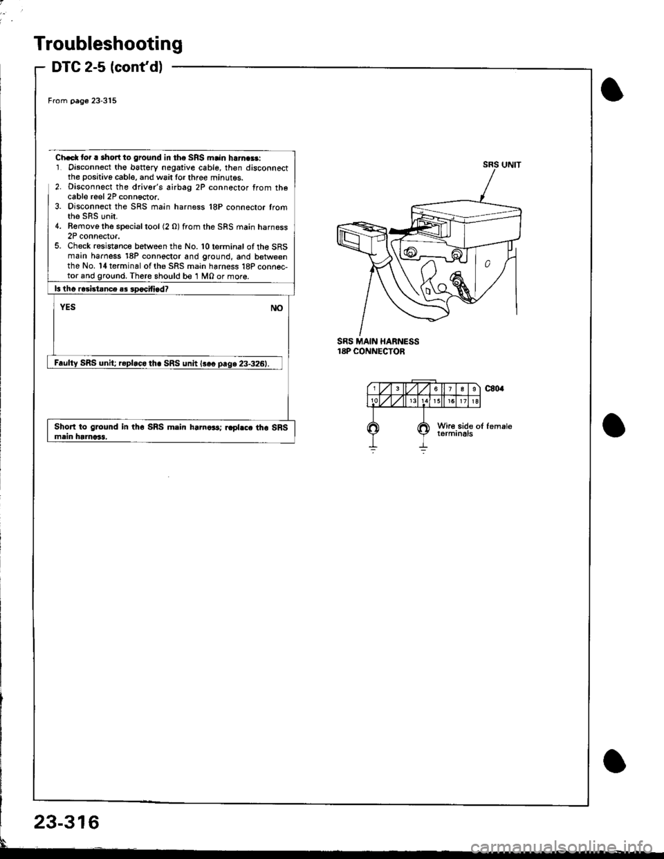
Ch.d( tor r short to ground in the SRS main harne$:1. Oisconnect th€ b6ttery negative cable, then disconnectthe positive cable, and wait lor three minutos.2. Disconngct the driver's airbag 2P connector from thecable reel 2P conn6ctor.3. Disconnect the SRS main harness 18P connector tromthe sRs unir.4. Bemove the special tool (2 0) from the SRS main harness2P connector.5. Check resistsnce between the No.'l0terminal oftheSRSmain harness 18P connector and ground, and betweenthe No. l4 terminal of the SRS main harness 18P connec-There should be '1 M0 or mor€.
SRS MAIN HARNESS18P CONNECTOR
SRS unit; r.pbco th. SRS unh lsoo
Short to glound in th6 SRS mein hamo33; rapl.c. tho SRSmain ht]noSl,
23-316
Page 1375 of 1681
)6.
7.
8.
Connect a 12 volt battery to the tool:
. lf the green light on the tool comes on, the alr-
bag igniter circuit is defective and cannot deploy
the airbag. Go to Damaged Airbag Specia I
Procedure.
. lfthe red light on the tool comes on, the airbag is
ready to be deployed.
Push the tool's deployment switch The airbag
should deploy (deployment is both highly audible
and visible; a loud noise and rapid inflation of the
bag, followed by slow deflation).
. lf the airbags deploy and the green light on the
tool comes on, continue with this procedure
. lf an airbag doesn't deploy. yet the green light
comes ON, its igniter is defective. Go to Dam-
aged Airbag Special Procedure.
!!@ During deployment, the airbag c8n
become hot enough to burn you Wait thirtY min-
ut€s after d€ployment befote touching the assem-
blv.
Dispose of the complete airbag. No part of it can be
reused. Place it in a sturdy plastic bag, and seal it
securery.
CAUTION:
. wear a lace shield and gloves when handling a
deployed airbag.
. Wash your hands and rinse them well with
water after handling a deployed sirbag
)
Deploying the Airbag: Out-ot-vehicle
NOTE: lf an intact airbag has been removed from a
scraDDed vehicle, or has been found defective or dam-
aged during transit, storage or service, it should be
deoloved as follows:
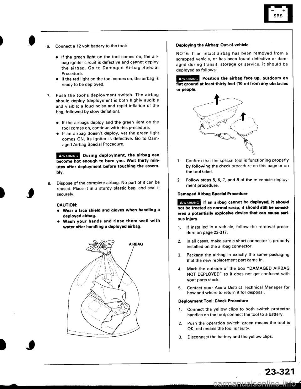
@@ Position th€ airbag laca up. outdoors on
tlat ground at l€ast thirty leet (10 m) ftom any obstacles
or people.
1. Confirm that the special tool is functioning properly
by tollowing the check procedure on thls page or on
the tool lab€|.
2. Follow steps 5, 6, 7, and 8 ol the in.vehicle deploy'
ment orocedure.
Damaged Airbag Sp€citl Procedurc
!@ [ an airbag cannot be d.ploytd, h 3hoold
not be lreated as normal scrap; it should 3till b. corlrkl
ered a polentially sxplosive device that can clura tari
ous iniury.
1. lf installed in a vehicle, follow the removal proce-
dure on page 23-317.
2. ln all cases, make sure a short connector is properly
installed on the airbag connector.
3. Package the airbag in exactly the same packaging
that the new replacement part came In.
4. Mark the outside of the box "DAMAGED AIRBAG
NOT DEPLOYED" so it does not get confused with
your Parts stock.
5. Contact your Acura District Technical lvanager for
how and where to return it for disposal.
Deployment Tool: Ch€ck Ptocedure
1. Connect the yellow clips to both switch protector
handles on the tool; connect the tool to a battery
2. Push the operation switch: green means the tool is
OK; red means the tool is faultv.
3. Disconnect the battery and the yellow clips
23-321
Page 1383 of 1681
).1
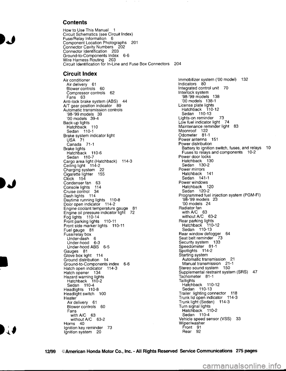
Contents
How to Use This l\.4anual 1Circuit Schematics (see Circuit Index)Fuse/Relaylnformation 6ComponentLocation Photographs 201
Connector Cavity Numbers 202Connectorldentification 203
Ground-to-Components Index 6-6Wire Harness Routing 203Circuit ldentification lor ln-Line and Fuse Box Connectors
Circuit Index
Air conditionerAir delivery 61Blower controls 60Compressor controls 62Fans 63Anti-lock brake system (ABS) 44A/T gear position indicator 89Automatic transmission controls'98199 models 39'00 models 39-4Back-up lightsHatchback 110Sedan 110- 1Brake system indicator light
USA 71Canada 71-1Brake lightsHatchback 110-6Sedan 110-7Cargo area light (Hatchback) 114-3Ceiling light 114-2Charging system 22Cigarette lighter 155
Clock 154Condenser fan 63Console lights 114Cruise control 34Dash lights 1 14Daytime running lights 110-8Door open indicator 114-2Engine coolant temperature gauge 81Engine oil pressure indicator light 72Fog lights 110-14Front parking lights 110-11Front side marker lights 110-11Fuel gauge 81Fuse/relay boxUnder-dash 6Under-hood 6-3Under-hood ABS 6-5Gauges 81Glove box light 114Ground distribution 14Ground-to-Componentsindex 6-6Hatch open indicator '114-3
Hatch opener '134
Hazard warning lightsHatchback 'l l0-2Sedan 110-4Headlights 1'10-8Headlight switch 100HeaterAir delivery 61Blower controls 60Fanswith A,/C 63without A,/C 63-2Horns 40lgnilion key reminder 73lgnition system 20
204
lmmobilizer system ('00 model) 132lndicators 80Integrated control unit 70Interlock system'98199 models 138'00 models 138-1License plate lightsHatchback 110-12Sedan 110-13Lights-on reminder 73Low fuel indicator light 74l\,4aintenance reminder light 83l\iloonroof 122Odometer 81-1Power antenna 151Power distributionBattery to ignilion switch, fuses, and relays
Fuses to relays and components 10-2Power door locksHatchback '130
Sedan 130-2Power mirrorsHatchback 141Sedan 141-1Power windowsHatchback 120Sedan 120-2Programmed fuel injection system (PGM-Fl)'98199 models 23'00 models 24Radiator fanwith tuC 63without A,/C 63-2Rear parking lightsHatchback 110-12Sedan 110- 13Rear window defogger 64Seat belt reminder 73Security system 133Speedometer Il-1Spotlights 114-2Starting syslemAutomalictransmission 21l\.4anualtransmission 21-1Stereo sound system 150Supplemental restraint system (SRS) 47Tachometer 81- 1TaillightsHatchback 110-12Sedan 110-13Trailer lighting conneclor 118Trunk lid open indicator 114-3Trunk light (Sedan) 114-3Turn signal lightsHatchback 110-2Sedan 110-4Vehicle speed sensor (VSS) 33Wiper/washerFront 91Rear 92
10
).1
I
Xr
12Fg oAmerican Honda Motor Co., Inc. - All Rights Reserved Service Communications 275 pages
Page 1385 of 1681
How To Use This Manual
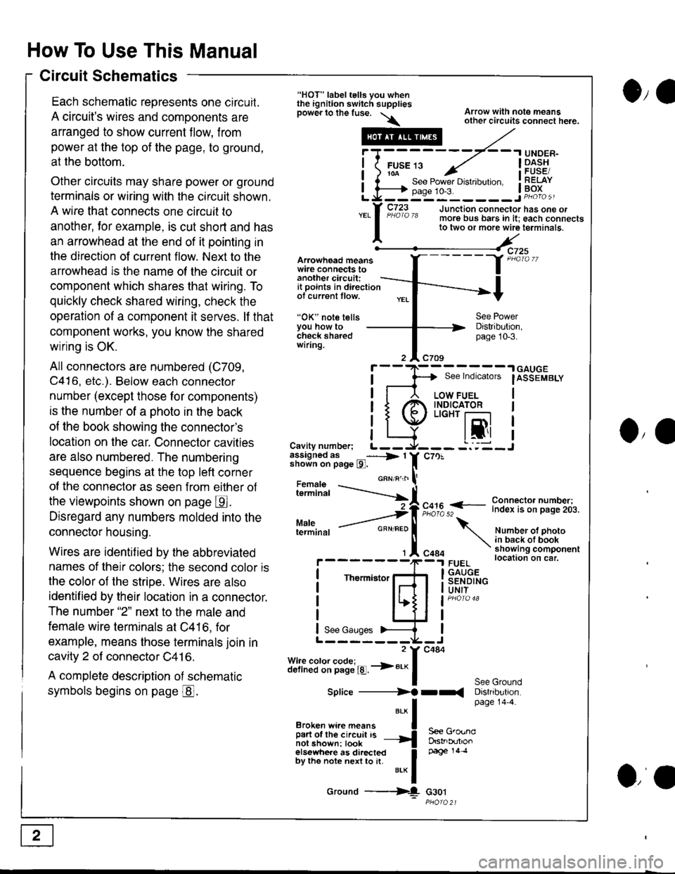
Circuit Schematics
Each schematic reoresents one circuit.
A circuit's wires and components are
arranged to show current flow, from
power at the top of the page, to ground,
at the bottom.
Other circuits may share power or ground
terminals or wiring with the circuit shown.
A wire that connects one circuit to
another, lor example, is cut short and has
an arrowhead at the end of it pointing in
the direction of current flow. Next to the
arrowhead is the name ol the circuit or
component which shares that wiring. To
quickly check shared wiring, check the
operation of a component it serves. lf that
component works, you know the shared
wiring is OK.
All connectors are numbered (C709,
C416, etc.). Below each connector
number (except those for components)
is the number of a ohoto in the back
of the book showing the connector's
location on the car. Connector cavities
are also numbered. The numbering
sequence begins at the top left corner
of the connector as seen from eilher of
the viewpoints shown on page E.
Disregard any numbers molded into the
connector housing.
Wires are identif ied by the abbreviated
names of their colors; the second color is
the color of the stripe. Wires are also
identif ied by their location in a connector.
The number "2" next to the male and
female wire terminals at C416, for
example, means those terminals join in
cavity 2 of connector C41 6.
A complete description of schematic
symbols begins on page @.
O,e
Arowhead meanswire connects toanother ciacuit;it points in directionof current tlow.
"OK" note tellsYou how tocheck sharedwiring.
"HOT" label tells you whenthe ignition switch suppliesDower lo the fuse. \\
.---#
"*l
Broken wi.e means I
ffir"i:'ffi:[:l''" -{
elsewhere as directed Ioy ttt" not" n"n to [. u.* f
Ground ---{
Arrow with note meansother circuits connect here.
Distribution,page 10-3.
See lndicators
I
.| GAUGE
IASSEMBLY
I
I
I
IJO,'
i"?*i,h -..--.-{[
Cavity number; L--assigned as _----> 1shown on page l9l.
Maleterminal
c70!
F,":,2 f
- i":!f $l ?:T"'i,.i,.
Number ot photoin back ot bookshowing componentlocation on car.FUELGAUGESENDINGUNIT
See GroundDistribution.page 14'4.
c484
Thermistor
See Gauges
Splice ----------)f rr(
S€e GroundDstrb(rtlonpage 14 .l
G30t
iT;
Li=
- -.I UNDER-
FUsE 13 ../ I -Dl^s!io-a-- - , iFUsESee Power Drstlbulton. I RELAYpase 1o-3. ! Po^{^ -__:_____ ___Jp"otoa
o,a
Page 1388 of 1681
)a
)a
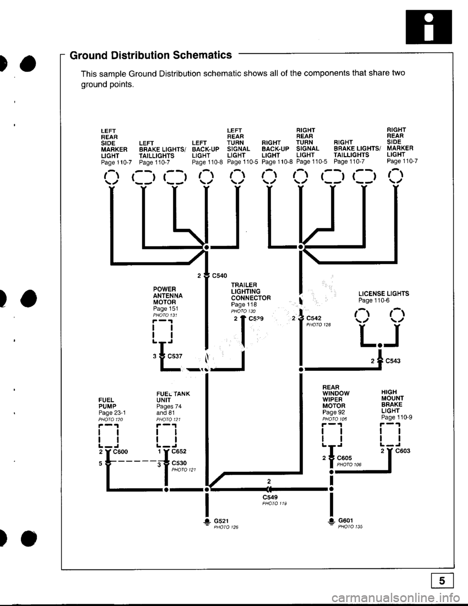
'ouno ulslnoulron Scnemarlcs -
This samDle Ground Distribution schematic shows all of the components thal share two
ground points.
LEFT RIGHT RIGHTREAR REAR REARLEFT LEFT TURN RTGHT TURN RIGHT SIDEBRAKE LIGHTS/ BACK-UP SIGNAL BACK-UP SIGNAL BRAKE LIGHTS/ MARKER
TAILLTGHTS LIGHT LIGHT LIGHT LIGHT TAILLIGHTS LIGHT
Page110-7 Page110-8 Page110-5 Page110-8 Page110'5 Page110-7 Page110-7
r--r r--t t- t-l t-t ,-t r--r r--t r-\t*-r r--r \./ \/ \./ \/ \/
I LICENSE LIGHTS
I Page 110'6
l"uo, O O
l*"''* L.J
!-.1**
FUELPUMPPage 23-1
lltl
LEFTREARstoEMARKERLIGHTPage 110-7
POWERANTENNAMOTORPage 151
tlll
:E_,
a-al
JL
c549
t\
HIGHMOUNTBRAKELIGHTPage 110-9
ttll
REARwtNDowWIPERMOTORPage 92
tlll
iIn*
a-
Ira
T!. G601
FUEL TANKUNITPages 74and 81
tltl
1 Y C652
irg c530- | puoro tzt
I
106
T+ Gs21
c603
Ground DistributiSchematics
E
)o
Page 1389 of 1681
How To Use This Manual
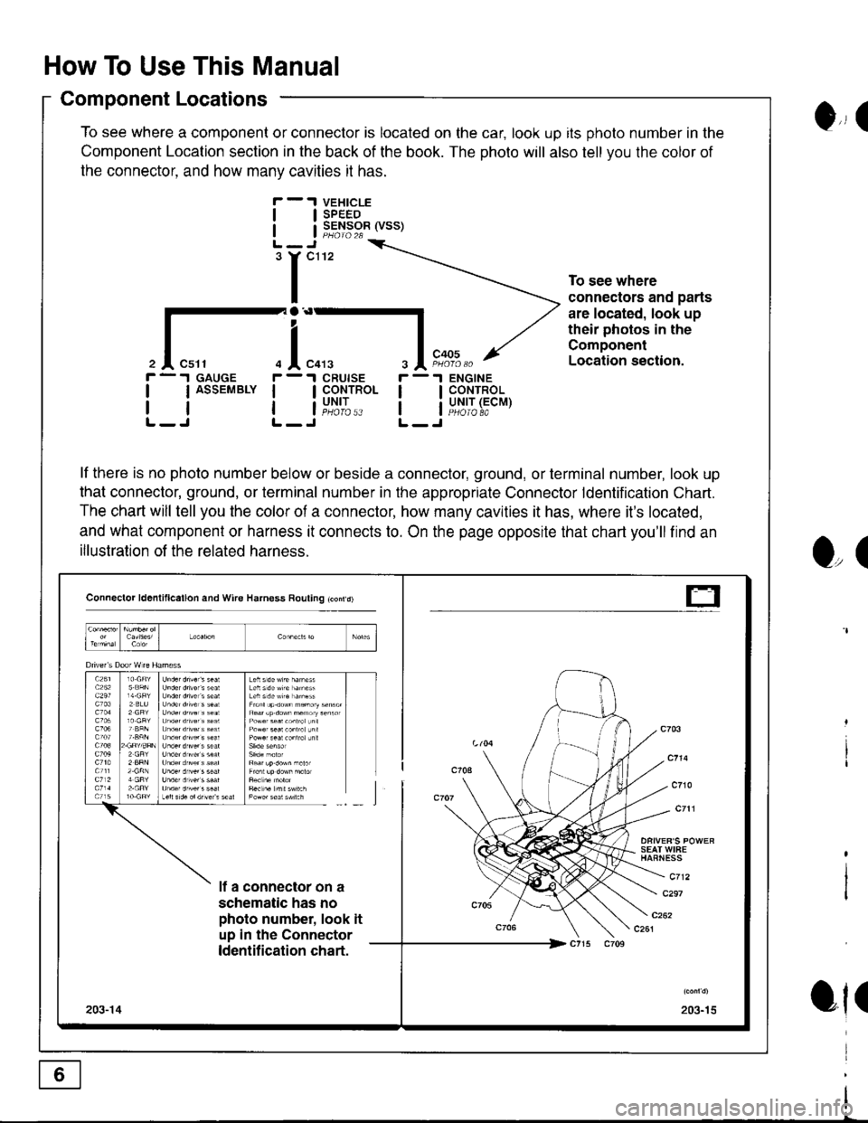
Component Locations
To see where a component or connector is located on the car, look up its photo number in the
Component Location section in the back of the book. The photo will also tell you the color of
the connector. and how manv cavities it has.
VEHICLESPEEDSENSOR (VSS)
ENGINECONTROLUNIT (ECMPHOIO 8A
0,, I
tl
tl
'r"'
To see where
connectors and parts
are located, look up
their photos in the
Component
Location section.
r -.I GAUGE
| | ASSEMBLY I
rtlL-J L-
r -'l
ll
ll
O,(
ot(
il"l,*.I CRUISE
I CoNTROL
i"u,t',:..
lf there is no photo number below or beside a connector, ground, or terminal number, look up
that connector, ground, or terminal number in the appropriate Connector ldentification Chart.
The chart will tell you the color of a connector, how many cavities it has, where it's located,
and what component or harness it connects to. On the page opposite that chart you'll find an
illustration of the related harness.
Connector ld6nlillcallon and Wire Harness Rouling tconrd)
SEAT WIFEHAFNESS
c712lf a connector on a
schematic has no
photo number, look it
up in the Connector
ldentification chart.
c297
203-15203-14
t-