Page 182 of 1681

Oil Pressure
Testing
lf the oil pressure warning light stays on with the enginerunning, check the engine oil level. It the oil level iscorrect:
Connect a tachometer.
Remove the oil pressure switch and install an oil pressure gauge.
Start the engine. Shut it off immediately if the gaugeregasters no oil pressure. Repair the problem beforecontinuing.
Allow the engine to reach operating temperature (fan
comes on at least twicel. The pressure should be:
Engine Oil Pressure:
At ldle: 70 kPa {O.7 kgficmr, tO psil
minimum
At 3,OOO rpm: 34O kPa (3.5 kgf/cmr, 50 psil
minimum
a lf oilpressure is within specifications, replace theengine oil pressure switch and recheck.
a lf oil pressure is NOT within specifications,rnspect the oil pump (see page g-11).
l�
2.
Oil Jet
lnspection(818C1, 818C5 engines
only)
1. Remove the oil jet (see pages 8 4 or 8 5) and inspectit as follows.
a Make sure rhat a 1 .1 mm (O.04 in) diameter drillwillgo through the nozzle hole fl.2 mm (O.O5 in)diameter).
a Insert the other end of the same 1 .1 mm {0.O4in) drill into the oit intake (1.2 mm (0.05 in)diameter).
Make sure the check ball moves smoothly and hasa stroke of approximately 4.0 mm (O.16 in).a Check the oil jet operation with an air nozzle. ltshould take at least 2OO kPa 12.O kg|lcm2, 2gpsi) to unseat the check ball.
NOTE: Replace the oiljet assembly if the nozzleis damaged or bent.
2. Mounting torque is critical. Be very precise when in-stalling.
Torque: 16 N.m (1.6 kgf.m, 12 lbf.ftl
1.2 mm (0.05 inl
16 N.m {1.6 kgf'm, 12 lbf.ftl
8-9
Page 1058 of 1681

J
Electrical
Speciaf Toofs ..........................23-2
Troubleshooting
Tips 8nd Precautions .......................,..,.,.,.,.,......,..., 23-3
Five-step Troubleshooting ............,......,.,.,...,..,....., 23-5
Schsmatic Svmbols ...............23-6
Wire Color Code3 .. ................. 23-6
Relay and Control Unit Locations
Engine Compartment ......,.,.................,.,.,.,.,.,,,, 23-7
Dashboard and Door .........,...........,.....,.,....,.,.... 23-8
Dashboard and Floor ......................................... 23-10
Ouarter Pan€f .,,.,...,.,..,...,,,23-12
Connector ldontification and WireHarness Routing ......,.,......23-'13
Index to Circuits and Systems
Airbag
* Integrated Control Unit .....,.,.,.....23-152* Interlock Sytem .,...,.,...........,. 23.146
Lights, Exterior
Eack-up LighB ..................23.187
Brake Ligh$ ......................23-190*Daytime Running Lights (Canada) ................... 23"164
Front Parking Lights .......................................... 23-173
Front Side Marker Lights .................................. 23-173
Front Turn Signal Lights ..................-.......,...,.,. 23-173* Hazard Warning Lights ....................,........,....... 23-192
Headlights.....23-169
23-253 powerDistribution..................... 23-5/r
Air Conditioning.....,....... Soction 21
Alternator ..........,................... 23.99
iCigarette Lighter .........23-212
*Cruise Control
Distributor
'.'.,.'.'.,.'...,,,,.,''.'.,.',.'''.' 23.277
.............................. 23.88
................... 23-90lgnition Timing ......
Indicator Lights
Key-in Reminder System
Maintenance Reminder System*Seat Belt R€mindor System .,...........................* Side Marker/Turn Signal/HazardFlashcr Svstem .................23-192
Spark Plugs ............................23-98
Starting System .....................23-74* Stereo Sound System ...,......,..........,...,......,.,.,.,..,., 23-196
Supplemental Restraint System (SRS) ................ 23-277
Vshicle Speed Sensor (VSS) ................................. 23.130r Wiper/Washer System .........................................., 23-265
*Read SRS precautions on Psge 23-283 before working
in those areas,
23-154
23.136
23"133
Page 1089 of 1681

Connector ldentification and Wire Harness Routing
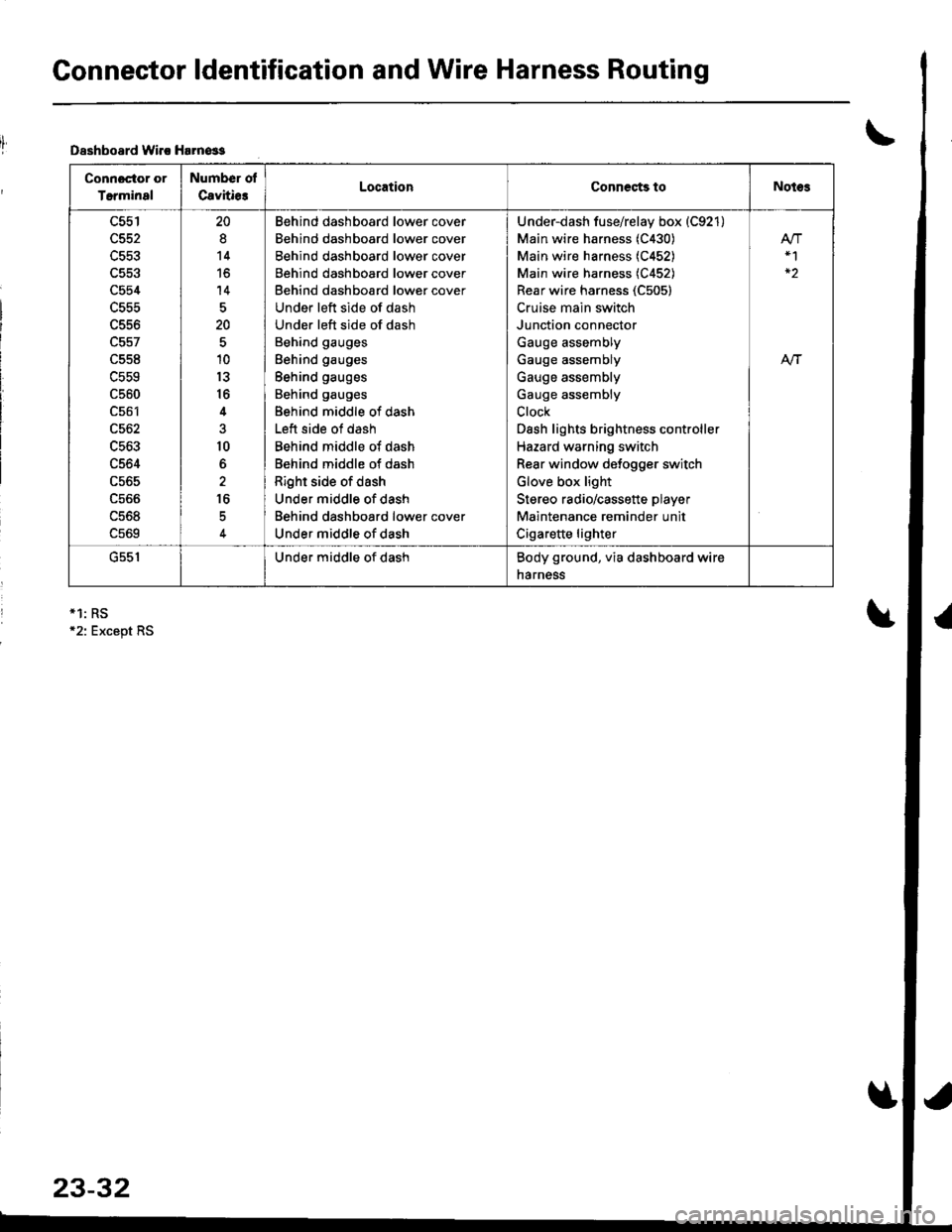
Dsshboard lvirc Harn€ss
Connoctor or
Terminal
Number ol
Cavitie3LocationCoDnects toNotes
c554
L55t'
c561
c562
c563
c564
c565
ucoo
uc06
c569
20
8
14
to
14
20
10
13
16
4
10
6
16
Behind dashboard lower cover
Behind dashboard lower cover
Behind dashboard lower cover
Behind dashboard lower cover
Behind dashboard lower cover
Under left side of dash
Under left side of dash
Behind gauges
Behind gauges
Behind gauges
Behind gauges
Behind middle of dash
Left side of dash
Behind middle of dash
Behind middle of dash
Right side of dash
Under middle of dash
Behind dashboard lower cover
Under middle of dash
Under-dash fuse/relay box (C921)
Main wire harness (C430)
Main wire harness (C452)
Main wire harness (C452)
Rear wire harness (C505)
Cruise main switch
Junction connector
Gauge assembly
Gauge assembly
Gauge assembly
Gauge assembly
Clock
Dash lights brightness controller
Hazard warning switch
Rear window defogger switch
Glove box light
Stereo radio/cassette player
Maintenance reminder unit
Cigarette lighter
At-|-
uc5 |Under middle of dashBody ground, via dashboard wire
narness
*1: RS12: Except RS
23-32
Page 1110 of 1681

J
)1 -
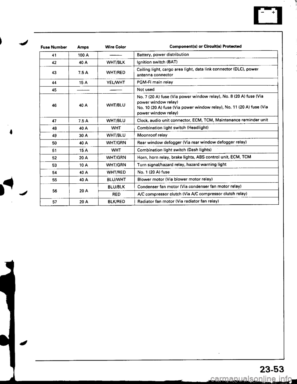
Fuso NumborAmpsWir€ ColorComponent(s) or Circuh(rl Protastcd
41100 ABattery. power distribution
4240AWHT/BLKlgnition switch (BAT)
437.5 AWHT/REDCeiling light, cargo area light, data link connector (DLCl, power
antenna connector
44't5 AYEL/WHTPGM-Fl main relay
45Not used
4640AWHT/8LU
No. 7 (20 A) fuse (Via power window relay), No. 8 (20 A) tuse (Via
power window relay)
No. 10 (20 A) fuse (Via power window relay), No. 11 (20 A) fuse (Via
power window relay)
417.5 AWHT/BLUClock,8udio unit connector, ECM, TCM, Maint€nance reminder unit
4840AWHTCombination light switch (Headlight)
4930AWHT/BLUMoonroof relay
5040AWHT/GRNRear window defogger {Via rear window defogger relay)
51154WHTCombination light switch (Dash lights)
20AWHT/GRNHorn, horn relay, brake lights, AgS control unit, ECM, TCM
10AWHT/GRNTurn signal/hazard relay, hazard warning light
5440AWHT/flEDNo. 1 (20 A) fuse
40ABLU/WHTBlower motor (Via blower motor relsy)
56204BLU/BLKCondenser fan motor (Via condenser {an motor relay)
REDA,/C compressor clutch (via Ay'c comp.essor clutch relay)
57204BLVREDRadiator f8n motor (Via radiator fan relay)
23-53
Page 1111 of 1681
Power
Circuit
Distribution
ldentification
UNDER.HOOO ABSFUSE/RELAY 8OX
ABS OUMP MO'OF CELAY
I Li,z (via ABS lail.sale telay)
L lgS moou aror un r(Va ABS lai.sale retay)
N0.62 (20A)FUSElvia ABS lai-l\sale re ay /
ABS pump motor
ABS conlrol unir (MCK)
ABS con$olunit (PMR)
Hazad warning lightTurn signal/hazard elay(Viaswilch)Horn
BRN/YEL
YEUFED
8LK - Shner molor
BLK/RED
T
G1
GmlG401
ALTERNATORwHriGRN---
WHT/GRN -No rs {7.5A1 V"LL,,r,
_f,-"*
GRNMHT -F ABS conlrollnrt
t- EcM TcM_ &eke ughts
GRN/RED - ECM
*HT,BLK --+ ig|ryJ,itil.* F^r
F UNDEF OASHvlHi.nED -I4 > FUSE FELAY BOXLz {To page 23 59)
YEITWHT - PGM.Flmain retav
T. UNDER.DASHI/HT a_U -l 'l > .uSE RELAV 8OXfro page 23 57)
ClockECM
TCMMainlenance reminder unl
MT/GRN --T Horn relav
-ol- WHTTGRN -l
BRAKE SWITCHION: Pedal depressedl
23-54
Page 1182 of 1681
J
BLKYEL
YEUBLU
A8SN0.53 (104) FUSE CONTROLlFrofi page 23A'123) UNIT
VV
II
tltlWHT/GFN BLU/REO
lonWHT€IU
I
I
I
\?
ALTERNATOR
lo'PNK
J
HAZAROWARNINGswtTcH
MENTENANCEREMINDERLIGHT0.4v,/i
lo'PNK
II
I
J
MAINTENANCEREMINDERUNIT
| 011
YEUREO
I
T
P"-:
)-
BLK
I:
G201G401
LOWENGINE OILPFESSUREINDICATORLIGHT0.4w)
23-125
)J
Page 1249 of 1681
Side Marker/Turn Signal/Hazard Flasher System
Component Location
TURf{ SIGNAL INDICATOF LIGHYS(ln the gaugo assembly)Eulb Locations, page 23-122
COMBNANON LIGHT SWTTCHReplacement. page 23-168Test, page 23-166
FUS€/RELAY BOX
HAZARD WARNING SWITCHReplacement, pago 23-195Test, pag€ 23-195
il
r-.1uuij tjt +ffi-------r--- _ ntll----------rn LJJ u
?UBN SIGNAL/HAZARD RELAYInput Test, page 23-'194
I
23-192
Page 1251 of 1681

Side Marker/Turn Signal/Hazard Flasher System
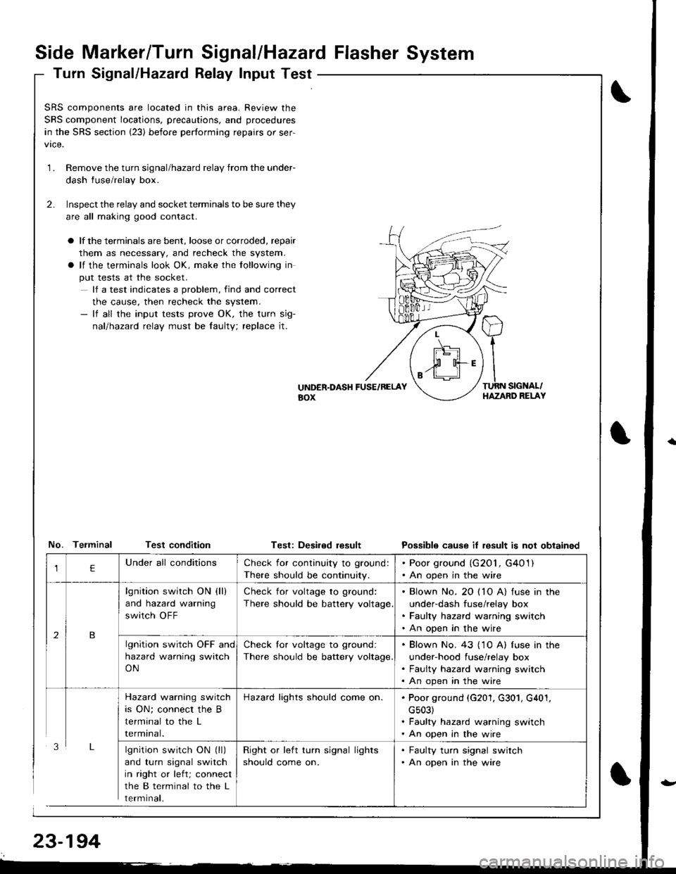
Turn Signal/Hazatd Relay Input Test
\
t
SRS components are located in this area. Review the
SRS component locations, precautions, and procedures
in the SRS section (23) before performing repairs or ser-
1.Remove the turn signal/hazard relay from the under-
dash fuse/relay box.
Inspect the relay and socket terminals to be sure they
are all making good contact.
a lf the terminals are bent, loose or corroded, repair
them as necessary, and recheck the system.
a lf the terminals look OK, make the tollowing in
put tests at the socket.
lf a test indicates a problem, find and correct
the cause, then recheck the system.- lf all the input tests prove OK, the turn sig-
nallhazad relay must be faulty; replace jt.
2.
UiTDER.DASH FUSE/RELAYaox
TURN SIGNAL/HAZAND RELAY
No. Telminal Test conditionTest: Deaired resultPossible cause it result is not obtained
lgnition switch ON (ll)
and turn signal switch
in right or left; connect
the B terminal to the L
rermtnat,
Check for continuity to ground:
There should be continuity.
. Poor ground (G201, G401). An open in the wire
lgnition switch ON (ll)
and hazard warning
switch OFF
Check for voltage to ground:
There should be battery voltage
. Blown No. 20 ( 10 A) fuse in the
under-dash fuse/relay box. Faulty hazard warning switch. An open in the wire
lgnition switch OFF and
hazard warning switch
ON
Check lor voltage to ground:
There should be battery voltage.
. Blown No. 43 ('1 0 A) f use in the
under-hood fuse/relay box. Faulty hazard warning switch. An open in the wire
Hazard warning switch
is ON; connect the B
terminal to the L
rermtnat.
Hazard lights should come on.. Poor ground (G201, G301, G401,
cs03). Faulty hazard warning switch. An open in the wire
Right or left turn signal lights
should come on.
. Faulty turn signal switch. An open in the wire