Page 65 of 1681
r.lJ
Valve Clearance
Adjustment
NOTE:
. Valves should be adjusted cold; at a cylinder head
temperature of less than 100'F (38"C).
Adjustment is the same for both intake and exhaust
valves.
. After adjusting, retorque the crankshaft pulley bolt to
177 N.m (18.0 kgf.m, 130 lbf'ft).
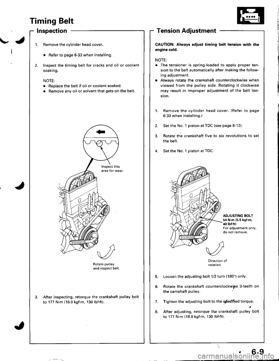
1. Remove cylinder head cover.
ADJUSTING SCREW LOCATIONS:
EXHAUST
(
"UP" MARKS
TDC GBOOVES
2. Set the No. 1 piston at top dead center (TDC) (see
page 6-12). "UP" mark on the pulley should be at
the top, and the TDC grooves on the pulley should
align with the TDC groove on timing belt back
cover. TDC mark (painted white) on the crankshaftpulley should align with pointer on the timing belt
lower cover.
Number 1 piston at TDC:
POINTER ONLOWER
TDC MAFK(P.inted whh.l
(cont'd)
6-3
Page 69 of 1681

-1,
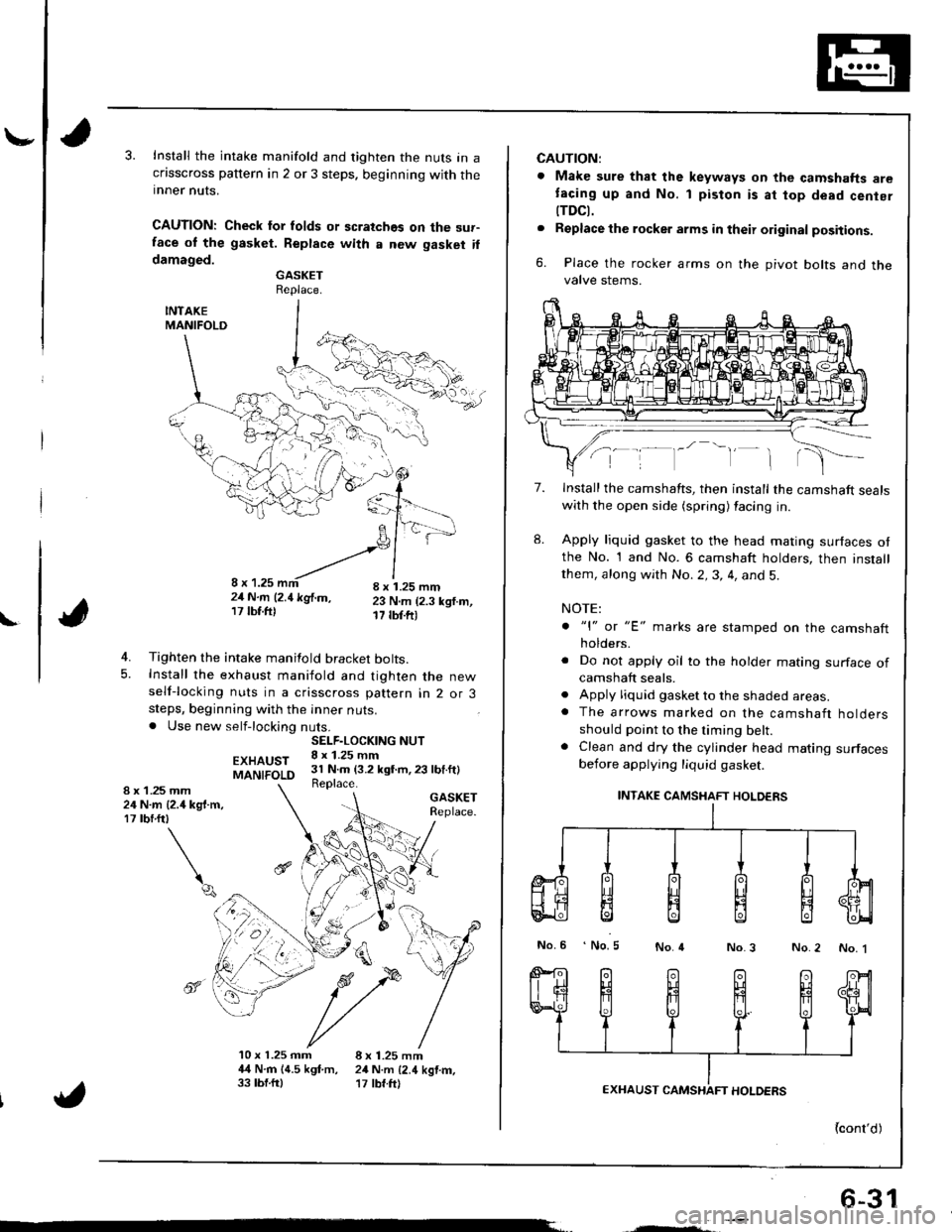
Timing Belt
lllustrated lndex
NOTE:
. Refer to page 6-12 for positioning crankshaft and pulley before installing belt.. Mark the direction of rotation on the beh before removing.
. Replace the rubber seals if there is oil leakage between the cylinder head and cover.. Do not use the middle cover and lower cover for storing removed items.. Clean the middle cover and lower cover before installation.
CAP NUT6x1.0mm9.8 N.m {'1.0 kgi.m,
WASHERReplace when damagedor deteriorated.
CYLINDER HEAD COVERRefer to page 6-33 wheninstalling.
RUBBER SEALS
7.2 tbftll
TIMING BELTInspection, page 6 9Adjustment, page 6 9Replacement, page 6,10Beplace when damagedor deteriorated,8 x 1.25 mm37 N.m (3.8 kgf.m, 27 lbf.ft)
BACK COVER
Install with concavesurface facing out.Remove any oiland clean,
ADJUSTING BOLT10 x 1.25 mm54 N.m {5.5 kgt.m, 40 lbf.ltl
MIDDLE COV€R
!6x1.0mm9.8 N.m {1.0 kgf.m,7.2lbl.ftl
6x 1.0mm9.8 N.m 11.0 kgl.m, 7.2lbf.ftl
TIMING BELTDRIVE PULLEYRemove any oilano ctean.
LOWERCOVER
CRANKSHAFTPULLEYRemove any oiland clean thetiming belt guideplate side.
6x1.0mm'11 N.m (1.1 kgf.m, 8.0 lbI.ft)
SPEED
ItEi:lufrroN {cKF)
NOTE: When installing a new crankshaft and/or new bolt:
O tighten the crankshaft pulley bott to 196 N.m (20.0 kgf.m, 145 tbf.ft),
@ loosen bolt,
@ retighten it to 177 N.m (18.0 kgnm, 130 tbnft).
PULLEY EOLT14 x 1.25 mm177 N.m (18.0 kgf.m, 130 bnftlReplacement, page 6-8
6-7
Page 71 of 1681

\-a
I
I
{
. 6-9
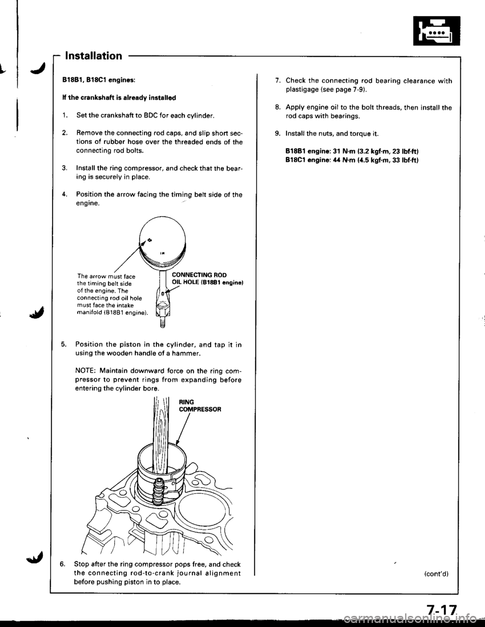
Timing Belt
Inspection
1.Remove the cylinder head cover.
o Refer to page 6-33 when installing.
Inspect the timing belt for cracks and oil or coolant
soal(n9.
NOTE:
. Replace the belt if oil or coolant soaked.
. Remove any oil or solvent that gets on the belt.
2.
Rotate pulley
and inspect belt.
After inspecting. retorque the crankshaft pulley bolt
to 177 N'm (18.0 kgf.m, 130 lbnft).
CAUTION: Always adiust iiming belt lension with the
engin€ cold.
NOTE:
. The tensioner is spring-loaded to apply proper ten-
sion to the belt automatically after making the follow-
ing adjustment.
. Alwavs rotate the crankshaft counterclockwise when
viewed from the pulley side. Rotating it clockwise
may result in improper adjustment of the belt ten-
ston.
Remove the cylinder head cover. (Refer to page
6-33 when installing.)
Set the No. I piston at TDC (see page 6-12).
Rotate the crankshaft five to six revolutions to set
the belt.
Set the No. 1 piston at TDC.
1.
2.
ADJUSTING BOLT54 N.m (5.5 kgf.m,{0 rbr.fttFor adjustment only,do not remove,
7.
8.
Direction ofrotation.
Loosen the adjusting bolt 1/2 turn (180') only.
Rotate the crankshaft counterclockwiFe 3-teeth on
the camshaft pulley
Tighten the adjusting bolt to the qdebified torque.
After adjusting. retorque the crankshaft pulley bolt
to 177 N.m {18.0 kgf.m, 130 lbf.ftl.
Page 82 of 1681
Gylinder Head
Removallcont'd)
19. Remove the side engine mount.
10 x 1.25 mm52 N.m {5.3 kgt:m, 38 lbl.ft}
20. Remove the cylinder head cover.
SIDE ENGINEMOUNT
12 x 1.25 mm74 N.m 17.5 kgt.m,sil lbtft)
CYLINOER HEADCOVER
t
L
I'
L21.
22.
Remove the timing belt (see page 6- 10).
Remove the camshaft pulleys and back cover.
CAMSHAFTPULLEYS
23. Remove the exhaust manifold.
GASKETReplace.
SELF.LOCKING NUT8 x 1.25 mm3'l N.m 13.2 kgl.m, 23 lbf.ftlReplace.
Page 93 of 1681

\-
L
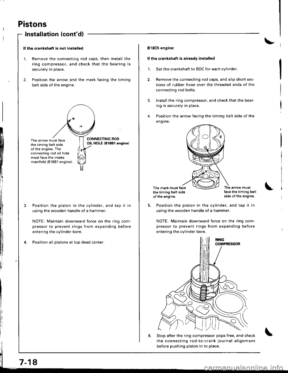
Install the intake manifold and tighten the nuts in acflsscross pattern in 2 or 3 steps. beginning with theinner nuts.
CAUTION: Check lor folds or scratches on the sur-face ol the gasket. Replace with a new gasket ildamaged.GASKETReplace.
INTAKEMANIFOLD
4. Tighten the intake manifold bracket bolts.5. Install the exhaust maniiold and tighten the newself-locking nuts in a crisscross pattern in 2 or 3steps, beginning with the inner nuts.. Use new self-locking nuts.
EXHAUSTMANIFOLD
GASKETReplace.
4
10 x 1.25 mm 8 x 1.25 mm4,{ N.rn 14.5 kgf.m, 24 N.m {2.4 kgtm,33 tbf.ftl '17 tbf.ft)
SELF.LOCKING NUT8 x 1.25 mm31 N.m (3.2 kgt m,23 lbf.ft)Replace.1 .25 mmN.m {2.4 kg{.m,rbrftt
\q
8x2417
",', r, ^-'-"-!,1,,,';-21N.m l2.1kglm, 23 N.m (2.3 ksf.m,17lbf.ftl 17 tbf.ftr
6-31
CAUTION:
. Make sure that the keyways on the camshafts aretacing up and No. 1 piston is at top dead cenier
tTDCt.. Replacethe rocker arms in their original positions.
6. Place the rocker arms on the pivot bolts and thevalve stems.
7.
8.
Install the camshafts, then install the camshaft sealswith the open side (spring) facing in.
Apply liquid gasket to the head mating surfaces otthe No. 1 and No. 6 camshaft holders, then installthem, along with No.2,3, 4, and 5.
NOTE:
. "l" or "E' marks are stamped on the camshaftholders.
. Do not apply oil to the holder mating surface ofcamshaft seals.. Apply liquid gasket to the shaded areas.. The arrows marked on the camshaft holdersshould point to the timing belt.. Clean and dry the cylinder head mating surfacesbefore applying liquid gasket.
INTAKE CAMSHAFT HOLDERS
No.6 No.5No.4No.3 No.2 No. 1
{cont'd)
Page 95 of 1681
15.
16.
17.
Install the timing belt (see page 6-12).
Adjust the valve clearance (see page 6-3).
lnstall the rubber seal in the groove of the cylinderhead cover. Seat the seal in the recesses for thecamshaft first, then work it into the groove aroundthe outside edges.
NOTE:
. Before installing the rubber seal, thoroughlyclean the seal and the groove.
. When installing, make sure the seal is seatedsecurely in the corners of the recesses with nogap.
RUEBER SEAL
18.Apply liquid gasket to the rubber seal at the eightcorners of the recesses.
NOTE:
. Use liquid gasket, Part No. 08718 - OO01 or 08718- 0003.
. Check that the mating surfaces are clean and drybefore applying liquid gasket.. Do not installthe parts if 5 minutes or more naveelapsed since applying liquid gasket. Instead,reapply liquid gasket after removing old residue.. After assembly, wait at least 30 minutes beforefilling the engine with oil.
Apply liquid gasket tothe shaded areas.
(cont'd)
6-33
Page 161 of 1681

t
Installation
Bl881, 818C1 enginos:
lf the crankshaft is already installed
'1. Set the crankshaft to BDC for each cylinder.
2, Remove the connecting rod caps, and slip short sec-
tions of rubber hose over the threaded ends of the
connecting rod bolts.
3. Install the ring compressor, and check that the bear-
ing is securely in place.
4. Position the arrow facing the timing belt side of the
eng ine.
The arrow must facethe timing belt sideot the engine. Theconnecting rod oil holemust face the intakemanjfold (81881 engine).
CONNECTING ROOOIL HOLE {81881 enginel
Position the piston in the cylinder. and tap it in
using the wooden handle of a hammer.
NOTE; Maintain downward force on the ring com-pressor to prevent rings from expanding before
entering the cylinder bore.
6. Stop after the ring compfessor pops free, and check
the connecting rod-to-crank journal alignment
betore pushing piston in to place,
7.Check the connecting rod bearing clearance withplastigage {see page 7-9).
Apply engine oil to the bolt threads. then install the
rod caps with bearings,
Installthe nuts, and toroue it.
81881 engine: 31 N.m {3.2 kgf.m, 23 lbf.ft)
BlSCt engine: il4 N.m {i[.5 kgf.m, 33 lbf.ft)
(cont'd)
7-17
Page 162 of 1681

I
i
Pistons
Installation (cont'dl
ll the crankshaft is not installed
1. Remove the connecting rod caps, then install the
ring compressor. and check that the bearing is
securely in place.
2. Position the arrow and the mark facing the timing
belt side of the engine.
ItIl
Iti
tfll|lflI[lrB
[:
i"lrt
i'
ff
ll,
illi
llillr
il
The arrow must facethe timing belt sideof the engine. Theconnecting rod oil holemust face the intakemanilold (8188'l engine).
Position the piston in the cylinder, and tap it in
using the wooden handle of a hammer.
NOTE: Maintain downward force on the ring com-
pressor to prevent rings from expanding before
entering the cylinder bore.
Position all pistons at top dead center.
7-18
818C5 engine:
ll the crankshaft is already installed
1. Set the crankshaft to BDC for each cylinder.
2. Remove the connecting rod caps, and slip short sec-
tions of rubber hose over the threaded ends of the
connecting rod bolts.
3. Install the ring compressor, and check that the bear-
ing is securely in place.
4. Position the arrow facing the timing belt side of the
eng ine.
The mark must facethe timing belt sideof the engine.
The arrow mustlace the timing beltside of the engine.
Position the piston in the cylinder, and tap it in
using the wooden handle of a hammer.
NOTE: Maintain downward iorce on the ring com-
pressor to prevent rings from expanding before
entering the cylinder bo.e.
6. Stop after the ring compressor pops free, and check
the connecting rod-to-crank journal alignment
before pushing piston in to place.