1998 HONDA INTEGRA Timing
[x] Cancel search: TimingPage 163 of 1681
I
7.
8.
9.
Check the sonnecting rod bearing clearance withplastigage (see page 7-9).
Apply engine oil to the bolt threads, then install the
rod caps with bearings.
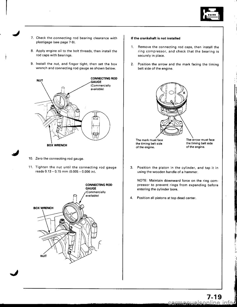
Install the nut, and finger tight, then set the boxwrench and connecting rod gauge as shown below.
CONNCCNNG RODGAUGE{Commerciallyavailable)
10.
WRENCH
Zero the connecting rod gauge.
Tighten the nut until the connecting rod gauge
reads 0.13 - 0.15 mm (0.005 - 0.006 in).
CONNECNNG HOOGAUGE
1t.
ll the crankshaft is not installed
1. Remove the connecting rod caps, then install the
ring compressor, and check that the bearing is
securely in place.
2. Position the arrow and the mark facing the timing
belt side ot the engine.
The mark must facethe timing belt sideof the engine.
Tb6 arrow must tac6th€ timing belt sideof the engine.
Position the piston in the cylinder, and tap it in
using the wooden handle of a hammer.
NOTE: Maintain downward force on the ring com-pressor to prevent rings from expanding before
entering the cylinder bore.
Position all pistons at top dead center.
Page 166 of 1681
Piston Pins
Removal
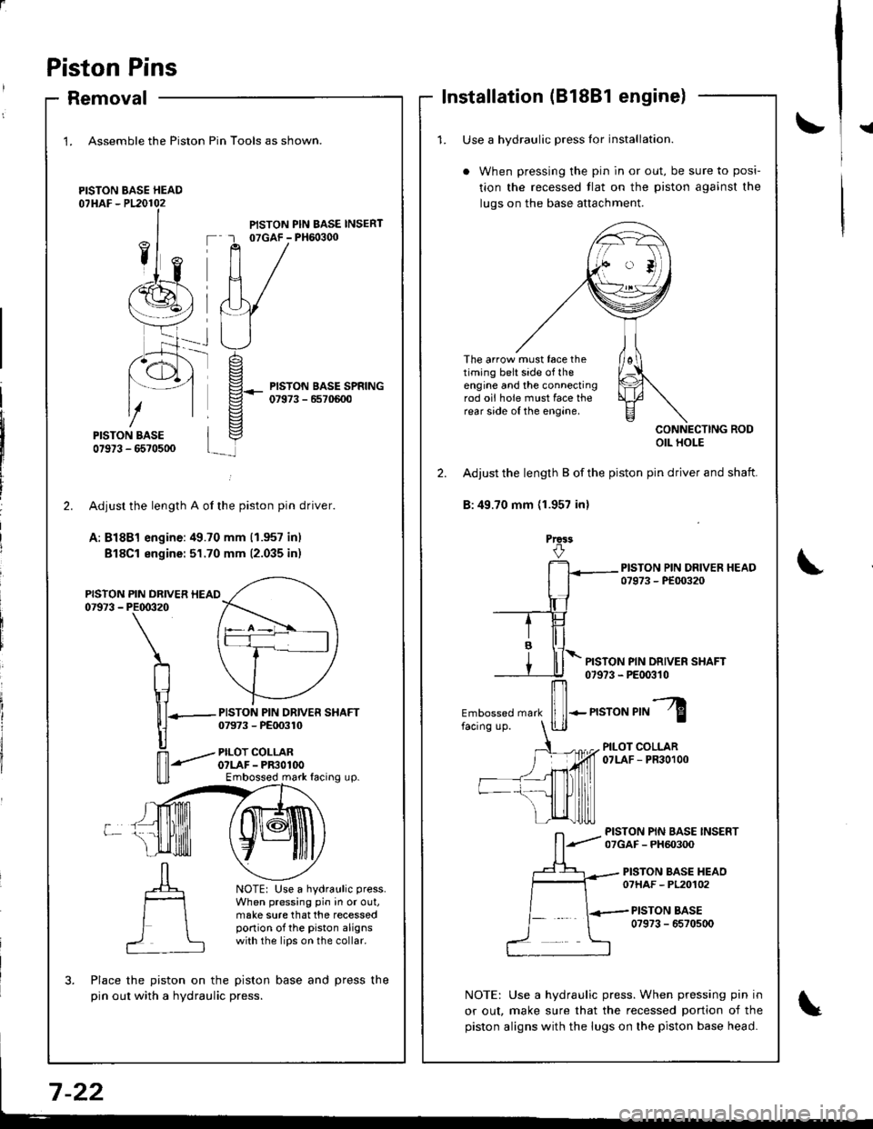
1. Assemble the Piston
PISTON BASE HEAD07HAF - P120102
Pin Tools as shown.
PISTON PIN BASE INSERT07GAF - PH6o3q)
PISTON BASE SPRING07973 - 6570600
-rt_
2.
PISTON07973 -
L
PISTON PIN DRIVER SHAFT07973 - PE00310
PILOT COLLARO?LAF - PR3OlOOEmbossed mark facing up.
NOTE: Use a hydraulic press.
When pressing pin in or out,make sure that the recessedportion of the piston alignswith the lips on the collar.
?
Adjusr the length A of the piston pin driver.
A: Bl8Bl engine:49.70 mm (1.957 inl
Bl8Cl engine: 51.70 mm (2.035 inr
PIN DRIVER HEAIPE00320
\
n
\1lll-
|]
n'-"'
Place the piston on the piston base and press the
pin out with a hydraulic press.
Installation (81881 engine)
!{1. Use a hvdraulic Dress lor installation.
When pressing the pin in or out, be sure to posi-
tion the recessed tlat on the piston against the
luqs on the base attachment.
The arrow must face thetiming belt side of theengine and the connectingrod oii hole must face therear side of the engine.
CONNECTING RODOIL HOLE
2. Adjust the length B of the piston pin driver and shaft.
B:49.70 mm (1.957 inl
Prca3
PISTON PIN DRIVER SHAFT07973 - PE00310
Embossed mark
ffi-n"ro"r,"l
PILOT COLLAR07LAF - PR30100
PISTON PIN BASE INSERT07GAF - PH60300
PISTON BASE HEAO07HAF - PL20102
PISTON BASE0?973 - 6570500
NOTE: Use a hydraulic press. When pressing pin in
or out, make sure that the recessed portion of the
piston aligns with the lugs on the piston base head.
Page 173 of 1681
Oil Seal
Installation
The seal surface on the block should be dry.
Apply a light coat of oil to the crankshaft and
the lip of the seal.
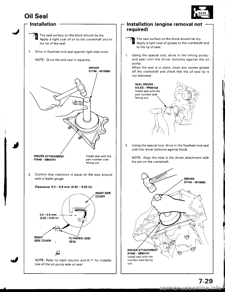
1. Drive in tlywheel end seal against right side cover.
NOTE: Drive the end seal in squarely.
DRIVER07749 - 0010000
Confirm that clearance is equal all the way around
with a feeler gaug€.
Clearance: 0.5 - 0.8 mm {0.02 - 0.03 inl
RIGHT SIDECOVER
lnstallation (engine removal not
requiredl
The seal surface on the block should be dry.
Apply a light coat of grease to the crankshaft and
to the lip of seal.
1. Using the special tool, drive in the timing pulley-
end seal until the driver bottoms against the oil
pump.
When the seal is in place, clean any excess grease
off the crankshalt and check that the oil seal lip is
not distoned.
SEAL DRIVER07LAD. PR4O1OAlnstall seal with thepan numberfacing out.
Using the special tool, drive in the flywheel end seal
untilthe driver bottoms aqainst block.
NOTE: Align the hole in the driver attachment with
the pin on the crankshaft.
DRIVER077{9 - 0010000
DRIVER ATT07948 - 5800101lnstall sealwith thenumber side facinqou!.
'tvA,)/ )
DBIVER ATTACHMENT07948 - 5800101Install sealwith thepan number sidefacang out.
[7Fd
NOTE: Refer to right column and 8-11
tion of the oil pump side oil seal.
for installa-
Page 184 of 1681

3.
Removal/lnspection/lnstallation
Drain the engine oil.
Turn the crankshatt and align the white groove onthe crankshatt pulley with the pointer on the lowercover.
Remove the cylinder head cover and middle cover.
Remove the power steering pump belt, air condition-er belt and the alternator belt.
Remove the crankshaft pulley and remove the low-er cover.
6. Remove the timing belt,
7. Remove the drive pulley.
8. Remove the oil pan and oil screen.
9. Remove the oil pump.
OIL PUMP
OIL PAN
8-1
'10. Remove the screws from the pump housing, thenseparate the housing and cover.
1 1 . Check the inner-to outer rotor radial clearance on thepumD rotor.
Inner Rotor-to-Outei Rotor Radial ClearanceStandard (Newl: O.04-O.16 mm
lO.OO2-O.O06 int
Service Limir: 0.20 mm {0.O08 in)
12. Check the housing-to-rotor axial clearancepump rotor.
Housing-to-Rotor Axial Clearance
Standard (New): 0.02-0.07 mm(0.0O1 -O.003 in)
Service Limit: O.15 mm (0.006 inl
on tne
1
Page 205 of 1681

Inspection
Remove the timing belt (81881 engine: see page 6-10, B'l8Cl,818C5 engines: see page 6-48).
Tu.n the water pump pulley counterclockwise.Check that it turn freely.
Check for sign6 of seal leakage.
NOTE: A small amount of "weeping" trom thebleed hole is normal.
BLEED HOLE
Remove the timing belt (81881 engine: see page 6-
10,818C1, Bl8C5 engines: see page 6-48).
Remove the camshaft pulleys and the back cover(B'1881 engine: see page 6-20, 818C1, 818C5
engines: see page 6-60).
Remove the water pump by removing flve bolts.
NOTE: Inspect, repair and clean the O-ring groove
and mating surface with the cylinder block,
Replacement
6 x 1.0 mm12 N.m 11.2 kgt.m,8.7 tbf.tt)
4. Install the water pump in the reverse order ofremoval.
a Keep the O-ring in position when installing.a Clean the spilled engine coolant.
BLEED HOL€
10-1 1
Page 241 of 1681
Troubleshooting
Troubleshooting Procedures (cont'd)
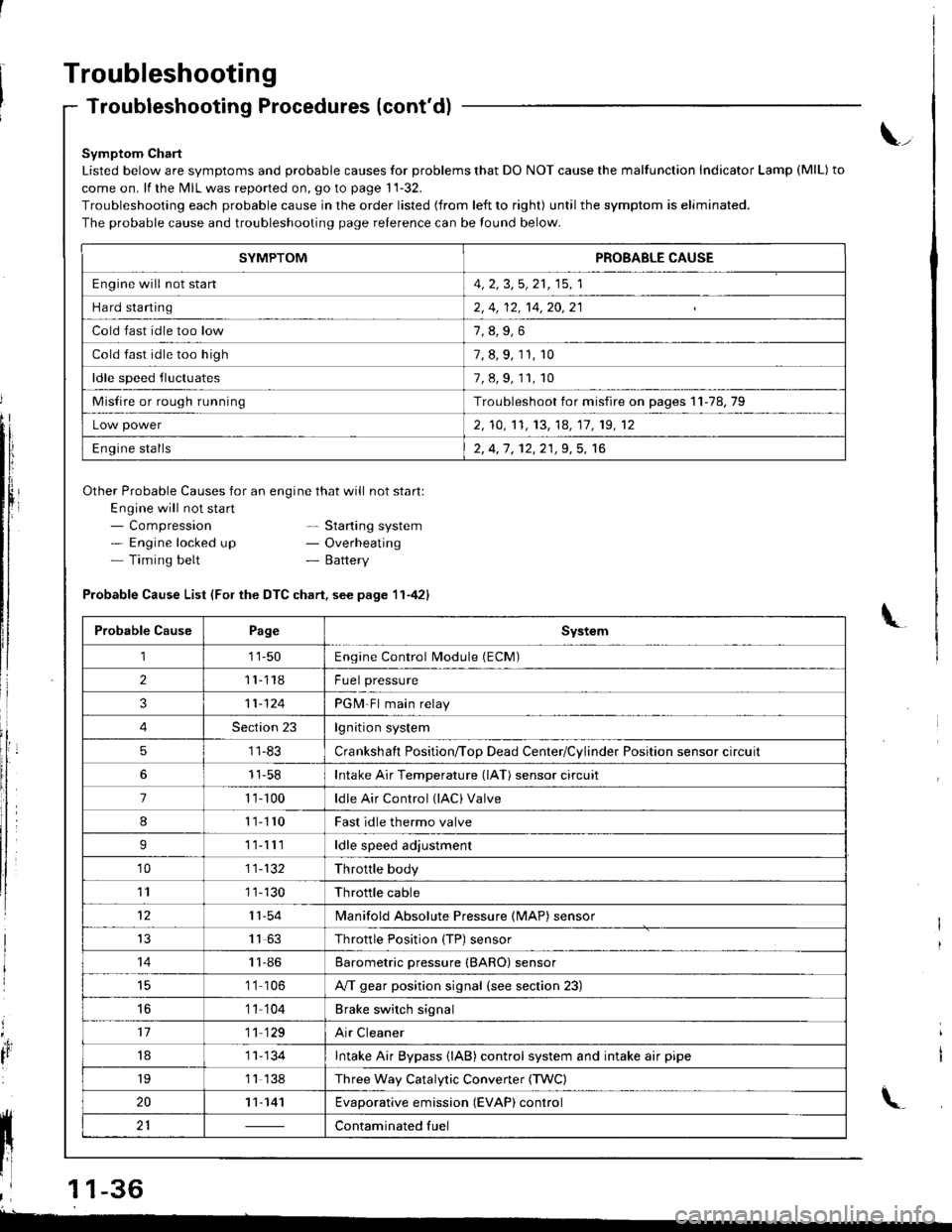
Symptom Chart
Listed below are symptoms and probable causes for problems that DO NOT cause the malfunction Indicator Lamp (MlL) to
come on. lf the MIL was reported on, go to page 11-32.
Troubleshooting each probable cause in the order listed (from left to right) until the symptom is eliminated.
The probable cause and troubleshooting page relerence can be found below.
Other Probable Causes for an engine that will not start:
Engine will not sta rt- Compression- Engine locked up- Timing belt
\_
- Starting system- Overheating- Battery
'4,
It
Probable Cause List (For the DTC chart. see page 11-421
Probable CausePageSystem
111-50Engine Control Module (ECM)
211118Fuel pressure
311-124PGM-Fl main relay
4Section 23lgnition system
51 1-83Crankshaft Position/ToD Dead Center/Cylinder Position sensor circuit
11-58Intake Air Temperature (lAT) sensor circuit
71 '�t- 100ldle Air Control (lAC) Valve
811110Fast idle thermo valve
I11lllldle speed adjustment
'1011-132Throttle body
111 1-130Throttle cable
1211-54lvlanifold Absolute Pressure {MAP) sensor
IJ1163Throttle Position {TP) sensor
1411-86Barometric pressure (BARO) sensor
1 '1 106A/T gear position signal {see section 23)
16'1 1 104Brake switch signal
1711 129Air Cleaner
181 1- 134Intake Air Bypass {lAB} control system and intake air pipe
19'1 1 138Three Way Catalytic Convener (TWC)
2011-141Evaporative emission (EVAP) control
21Contaminated fuelll ll 21 | - | cont"-in"t"o tu"
11 l-
I
,l 11-36
-
SYMPTOMPROBABLE CAUSE
Engine will not stan4, 2, 3,5, 21, 15, 1
Hard starting2, 4, 12, 14,20,21
Cold fast idle too low
Cold fast idle too high7, 8, 9, 11, r0
ldle speed fluctuates7,8,9,11,10
Misfire or rough runningTroubleshoot for misfire on pages 11-78,79
Low power2, 10,'t1, 13, 14, 17, 19, 12
Engine stalls2, 4,1 , 12,21,9, 5, 16
Page 243 of 1681
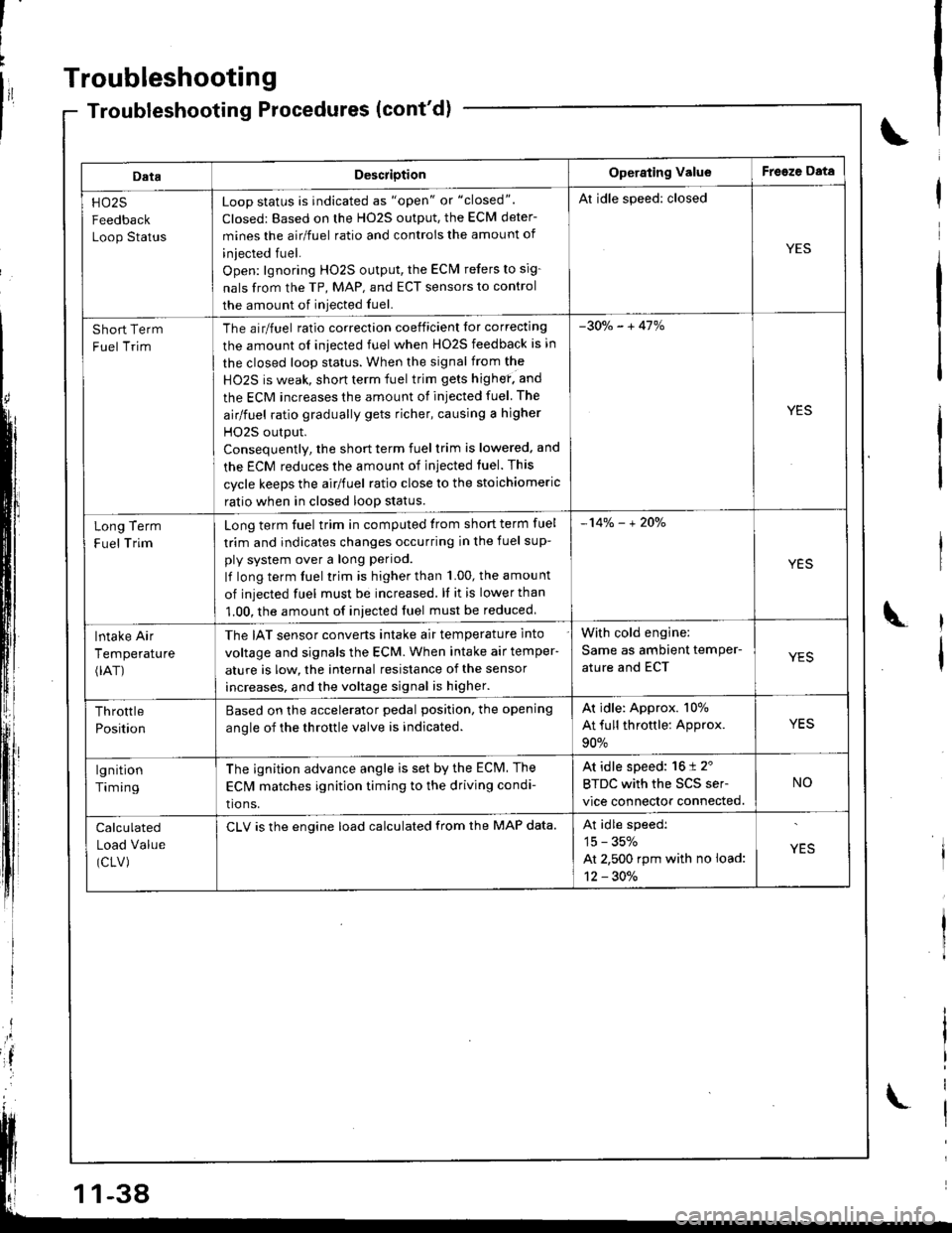
Troubleshooting
DataDescriotionOperating ValueFreeze Data
HO25
Feedback
Loop Status
Loop status is indicated as "open" or "closed".
Closed: Based on the H02S output, the ECM deter-
mines the airlfuel ratio and controis the amount of
iniected fuel.
Open: lgnoring HO2S output, the ECM refers to sig-
nals from the TP, MAP, and ECT sensors to control
the amount of iniected fuel.
Al idle speed: closed
YES
Short Term
Fuel Trim
The airlfuel ratio correclion coeificient lor correcting
the amount ol iniected fuel when HO2S feedback is in
the closed loop status. When the signal from the
HO2S is weak, short term fuel trim gets highef. and
the ECM increases the amount of injected fuel The
airlfuel ratio gradually gets richer, causing a higher
HO2S output.
Consequentlv, the short term fuel trim is lowered, and
the ECM reduces the amount of injected tuel. This
cycle keeps the airlfuel ratio close to the stoichiomeric
ratio when in closed loop status.
-30o/" - + 41%
YES
Term
Trim
Long
F uel
Long term fuel trim in computed trom short term fuel
trim and indicates changes occurring in the fuel sup-
ply system over a long period.
lf long term fuel trim is higher than 1.00, the amou nt
of injected fuel must be increased. ll it is lower than
1.00, the amount of iniected fuel must be reduced
-14% - + 2Oo/"
YES
lntake Air
Temperature(rAT)
The IAT sensor converts intake air temperature into
voltage and signals the ECM. When intake air temper-
ature is low, the internal resistance of the sensor
increases, and the voltage signal is higher.
With cold engine:
Same as ambient temPer-
ature and ECTYES
Throttle
Position
Based on the accelerator pedal position. the opening
anole of the throttle valve is indicated.
Ar idle: Approx. 107o
At full throttle: Approx.
90%
YES
lgnition
Timing
The ignition advance angle is set by the ECM. The
EClvl matches ignition timing to the driving condi-
tio ns.
At idle speed: 16 t 2'
BTDC with the SCS ser-
vice connector connected.
NO
Calculated
Load Value
(CLV)
CLV is the engine load calculated from the MAP data.At idle speedi
15 - 35%
At 2,500 rpm with no load:
12 - 30./.
YES
-38
Page 248 of 1681
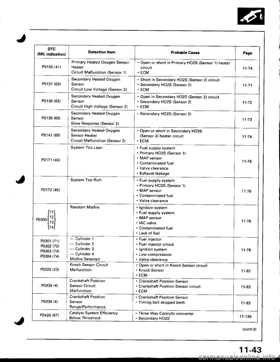
DTC(MlL indicationlDeteciion ltemProbable CausoPage
P013s {41)
Primary Heated Oxygen Sensor
Heater
Circuit Malfunction {Sensor '1)
. Open or shon in Primary HO2S (Sensor 1) heater
circuit. ECM1't-74
P0137 (63)Secondary Heated Oxygen
Sensor
Circuit Low Voltage (Sensor 2)
Short in Secondary HO2S (Sensor 2) circuit
Secondary H02S {Sensor 2)
ECM11-7'l
P0138 {63)
Secondary Heated Oxygen
Sensor
Circuit High Voltage (Sensor 2)
Open in Secondary HO2S (Sensor 2) circuit
Secondary HO2S (Sensor 2)
ECM
P0139 (63)Secondary Heated Oxygen
Sensor
Slow Response (Sensor 2)
Secondary HO2S (Sensor 2)
P0141 (651Secondary Heated Oxygen
Sensor Heater
Circuit Malfunction (Sensor 2)
. Open or short in Secondary HO2S(Sensor 2) heater circuit. ECM11-'14
P0171 (45)
System Too LeanFuel supply system
Primary HO2S {Sensor I )MAP sensor
Contaminated fuel
Valve clearance
Exhaust leakage
11-76
P0172 t45l
System Too RichFuel supply system
Primary HO2S (Sensor 1)
MAP sensor
Contaminated fuel
Valve clearance
11.76
,...,{iil
174l
Random Misfirelgnition system
Fuel supply system
MAP sensor
IAC valve
Contaminated fuel
Lack offuel
't 1-78
P0301 (71)
P03Q2 l'121
P0303 (73)
P0304 (74)
- Cylinder 1- Cylinder 2- Cylinder 3- Cylinder 4
Misfire Detected
Fuel injector
Fuel injector circuit
lgnition system
Low compression
Valve clearance
11-79
P0325 {23)
Knock Sensor Circuit
MalfunctionOpen or short in Knock Sensor circuit
Knock Sensor
ECM11-82
P0335 (4)Crankshaft Position
Sensor Circuit
Malfunction
Crankshaft Position Sensor
Crankshaft Position Sensor circuit
ECM1 1-83
P0336 (4)Crankshaft Position
Sensor
Range/Performance
. Crankshaft Position Sensor. Timing belt skipped teethIl-83
P0420 (67)Catalyst System Efficiency
Below Threshold
. Three Way Catalytic converter. Secondary HO2S11-139
(cont'd)
11-43