1998 HONDA INTEGRA fog light
[x] Cancel search: fog lightPage 303 of 1681

ldle Control System
ldle Control System
i P0505 | fne scan tool indicates Diagnostic Trouble Code (DTC) P0505: ldle control system malfunction,
NOTE: ll DTC Pl508 is stored at the same time as DTC P0505, troubleshoor DTC P1508 first. then troubleshoot DTC P0505.
Possible Cause
. IAC valve mechanical malfunctiorr
. Fast idle thermo valve malfunction (A"/T)
. Throttle body clogged port, improper adjustment
. Intake manifold, gasket leakage
. Intake air hose loose, leakage
a Vacuum hoses leakage
. ECT sensor incorrect output
. Throttle Position sensor incorrect output
Troubleshooting Flowchart
Problem verification:1. Start the engine. Hold theengine at 3,000 rpm wath noload 1in Park or neutral) untilthe radiator fan comes on,then let it idle.2. With the scan tool, check thefollowing items.- Throttle position should beapprox. 10% with the throttle fully closed.Engine coolant tempera-ture should be 116 212F(80 - 100'c).lf they are not within thespec., repair the faulty sensor crrcuft,3 Check the engine speed atidle with no-load conditions:headlights, blower fan, reardefogger, radiator fan, and airconditioner are not operating,
- The MIL has been reported on.- DTC P0505 is stored.
ls it 750 t 50 rpm (81881,
818C1 engines), 800 I 50 rpm(818C5 engine)?
Intermittent failur6, svstsm is OKat this tim€.
ls it 550 rpm (81881,818C1
engines), 600 rpm {818C5enginelor less?
-98
(To page 11'99)(To page 11-99)
Page 306 of 1681

This signals the ECM when the Alternator (ALT) is charging.
Alternator (ALT) FR Signal
Check lor a short in th€ wire {ALTF line):1. Oisconnect the ALT GRN 4P(3P)* connector from the ALT.2. Turn the ignition switch ON {ll).3. Measure voltage between ECMconnector terminals C17 and A9.
ECM CONNECTORSA t32Pt
LG1
c 13lPl
ALT F(WHT/FEDI
Wire side of female terminals
ALT GRN 4P CONN€CTOR {C119}
JUMPER WIRE
Wire side of female terminals
ALT GRN 3P CONNECTOB {C119)*
JUMP€RWIRE
Wire side ot female terminals
12 15 t6 rr t8 19I
?
oALT F(WHT/REOI
23aI10
t112t3t5l6r819 ,/21
./,/,/2a29
[,ALT FIWHT/RED)
12339
11 12l517 tla19 ,/21
Inspection of ALT FR Signal.
Check for a shon in the wire {ALTF line):1. Turn the ignition switch OFF.2. Disconnecl the negative baatery cable from the battery.3. Disconnect the ECM connectorc (31P).
4. Check for continuity betweenbody ground and ECM con-nector terminal C17.
ls there approx.5 V?
Check the operation ofthe ALT:1. Turn the;Onition switch OFF-2. Reconnect the ALT GRN 4P(3P)* connector to the ALT.3. Start the engine. Hold theengine at 3,000 rpm wkh noload {in Park or neutral) untilthe radiator fan comes on,then let it idle.4. Measure voltage bet/veen ECMcon nector termina ls C17 and A9.
Ropair short in the wir6 betweenth6 ECM (C17) and the ALT.
Substitute a known-good ECMand recheck. It prescribed voltagGis now available, replace th€ origi-nal ECM.
Does the voltage decrease whenheadlights and rear defogger areturned on?ALT FR signal is OK.
Check tor an open in the wire {ALTF line):1. Turn the ignition switch OFF-2. Disconnect the negative bat-tery cable from the battery.3. Disconnect the ECM connector C (31P).
4. Disconnect the ALT GRN 4P(3Pi* connector from the ALT.5. Connect the ALT GRN 4P (3p)*
connector terminal No. 4 (No.'l)* to body ground with a
6. Check for continuity betweenbody ground and ECM connector terminal C17.
Ropair open wire bstw€an theECM {C17} and rhe ALT.ls there continuity?
ri Canada
11-101
Page 316 of 1681

ldle Speed Setting
IDLEADJUSTINGSCREW
7.
6.Turn the ignition switch OFF.
Reconnect the 2P connectors to the IAC valve and
the EVAP purge control solenoid valve, then do the
ECM reset procedures.
Restart and idle the engine with no-load conditions
for one minute, then check the idle speed.
NOTE: (Canada) Pullthe parking brake lever up.
Start the engine, then check that the headlights are off.
ldle speed should be;
Bl88l €ngine:
Mfi750 i 50 rpm
A/T750150 rpm (in Park or neutral)
818C1 engine:750 i 50 rpm
818C5 engine: 800 i 50 rpm
NOTE: 81881, Bl8Cl engines - It the idle speed
increases to *1rpm, this means the EVAP system ispurging the canister. To stop the purging termporarily.
raise the engine speed above 1,000 rpm with the
accelerator pedal, then slowly release the pedal.
*1: 81881 engine
M/T: 820 i 50 rpm
Ay'T: 840 t 50 rpm
818Cl engine
850 I 50 rpm
(cont'd)
Inspection/Adiustmont
NOTE:
. When setting the idle speed, checkthe following items:- The MIL has not been reported on.- lgnition timing
Spark plugs- Air cleaner- PCV system
. (Canada) Pull the parking brake lever up. Start the
engine, then check that the headlights are off.
1. Start the engine. Hold the engine at 3,000 rpm with
no load (in Park or neutral) until the radiator fan
comes on, then let it idle,
Connect a tachometer.
Disconnect the 2P connectors from the ldle Air
Control (lAC) valve and the EVAP purge control
solenoid valve.
2.
5.
if the engine stalls, restan the engine with the accel
erator pedal slightly depressed. Stabilize the rpm at
1,000, then slowly release the pedal until the engine
idles.
Check idling in no-load conditions: headlights, blower
fan, rear defogger, radiator fan, and air conditioner
are not ope€tlng.
ldlo speed should be;
B188l engine:
Mlf480 :l 50 rpm
A/T480 i 50 rpm (in Park or neutral)
B18C1 engine: /t80 t 50 rpm
818C5 sngine:550 t 50 rpm
lf necessary, adjust the idle speed, by turning theidle adjusting screw.
After adjusting the idle speed, recheck the ignition
timing {see section 23). lf it is out of spec, go back
to steo 4.
Page 343 of 1681

t"iI
Emission Gontrol System
System Description
Three Way Catalytic Converter (TWCI
\
t
The emission control system includes a Three Way
Catalytic Converter (TWC), Positive Crankcase Ventilation
(PCV) system and Evaporative Emission (EVAP) Control
system. The emission control system is designed to meet
tederal and state emission standards.
InsDeciion
!@@ Do not smoke during this procedure. Keep
any open llame away from your work area.
1. Start the engine. Hold the engine at 3,000 rpm with
no load {in Park or neutral) until the radiator fan
comes on, then let it idle.
2. Connect a tachometer.
Check and adjust the idle speed, if necessary (see
page '11-11 ! ).
Warm up and calibrate the CO meter according to the
meter manufacturer's instructions.
Check idle CO with rhe headlights, heater blower,
rear window defogger, cooling fan, and air condition-
er off.
NOTE: {Canada) Pull the parking brake lever up.
Start the engine, then check that the headlights are
olf.
CO meter should indicste 0.17o maximum.
DescriDtion
The Three Way Catalytic Converter {TWC) is used to convert hydrocarbons (HC), carbon monoxide (CO), and oxides of
nitrogen (NOx) in the exhaust gas, to carbon dioxide (COr), dinitrogen {Nr) and water vapor.
Bl8Cl engine l818Bl, 818C5 engines is similar):
FRONT OFVEHICLE
PRIMAEYHEATEDOXYGEN SENSORIPRIMARY HO2S}
HOUSING
WAYCATALYSTS
SECONOARYHEATEDOXYGEN SENSOR{SECONDARYH02St
\
Page 910 of 1681

Rear pillar trim panel/Rsar shelf trim panel/Real shelt
removal:
1. Remove both seat-back side bolsters {see page 20-
113).
2. Remove the upper portion of the rear door sill mold-
ing, then pull the rear door trim away on each side.
> : Clip locations, 2
REAR PILLAR TRIM PANEL
SII-I MOLDING
3. Remove both rear pillar trim panels.
> | Clip locations, 12
NOTE: When installing, make surethe rear window defogger wireharness is routed properly.
1
I
,
4. Remove the rear shell trim panel.
V: Clip locations, 2
5. Slip the rear seat belt through the slit in the rear shelf.
REAR SHELF
Remove the seat lock cover (see page 20 113) and
high mount brake light (see section 23).
20-95
Page 1077 of 1681

Connector ldentification and Wire Harness Routing
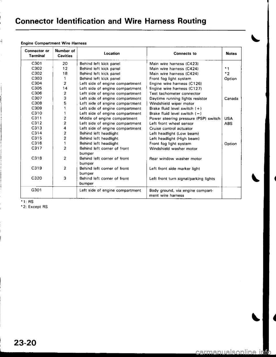
Engine Compartment Wire Halness
nll
Connectoa ot
Terminal
Number of
CavitiesLocationConnects toNotes
c301
c302
c 302
c303
c304
c306
c307
c308
c309
c310
c3l 1
c312
c314
c316
c317
c318
c319
c320
20
't8
1
14
2
3
5
1
1
2
2
4
2
2
1
2
2
2
3
Behind left kick panel
Behind left kick panel
Behind left kick panel
Behind left kick panel
Lett side of engine compartment
Lett side of engine companment
Lett side of engine compartment
Left side of engine compartment
Left side of engine compartment
Left side of engine compartment
Left side of engine compartment
Middle of engine compartment
Lett side of engine companment
Left side of engine compartment
Behind left headlight
Behind left headlight
Behind left headlight
Behind left corner of front
DUmper
Behind left corner ol front
bumper
Behind lett corner of front
bumper
Behind left co.ner of lront
bumper
Main wire harness (C423)
Main wire harness {C424)
N4ain wire harness (C424)
Front fog light system
Engine wire harness (C126)
Engine wire harness (C'127)
Test tachometer connector
Daytime running lights resistor
Windshield wiper motor
Brake f luid level switch (+ )
Brake f luid level switch ( - )
Power steering pressure (PSP) switch
Lett front wheel sensor
Cruise control actuator
LeIt headlight (Low beam)
Lett headlight {High beam)
Front fog light system
Windshield washer motor
Rear window washer motor
Left front side marker light
Left front turn signal/parking lights
Option
Canada
USA
ABS
Option
G301Lelt side of engine compartmentBody ground, via engine compart-
ment wire harness
23-20
Page 1083 of 1681

Connector ldentification and Wire Harness Routing
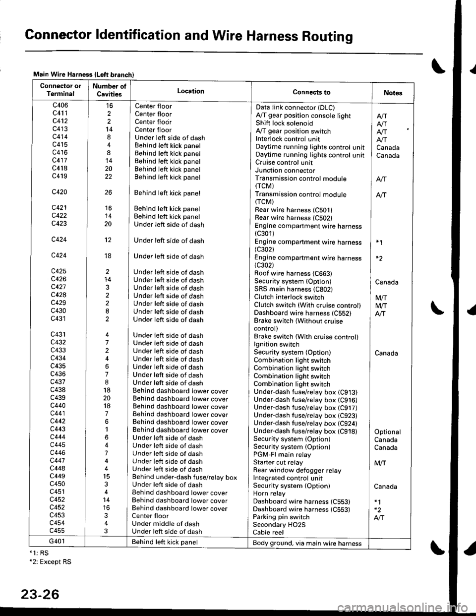
Main Wire Hsfness {Left branch}
Connector ol
TerminalNumber ol
CavitiesLocationConneqts toNot6s
c406
c41 1
c4't2
c413
c414
c415
c416
c417
c4l8
c419
c420
c421
c422
c423
c424
c424
c425
c426
c427
c428
c429
c430
c431
c43'rc432
c433
c434
c435
c436
c431
c438
c439c440
c441
c442
c443
c444
c445
c446
c447
c44ac449
c450
c451
c452
c452
c453
c454c455
16
2
2
14
4
8
14
20
22
26
Center floor
Center floorCenter flodrCenter floorUnder left side of dashBehind Ieft kick panel
Behind left kick panel
Behind left kick panel
Behind left kick panel
Behind left kick panel
Behind left kick panel
Behind left kick panel
Behind left kick panel
Under left side of dash
Under left side of dash
Under left side of dash
Under left side of dashUnder left side of dashUnder left side of dashUnder left side of dashUnder left side of dashUnder left side of dashUnder left side of dash
Under left side of dashUnder left side of dashUnder left side of dashUnder left side of dashUnder left side of dashUnder left side of dashUnder left side of dashBehind dashboard lower coverBehind dashboard lower coverBehind dashboard lower coverBehind dashboard lower coverBehind dashboard lower coverBehind dashboard lower coverUnder leit side of dashUnder left side of dashUnder left side of dashUnder left side of dashUnder left side of dashBehind under-dash fuse/relay boxUnder left side of dashBehind dashboard lower coverBehind dashboard lower coverBehind dashboard lower coverCenter floorUnder middle of dashUnder left side of dash
Data Iink connector (DLC)
A,/T gear position console lightShift lock solenoidAy'T gear position switchInterlock control unitDaytime running lights controlOaytime running lights controlCruise control unitJunction connectorTransmission control module(rcM)
Transmission control module
{TCM)Rear wire harness (C501)
Rear wire harness (C502)
Engine compartment wire harness(c301)
Engine companment wire harness I *1
(c3021 IEngine compartment wire harness(c302) lRoof wire harness {C663} |Security system {Option) | CanaAaSRS main harness (C802) |Clutch interlock switch I VnClutch switch (With cruise control) M/TDashboard wire harness (C552) AlTBrake switch lwithout cruise Icontrol) |Brake switch (With cruise control)lgnition switch ISecurity system {Option) CanadaCombination light switch /Combination light switch ICombination light switchCombination light switchUnder-dash fuse/relay box (C913)
Under-dash fuse/relay box (C916)
Underdash fuse/relay box (C917)
Under-dash fuse/relay box (C923)
Under-dash fuse/relay box (C924) |Under-dash fuse/relay box {C918) I OptionalSecurity system (Option) CanadaSecurity system (Optionl CanadaPGM-Fl main relayStarter cut relay ] M,.fRear window defogger relay IIntegrated control unitSecurity system (Option) CanadaHorn relay
Dashboard wire harness (C553)
Dashboard wire harness {C553) | -2
Parking pin switch I A,"ISecondary HO2S
Cable reel
Afi
I Atr
lf[
unit ] Canadaunit I Canada
16
14
20
't2
ti
I'
li
ll
li
+4
3
G401 Behind teft kick panelBody ground, via main wire harness*1: RS+2: Except RS
23-26
Page 1087 of 1681

Connector ldentification and Wire Harness Routing
Connector or
Terminal
Numbel of
CavitiesLocationConnects toNotes
c501
c502
c503
c504
c505
c506
c507
c508
c509
c5l0
c511
c512
c513
c514
c515
c517
c518
c519
c520
c521
c522
c523
c527
c528
c529
c530
c531
c532
c533
c534
c535
cs36
14
8
14
2
1
1
8
3
1
2
2
1
20
20
3
2
6
4
2
4
6
6
1
1
2
1
1
4
2
4
Behind left kick panel
Behind left kick panel
Behind dashboard lower cover
Behind dashboard lower cover
Behind dashboard lower cover
Driver's door
Center floor
Center floor
Left B-pillar
Fuel tank
Fuel tank
Right B pillar
Above right side of trunk
Above left side of trunk
Left quarter panel| .{+ ^',rrrar ^rnal
Left quarter panel
Left side corner of trunk
Above center of trunk
Left side corner of trunk
Left rear corner of trunk
Right rear corner o{ trunk
Right rear corner ot trunk
Lelt rear door
Right rear door
Left quarter panel
Left side of rear window
Above right side of trunk
Right quarter panel
Right side of rear window
Left side of trunk lid
Center of trunk lid
Right side of trunk lid
lvlain wire harness (C421 )
lvlain wire harness (C422)
Underdash fuse/relay box (C912)
Under dash fuse/relay box (C915)
Dashboard wire harness (C554)
Driver's door wire harness (C6Ol)
Driver's seat belt switch
Parking brake switch
Driver's door switch
Fuel pump
Fuel gauge sending unit
Front passenger's door switch
Right rear speaker
Left rear speaker
Noise condenser
Connector C517
Connector C516
Power antenna motor
Trunk light
Trailer lighting connector
Left outer taillight
License plate lights
Right outer taillight
Lett rear door wire harness
(c651)
Right rear door wire harness
1C656)
Left rear door switch
Rear window defogger {+ )
High mount brake light
Right rear door switch
Rear window detogger (- I
Left inner taillight
Trunk latch switch
Right inner taillight
G501
G502
G503
Behind left kick panel
Left side of tloor
Above center of trunk
Body ground, via rear wire
harness
Body ground, via rear wire
harness
Body ground, via rear wire
harness
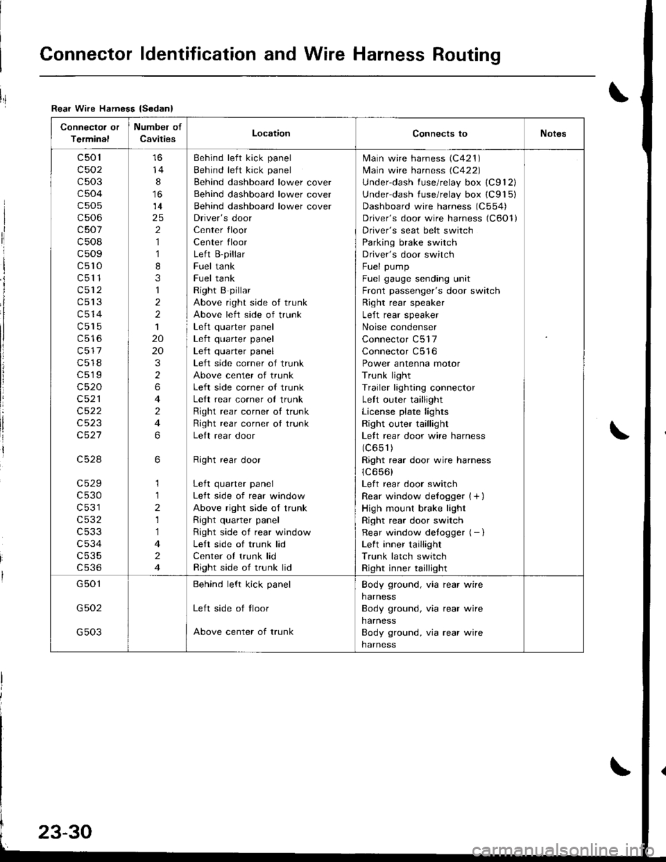
Rear Wire Hamess {Sedan}
I
ri
I
i
I
li
!