1998 HONDA INTEGRA Jack stand
[x] Cancel search: Jack standPage 152 of 1681

/
li
l
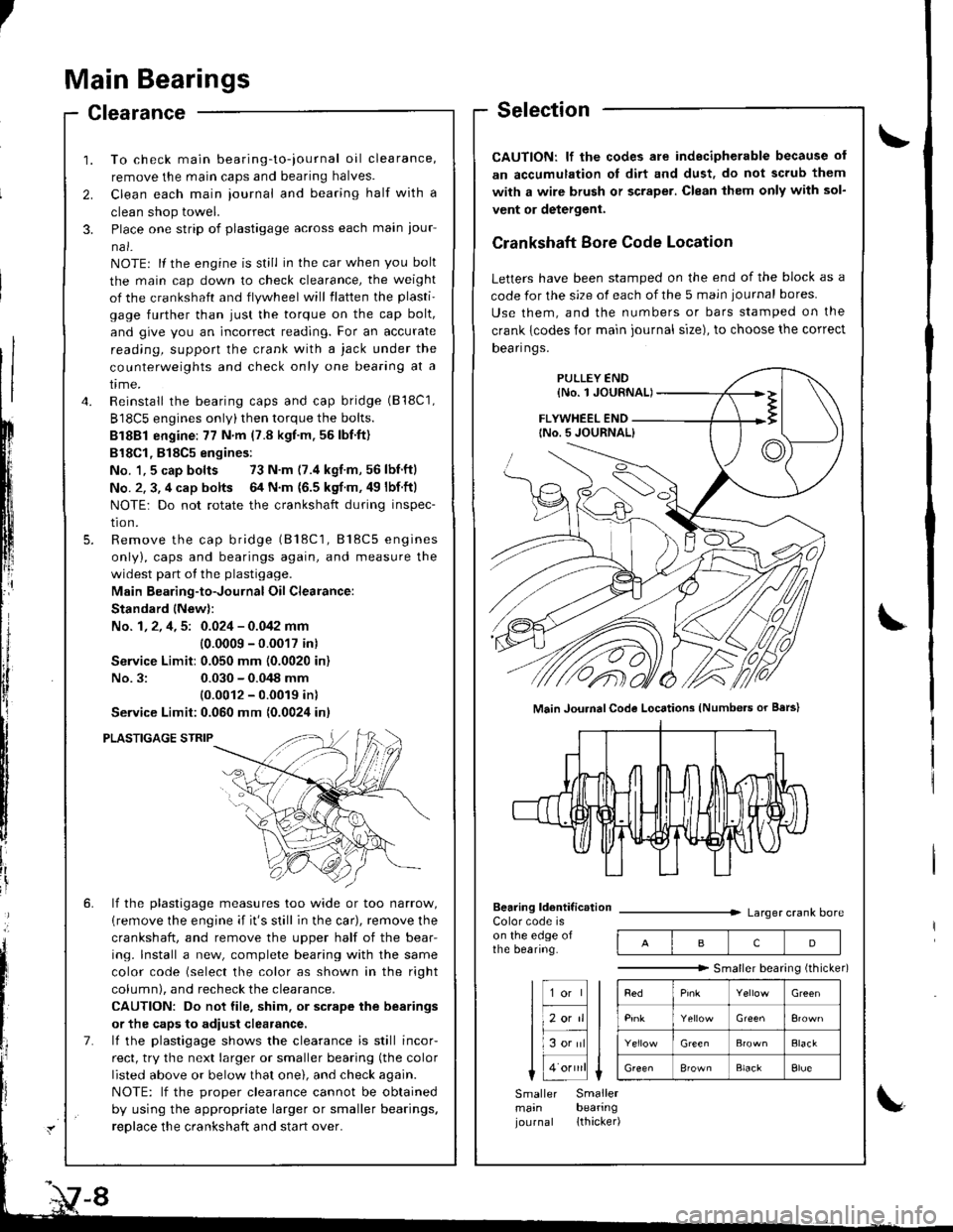
Main Bearings
Clearance
2.
3.
1.
4.
To check main bearing-to-iournal oil clearance,
remove the main caps and bearing halves.
Clean each main iournal and bearing half with a
clean shop towel.
Place one strip of plastigage across each main iour-
na l-
NOTE: lf the engine is still in the car when you bolt
the main cap down to check clearance, the weight
of the crankshaft and flywheel will flatten the plasti'
gage further than just the torque on the cap bolt,
and give you an incorrect reading. For an accurate
reading, support the crank with a jack under the
counterweights and check only one bearing at a
trme.
Reinstall the bearing caps and cap bridge (B18C1,
B18C5 engines only)then torque the bolts.
Bl8Bl engine: 77 N'm (7.8 kgt.m.56lbf.ft)
B18Cl,818C5 engines:
No. 1,5 cap bolts 73 N.m (7.4 kgf.m,56lbnftl
No. 2. 3, 4 cap bolts 64 N.m {6.5 kgf m. 49 lbf ftl
NOTE: Do not rotate the crankshaft during inspec-
tro n.
Remove the cap bridge (818C1, 818C5 engines
only), caps and bearings again, and measure the
widest part of the plastigage.
Main Bearing-to-Journal Oil Clearance:
Standard lNew):
No. 1, 2, 4, 5: 0.024 - 0.042 mm
10.0009 -0.0017 in)
Service Limit:0.050 mm (0.0020 in)
No.3:0.030 - 0.048 mm
10.0012 - 0.0019 inl
Service Limit:0.060 mm {0.0024 inl
PLASTIGAGE STRIP
lf the plastigage measures too wide or too narrow,
{remove the engine if it's still in the car), remove the
crankshaft, and remove the upper half of the bear-
ing. lnstall a new, complete bearing with the same
color code (select the color as shown in the right
column), and recheck the clearance.
CAUTION: Do not file, shim. or scrape the bearings
or the caps to adiust clearance.
lf the plastigage shows the clearance is still incor-
rect, try the next larger or smaller bearing (the color
listed above or below that one), and check again.
NOTE: lf the oroDer clearance cannot be obtained
by using the appropriate larger or smaller bearings.
reolace the crankshaft and start over.
Selection
CAUTION: lf the codes ale indecipherable because of
an accumulation oI dirt and dust, do not scrub them
with a wire bru6h or scraper. Clean lhem only with sol-
vent or detergent.
Crankshaft Bore Code Location
Letters have been stamped on the end of the block as a
code for the size of each of the 5 main iournal bores
Use them, and the numbers or bars stamped on the
crank {codes for main journal size), to choose the correct
Dean nqs,
FLYWHEEL END
Main JouhalCode Locations (Numbe.s or Bars)
Bearing ldentif ic.tionColor code ison the edge ofthe bearing.
Larger crank bore
acD
"""""""" Smallerbearingithicker)
Green
Elack
B'ownBlackElue
Smaller Smallermain bearingjournal lthacker)
Page 290 of 1681

The scan tool indicates Diagnostic Trouble Code (DTC) P0500r A low voltage problem in the Vehicle Speed
Sensor (VSS) circuit.
Intermittent failure, system is OKat this time. Check for ooor con-neciions or loose wires at C112IVSSI and ECM.
ECM CONNECTORS
A (32P)
LGlIBRN/8LK)
c (31Pt
vss{ORN)
Wire side of female terminals
The MIL has been reported on.DTC P0500 is stored.
Probleft veritication:1. Test drive the car.2. Check the vehicle speed withthe scan tool,
ls the correct speed indicated?
Check lor an open in the ECM:1. Turn the ignition switch OFF.2. Block the rear wheels and setthe parking brake.3. Jack up the front of the car andsuppon it with safety stands.4. Turn the ignition switch ON (ll).
5. Block the right front wheeland slowly rotate the left front
6. Measure voltage betweenECM connector terminals C18and A9.
Substitute a known-good ECMand recheck. H symptom/indica-tion goes away, replace tho origi-nalECM.
Does the voltage pulse 0 Vand 5 V or battery voltage?
Check lor a shori in th€ ECM:1. Turn the ignition switch OFF.2. Disconnect the ECM connector C (31P).
3. Turn the ignition switch ON (lli.4. Block the right front wheeland slowly rotate the left front
5. Measure voltage between ECMconnector lerminals C18 andA9.
Substitute a known-good ECMand lecheck. lf symptom/indica-tion goos away. rsplaco the origi-nalECM.
Does the vohage pulse 0 Vand 5 V or battery voltage?
Repair short in the wireb€tween ECM {C18} end VSS,TCM, or cruise control unit.Repeir open in the wirebetween ECM (C18) aod VSS.ff wire is OK, replace the VSS.
ra 17 18 19 20t6 ]t 13r19
LG1{BRN/BLKIvss(ORNI
23563910 1156
12i5r92022 23 2a11 1213 1/tr6ts/zt
25262Aa9,/2724," ,/ ,,:
1 1-85
Page 332 of 1681

1r
;
J
I
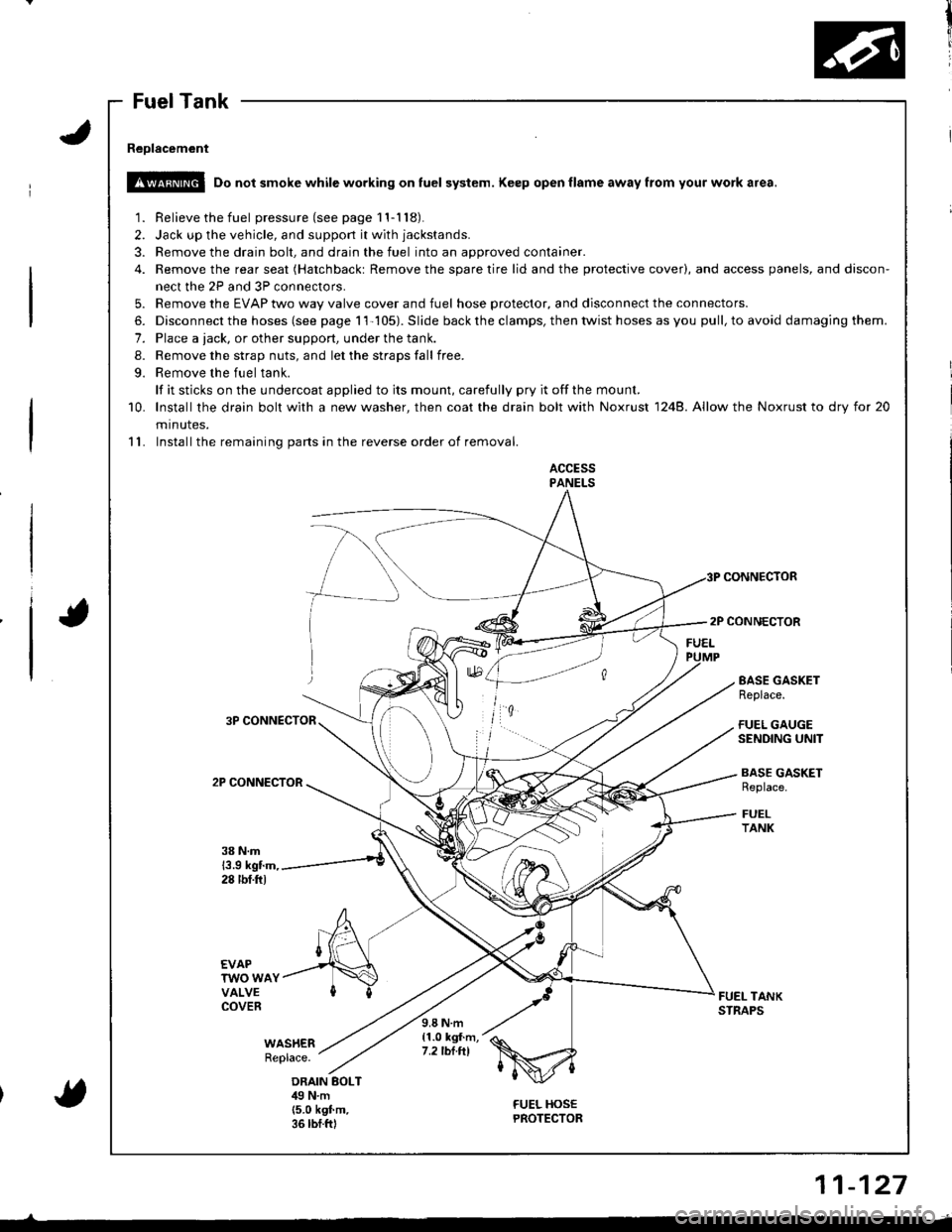
Fuel Tank
Reolacement
!!@ Do not smoke while working on fuel system. Keep open flame away from your work a.ea.
1. Relieve the fuel pressure(seepagell-118).
2. Jack up the vehicle, and support it with jackstands.
3. Remove the drain bolt, and drain the fuel into an approved container.
4. Remove the rear seat (Hatchbackt Remove the spare tire lid and the protective cover), and access panels, and discon-
nect the 2P and 3P connectors.
5. Remove the EVAP two way valve cover and fuel hose protector, and disconnect the connectors.
6. Disconnect the hoses (see page 11-105). Slide back the clamps, then twist hoses as you pull, to avoid damaging them.
7. Place a tack, or other support, under the tank.
8. Remove the strap nuts, and let the straps fall free.
9. Remove the fuel tank.
lf it sticks on the undercoat applied to its mount, carefully pry it offthe mount.
10. lnstallthe drain bolt with a new washer, then coat the drain bolt with Noxrust 1248. Allow the Noxrust to dry tor 20
minutes.
11. Installthe remaining parts in the reverse order of removal.
ACCESSPANELS
CONNECTOR
2P CONNECTOR
3P CONNECTOR
2P CONNECTOR
EASE GASKETReplace.
FUEL GAUGESENDING UNIT
BASE GASKETReplace.
FUELTANK
38 N.m13.9 kgtm,28 tbf.ftl
EVAPTWO WAYVALVECOVERFUEL TANKSTNAPS
WAS}IERReplace.
9.8 N.m{1.0 kgf.m,7.2 tbt.tll
ORAIN BOLTilg N.m(5.0 k9f.m.36 rbf.ftl
FUEL HOSEPROTECTOR{
11-127
Page 353 of 1681

Emission Control System
Check the vacuum when hot:1. Turn the ignition switch OFF.2. Block the rear wheels and setthe parking brake.3. Jack up the front of the vehi-cle and support it with safetystands.4- Start the engine. Hold theengine at 3,000 rpm with noload (in Park or neutral) untilthe radiator fan comes on, thenlet it idle.5. Check for vacuum at the vacuum hose with transmissionin gear (A/T in E position,M/T in 'l st gear) after startingrne engrne.6. Ouickly raise the engine speedto 3,000 rpm.
Evaporative Emission (EVAP) Controls (cont'd)
(From page 1'l 147)Check the EVAP purge controlsolenoid valve:1. Disconnect the 2P connectorfrom the EVAP purge controlsolenoid valve.2. Ouickly raise the engine speedto 3,000 rpm.
{To page 11 149)
tfl'I
Check lor a short in the wire{PCS line}l1. Turn the ignition switch OFF.2. Disconnect ECM connector A(32P).
3. Check for continuity betweenthe EVAP purge control solenoid valve 2P connector termi-nal No. 2 (818C5 engine: No. 1)and body ground.
Check for an open in the wire llclline):1. Turn the ignition switch OFF.2, Disconnect the 2P connectorfrom the EVAP purge controlsolenoid valve.3. Turn the ignition switch ON (ll).
4. At the harness side, measurevo ltage between the EVAPpurge controlsolenoid valve 2Pco n nector terminal No. 1( B 18C5 engine: No. 2) andbody ground.
EVAP PURGE CONTROI SOLENOIDVALVE 2P CONNECTOR IC114)B18C1, Cl8Bl engines: 818C5 engine:
PCSIRED/YEL}
femaleWire side offemaleterminals
YES
IGPl{YEL/BLKI
IGPlIYEL/BLKI
ECM CONNECTOR A {32PIPG1IBLKI
Insp€ct vacuum hose routing.lf OK, replace the EVAP purge
control solenoid valve.
neDair short in the wire betweenthe EVAP purge control solenoidvalve and the ECM lAl5).
Substitute a known-90od ECMand recheck. lI symptom/indica-tion goes away, replace the origi-nal ECM.
Repair open in the wirc betweenEVAP purge control solenoidvalve and PGM-FI main relav fuse.ls there battery voltage?
Check for an open in the wireIPCS linel:1. Turn the ignition switch OFF.2. Reconnect the 2P connector tothe EVAP purge control sole'noid valve.3. Turn the ignition switch ON (ll).
4. Measure voltage betweenECM connector terminals A15and A10.
Bopair open in the wiro betweenthe EVAP purgo control 3olanoidvalvo and the EcM {415).
11-144
(To page 11-149)
Page 735 of 1681

1.Loosely install the
aligning tab facing
two flange nuts,
damper on the frame with
inside, then loosely install
the
the
2.Install the damper fork over the driveshaft and onto
the lower arm. Install the front damper in the
damper fork so the aligning tab is aligned with the
slot in the damper fork.
Loosely install the flange bolt.
Loosely install a new self locking nut with the
flange bolt.
Raise the knuckle with a floor jack until the vehicle
just lifts off the safety stand.
@ The ltoor jack must be securely posi-
tioned or personal iniury may result.
Tighten the flange bolt.
Tighten the self-locking nut.
Tighten the flange nuts on the top of the damper to
3.
FLANGE NUTS10 x'1.25 mm49 N m 15.0 kgt m,36 lbtft)Tighten to this torque in step 8.
4.
5.
6.
7.
8.
the specified torque.
9. lnstall the brake hose mounts with the brake hose
mounting bolts.
ERAKE HOSE MOUNTING BOLT18 x 20 mml
/GS, GsR, Type R Models: \lgr25-- ,22 N.m 12.2 kgt m, 16 lbf.ft)BRAKE HOSE MOUNTING BOLT{8 x 16 mm)22 N.m {2.2 kgl.m, 16lbtft}
FLANGE BOLT
SELF.LOCKING NUT12 x L25 mm64 N.m (6.5 kgt m, 47 lbI.ftl
BOLT10 x 1.25 mm,|:} N.m {4.4 kstm, 32lbtft}
10. Install the front wheel (see page 18-17).
DAMPER
ALIGNING TA8
lnstallation
8-25
Page 750 of 1681

Rear Damper
Lower the rear suspension and position the damper
with the welded nut pointed toward the front of the
vehicle.
DAMPER
2. Loosely install the two flange nuts.
Hatchback:Sedan:
lnstallation
. ',.?7,:..r9\,ir '..
EY
FLANGE NUTS10 x 1.25 mmTighten these nuts in step 7 on the next page.
18-40
3. Install the wheel sensor wire bracket.
NOTE: Be careful when installing the sensors to
avoid twisting wires.
Raise the rear suspension with a floor iack until the
vehicle just lifts off the safety stand.
@ The floor jack must be securely posi-
tionod or personal iniury may result.
5. Install the damper mounting bolt and the flange
bolt, then tighten the bolts.
NOTE: The damper mounting bolt and the flange
bolt should be tightened with the damper under
vehicle load.
FLANGE EOLT10 x 1.25 m.n54 N.m (5.5 kgf m, 40 lbt.ftl
FLANGE BOLT10 x 1-25 mm54 N.m ls.s kgf m, 40 lbtft)
6. Tighten the three wheel sensor wire bracket bolts
{for vehicles with ABS).
9.8 N.m {1.0 kg{.m, 7.2 lbtftlBOLTS
Page 758 of 1681

Inspection and Adiustment
Parking Brake
Inspection
1. Pull the parking btake lever with 196 N
lbf) of force to Jully apply the parking
parking brake lever should be locked
soecified notches.
Lever Locked Notches: 6- l0
{20 kgf, 44
brake. The
within the
Pulled up with 196 N {2O kgf, 44 lbf)
LEVER LOCKED NOTCHES
2, Adjust the parking brake if the lever notches are out
of specification.
Adjustment
NOTE: After rear brake caliper servicing.loosen the park-
ing brake adjusting nut, start the engine, and depress the
brake pedal several times to set the self-adjusting brake
before adiusting the parking brake
1. Raise the rear wheels oIt the ground. and suppon
the car on safety stands.
!!@ ato"t the trort whoels bsfore jacking
up the roal ot tha car'
2. Make sure the parking brake arm on the rear brake
caliDer contacts the brake caliper pin.
19-6
8.
3. Pullthe parking brake lever up one notch'
Remove the rear console {see section 20)'
Tighten the adjusting nut until the rear wheels drag
slightly when turned.
7.
Release the parking brake lever fully, and check that
the rear wheels do not drag when turned. Readjust
if necessary.
Make sure the parking brakes are fully spplied when
the parking brake lever is pulled up fully.
Install the cap onto the parking brake cable end, and
reinstall the rear console.