Page 752 of 1807
F03320F03321F03322
R/B
No.2
Battery
B
W-B
EA
A6
A7
A6 A9 A9 A8
A19
2A 1
ALT
12
2ABS No.1
2RR1
2
6
DLC1
L-WABS ECU
A19
A19
IB6 Y-GABS ECU
4
R/B
No.2
ABS No.1
1
12 2
BatteryR/B No.2
5
12
4
IB5
A21A20
A6
EA
2JZ-GE Engine (NORMAL ABS):
2
11
ABS ECU 6
IB6
A21
RABS Control Relay
Motor
Relay
A7A7 A7 A7A7
A19
A19
A19
A19
IB5 IB5IB5
IB5 IB5 IB5
ABS Actuator
A9
Solenoid
Relay
5
ABS Pump
Motor
P P-LY Y-R B-Y B-R
Y-GP P-LY Y-R B-Y B-R
5
1
5 6
2
8
7
5 58
7
9 4
31
4 11
10
22
21
16SFLRMonitor
SFLH
SFRR
SFRH
SRR
SRH
AST
5
5
5 35
5
5ABS ECU R 2JZ-GTE Engine (SPORT ABS):
W-B
A64 L-W
ALT
2A
B
ABS ActuatorMonitor
A20
A21
A21
A20
A20
A21
IB5
IB5
IB5
IB5
IB5
IB5
IB5 YY
Y-R Y-R
B-Y
B-Y
B-R
B-R
P
P
P-L
P-L
P-B
P-B
R-L
R-L
Y-GY-G
A7
A7
A7
A7
A7
A7
A7
A7
1DLC1
1
1
5
55
55 22
6
66
44
4 88
33
77
9
1011
12
15
14 ABS Solenoid
Relay
SFRH
SFRR
SFLH
SFLR
SRRH
SRRR
SRLH
SRLR
AST
- DIAGNOSTICSANTI-LOCK BRAKE SYSTEM
DI-467
695 Author�: Date�:
1997 SUPRA (RM502U)
WIRING DIAGRAM
Page 755 of 1807
F02626F02643
F02644
R/B
No.2
Battery
B
W-BW-BW-B
EAA6A6 A6
A6
A6 A9 A8 A9 A9A8 A8
A8
A9
IB6
IB6
IB6A19
A19
A19
2A 1
ALT
1 2
2ABS No.1
2RR1
2
6ABS Control Relay
4
3
1 Solenoid
Relay
DLC1 L-BL-B V-W V-WV
V7
8
18ABS ECU
MR
R+
SR
AST
MT 16
9
A19
A19Y-G
G-W 2
13
1
6 5
IB6
IB6 Y-G
G-W 5
3
ABS ActuatorABS ECU 5
4 2
2
L
L-W
Motor
Relay
R/B
No.2
ABS No.1
ALT
1
1
22
Battery
B
R/B No.5
55
5 1
23 4
V-W V-WIB6
IB6 6
2
13
A21
A20
26
A6 A6
ABS Pump MotorEA
MR
R+ 2JZ-GE Engine (NORMAL ABS):
2JZ-GTE Engine (SPORT ABS):
R
5
2
L W-B
A6
131ABS ECU
G-W
G-W 6
IB6
A21
10
MT ABS Motor Relay
V
V R
- DIAGNOSTICSANTI-LOCK BRAKE SYSTEM
DI-461
689 Author�: Date�:
1997 SUPRA (RM502U)
WIRING DIAGRAM
Page 761 of 1807
W02989
IB5
IB5
IB2
IB2
IC2
IC2A19 A21
8 Right Front
Speed Sensor2
1L R
EA3
14 9
198
2 20
110
723
322
109FR+
FR-ABS ECU
5V
FL+
FL-
RR+
RR-
RL+
RL- R
L
W
B
V
LG 1
2
4
5
L
P
3 W
B
V
LG 2
2
2 1
1
1 Left Front
Speed Sensor
Right Rear
Speed Sensor
Left Rear
Speed Sensor
*1
3
*2
A19A21
A19
A21
A19
A21
A18
A20
A18
A20
A18
A20
A18
A20 DI-470
- DIAGNOSTICSANTI-LOCK BRAKE SYSTEM
698 Author�: Date�:
1997 SUPRA (RM502U)
WIRING DIAGRAM
*1: NORMAL ABS (2JZ-GE Engine)
*2: SPORT ABS (2JZ-GTE Engine)
Page 766 of 1807
F03330
Battery
B
R/B No.2
ALT
2222AM1 R/B No.2
WR/B No.1
W
2
IG Switch
J/B No.1ABS ECU
IG1
GND1
GND2 ECU IG
444
513 B-Y
1B1J1J 1K A18A20
213*1
*2
A20
A20 A19
A19212
13 25W-B
W-B W-B W-B
IG
IEW-B
*2
NORMAL ABS (2JZ-GE Engine)
SPORT ABS (2JZ-GTE Engine)*1:
*2:
W
- DIAGNOSTICSANTI-LOCK BRAKE SYSTEM
DI-475
703 Author�: Date�:
1997 SUPRA (RM502U)
DTC 41 IG Power Source Circuit
CIRCUIT DESCRIPTION
This is the power source for the ECU, hence the CPU and the actuators.
DTC No.DTC Detecting ConditionTrouble Area
41Voltage at ECU terminal IG1 is less than 9.5 V for more than
10 sec. while vehicle speed is 3 km/h (1.9 mph) or more.�Battery
�IC regulator
�Open or short in power source circuit
Fail safe function:
If trouble occurs in the power source circuit, the ECU cuts off current to the ABS solenoid relay and prohibits
ABS control.
WIRING DIAGRAM
DI4VF-01
Page 769 of 1807
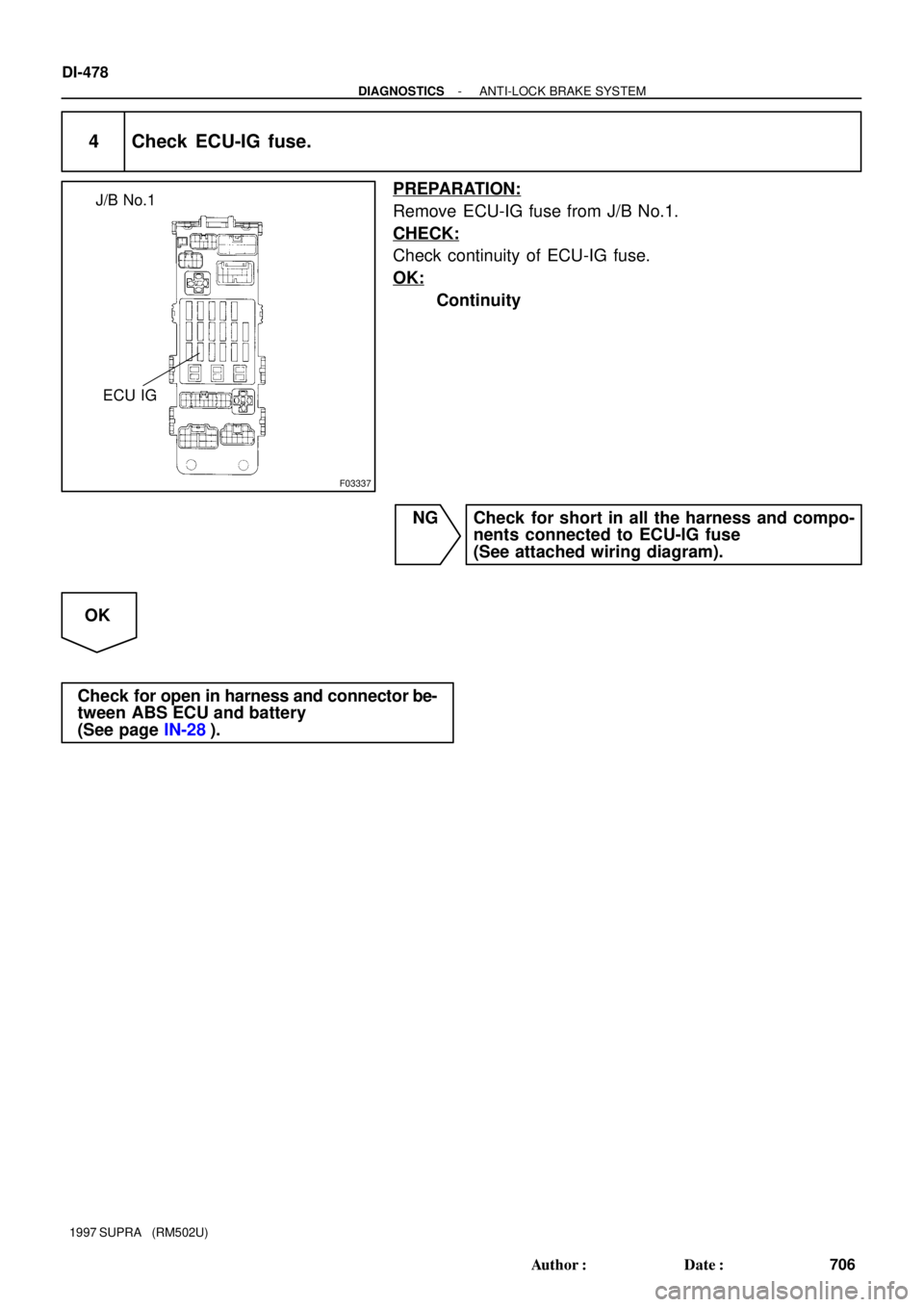
F03337
ECU IG J/B No.1
DI-478
- DIAGNOSTICSANTI-LOCK BRAKE SYSTEM
706 Author�: Date�:
1997 SUPRA (RM502U)
4 Check ECU-IG fuse.
PREPARATION:
Remove ECU-IG fuse from J/B No.1.
CHECK:
Check continuity of ECU-IG fuse.
OK:
Continuity
NG Check for short in all the harness and compo-
nents connected to ECU-IG fuse
(See attached wiring diagram).
OK
Check for open in harness and connector be-
tween ABS ECU and battery
(See page IN-28).
Page 771 of 1807
F03338
Deceleration sensor
3
5
1
2
A23
A23
A23
A23B
W-B
W
R
G
W-B
IG IEA20
A20
A20
A20
3
16
4
17VGS
GL2
GL1
GGNDABS ECU DI-480
- DIAGNOSTICSANTI-LOCK BRAKE SYSTEM
708 Author�: Date�:
1997 SUPRA (RM502U)
DTC 44 Deceleration Sensor Circuit
(SPORT ABS (2JZ-GTE Engine) only)
CIRCUIT DESCRIPTION
This sensor detects deceleration on the vehicle. The sensor signal is used in ABS control. If the sensor func-
tions abnormally, the ABS warning light comes on but the ABS still operates.
DTC No.DTC Detecting ConditionTrouble Area
44
Either of the following (1), (2) or (3) is detected:
(1) IG switch ON and output voltage of GL1 or GL2 remains
0.5 V or less or 4.5 V or more for more than 1.2 sec.
(2) At vehicle speed of 0 km/h, outputs of GL1 and GL2 re-
mains abnormally different for 60 sec. or more
(3) IG switch ON and VGS � 4.4 V, VGS � 5.5 V continues
for 1.2 sec. or more.
�Deceleration sensor
�Open or short in deceleration sensor circuit
WIRING DIAGRAM
DI4VH-01
Page 773 of 1807
F03341
R/B No.2J/B No.1Stop Light
SwitchABS ECU
125
Light
Failure
Sensor
Stop LightJ/B
No.11
10IH
IC
A18 A22 *1*2
G-WG-W
G-W1
2 W STOP
210
1B 1I W-LPOWER
22 W
2
2A
ALTR/B No.2
B
Battery
NORMAL ABS (2JZ-GE Engine)
SPORT ABS (2JS-GTE Engine)
*1:
*2:
1
DI-482
- DIAGNOSTICSANTI-LOCK BRAKE SYSTEM
710 Author�: Date�:
1997 SUPRA (RM502U)
DTC 49 Stop Light Switch Circuit
CIRCUIT DESCRIPTION
This stop light switch senses whether the brake pedal is depressed or released, and sends a signal to the
ECU.
DTC No.DTC Detecting ConditionTrouble Area
491.2 - 1.7 V of STP voltage is continued for 0.3 sec. or more.�Open in stop light circuit
WIRING DIAGRAM
INSPECTION PROCEDURE
1 Check operation of stop light.
CHECK:
Check that stop light lights up when brake pedal is depressed and turns off when brake pedal is released.
NG Replace stop light bulb.
OK
DI4VI-01
Page 775 of 1807
DI-484
- DIAGNOSTICSANTI-LOCK BRAKE SYSTEM
712 Author�: Date�:
1997 SUPRA (RM502U)
DTC 51 ABS Pump Motor Lock
CIRCUIT DESCRIPTION
DTC No.DTC Detecting ConditionTrouble Area
51Pump motor is not operating normally during initial check.�ABS pump motor
Fail safe function:
If trouble occurs in the ABS pump motor, the ECU cuts off the current to the ABS solenoid relay and prohibits
ABS control.
WIRING DIAGRAM
See page DI-460.
INSPECTION PROCEDURE
See inspection of ABS actuator (See page BR-66 or BR-66).
DI4VJ-01