Page 89 of 1807
27 SUPRAÐNEW FEATURES
Construction
The helical gear type torque±sensing LSD consists of a differential case, 9 planet gears, 2 side gears and 4 thrust
washers.
Planet gears mesh with one another as a pair, and each gear of the pair meshes with the side gear on its right or left
side.
The planet gears are supported by the hole that is provided in the differential case. They are constructed so that they
revolve while rotating over the side gear.
Operation
1) Straight±Ahead Operation
Since side gears (left and right) and planet gears are rotating together with the differential case as a unit when the
vehicle is running straight±forward, the driving force is transmitted from the ring gear to the differential case, planet
gears and side gears.
Page 90 of 1807

28SUPRAÐNEW FEATURES
2) Cornering
Supposing that the differential case is not moving, rotating the left side gear counterclockwise, causes planet gear
A (which meshes with the left side gear) to rotate clockwise.
Furthermore, planet gear B, which is paired with planet gear A, rotates counterclockwise, causing the right side gear
(which meshes with planet gear B) to rotate clockwise.
Therefore the left and right side gears rotate in the opposite direction each other, thus accomplishing a motion
differential.
3) Limited Slip Differential Operation
Limited slip is accomplished primarily b the friction that is generated between the planet gear's tooth tips and the
differential case's inner wall, and the friction that is generated between the side gear end face and the thrust washer.
The principle of limited slip enables the resultant reaction force F1 (which is created by the meshing reaction of the
planet gear and the side gear and the meshing reaction of the planet gears themselves) to push the planet gear in the
direction of the differential case in proportion to the input torque.
Due to the reaction force F1, the friction force u F2 (which is generated between the side gear end face and the thrust
washer) applies a force to cancel out the rotational difference between the side gears themselves as well as between
the side gear and the differential case.
Page 103 of 1807

22SUPRAÐOUTLINE OF NEW FEATURES
SUPRA
OUTLINE NEW FEATURES
The Supra, which represents Toyota's advanced automotive technology, has earned a reputation as a truly luxurious
sports car. The following changes have been made for the 1997 model year.
1. Model Line±Up
�The JZA80L±ALPVZA model has been discontinued.
�The JZA80L±ALFVZA and JZA80L±AJFVZA models have been added.
2. Exterior Design
�The multi±reflector type headlights are adopted.
�The design of the turn signal light, front bumper and rear combination light has been changed.
3. Interior Equipment
The front seats have been changed from the separate±headrest type seats of the '96 model to the integrated headrest
type seats without changing their basic design.
4. 2JZ±GTE Engine
An aluminum radiator core is adopted for weight reduction.
5. Differential
�A differential gear ratio has been changed on he 2JZ±GE engine model.
�A helical gear type torque±sensing LSD is available as an option on the 2JZ±GE engine model and 2JZ±GTE engine
with automatic transmission model.
6. Drive Shaft
An outboard joint of drive shaft has been changed from cross±groove type CVJ (Constant±Velocity Joint) to Rzeppa
type CVJ on the 2JZ±GE engine model.
7. Brakes
�A master cylinder diameter has been changed on the 2JZ±GTE engine model.
�An ABS has been changed to the 2±position solenoid valve type actuator.
Page 105 of 1807

124APPENDIXÐSUPRA
� SUPRA
Item AreaU.S.A..Body Type2±Door Liftback (Standard Roof)2±Door Liftback (Sport Roof)Vehicle GradeÐModel CodeJZA80L±ALMVFAJZA80L±ALPVFAJZA80L±AJMVFAJZA80L±AJPVFALength mm (in.)4515 (177.8)uuu
OverallWidth mm (in.)1810 (71.3)uuuOverallHeight* mm (in.)1275 (50.2)uuuWheel Base mm (in.)2550 (100.4)uuu
TreadFront mm (in.)1520 (59.8)uuuTreadRear mm (in.)1525 (60.0)uuu
Effective Head RoomFront mm (in.)953.2 (37.5)u946.8 (37.3)uEffective Head RoomRear mm (in.)834.5 (32.9)uuu
sEffective Leg RoomFront mm (in.)1117.0 (44.0)uuu
ghtsEffective Leg RoomRear mm (in.)605.1 (23.8)uuu
We i g
h
Shoulder RoomFront mm (in.)1376.3 (54.2)uuu
icle WShoulder RoomRear mm (in.)1113.2 (43.8)uuu
VehicOverhangFront mm (in.)950 (37.4)uuu
s & VeOverhangRear mm (in.)1015 (40.0)uuu
sions
&Min. Running Ground Clearance mm (in.)120 (4.7)uuu
mensioAngle of Approach degrees13uuu
DimeAngle of Departure degrees17uuu
ajor DFront kg (lb)762 (1680)778 (1715)773 (1705)789 (1740)MajoCurb WeightRear kg (lb)694 (1530)703 (1550)710 (1565)719 (1585)MCurb WeightTotal kg (lb)1456 (3210)1481 (3265)1483 (3270)1508 (3325)Front kg (lb)937 (2065)uuuGross Vehicle WeightRear kg (lb)1002 (2210)uuuGross Vehicle WeightTotal kg (lb)1939 (4275)uuuFuel Tank Capacity l (U.S. gal., Imp. gal.)70 (18.5, 15.4)uuuLuggage Compartment Capacity m3 (cu. ft.)ÐÐÐÐMax. Speed km/h (mph)240 (150)uuuMax. Cruising Speed km/h (mph)193 (120)uuu
Acceleration0 to 100 km/h sec.6.87.46.87.4
ceAcceleration0 to 400 m sec.15.215.715.215.7
mance1st Gear km/h (mph)54 (34)61 (38)54 (34)61 (38)
rform
a
Max Permissible Speed2nd Gear km/h (mph)94 (58)112 (70)94 (58)112 (70)PerfoMax. Permissible Speed3rd Gear km/h (mph)139 (86)Ð139 (86)ÐP4the Gear km/h (mph)ÐÐÐÐTurning DiameterWall to Wall m (ft.)11.5 (38)uuuTurning Diameter(Outside Front)Curb to Curb m (ft.)10.9 (36)uuuEngine Type2JZ±GEuuuValve Mechanism24±Valve, DOHCuuuBore x Stroke mm (in.)86.0 x 86.0 (3.39 x 3.39)uuu
eDisplacement cm3 (cu. in..)2997 (182.9)uuu
ngineCompression Ratio10.0 : 1uuuEngCarburetor TypeSFIuuuResearch Octane No. RON96uuuMax. Output (SAE±NET) kW/rpm (HP @ rpm)164/5800 (220 @ 5800)uuuMax. Torque (SAE±NET) N.m/rpm (lb±ft @ rpm)285/4800 (210 @ 4800)uuu
alBattery Capacity (20HR) Voltage & Amp. hr.12±52uuu
ginectric a lGenerator Output Watts1080uuuEnginElectrStarter Output kW1.4uuuClutch TypeDry, Single PlateÐDry, Single PlateÐTransmission TypeW58A340EW58A340EIn First3.2852.8043.2852.804In Second1.8941.5311.8941.531In Third1.2751.0001.2751.000Transmission Gear RatioIn Fourth1.0000.7051.0000.705Transmission Gear RatioIn Fifth0.783Ð0.783ÐIn SixthÐÐÐÐIn Reverse3.7682.3933.7682.393Differential Gear Ratio4.083uuuDifferential Gear Size mm (in.)205 (8.07)uuu
ssisBrake TypeFrontVentilated Discuuu
ChassBrake TypeRearVentilated DiscuuuChParking Brake TypeDual±ServouuuBrake Booster Type and Style in.Tandem 8º + 9ºuuuProportioning Valve TypeP & B Valveuuu
Suspension TypeFrontDouble WishboneuuuSuspension TypeRearDouble Wishboneuuu
Stabilizer BarFrontSTDuuuStabilizer BarRearSTDuuuSteering Gear TypeRack & PinionuuuSteering Gear Ratio (Overall)17.5 : 1uuuPower Steering TypeIntegral Typeuuu* : Unladen Vehicle, *1 : Electrically Controlled Transmission with an intelligent sporty control
Page 121 of 1807

AC0QA-01
AC-22
- AIR CONDITIONINGREFRIGERANT LINE
2170 Author�: Date�:
1997 SUPRA (RM502U)
REPLACEMENT
1. DISCHARGE REFRIGERANT FROM REFRIGERATION SYSTEM
2. REPLACE FAULTY TUBE OR HOSE
NOTICE:
Cap the open fittings immediately to keep moisture or dirt out of the system.
3. TIGHTEN JOINT OF BOLT OR NUT AT SPECIFIED TORQUE
NOTICE:
Connections should not be torqued tighter than the specified torqued.
Part tightenedN´mkgf´cmft´lbf
Receiver x Liquid tube5.45548 in.´lbf
Condencer x Discharge hose101007
Condenser x Liquid tube101007
Compressor x Discharge hose101007
Compressor x Suction hose101007
Evaporator x Expansion valve5.45548 in.´lbf
A/C unit x Liquidand suction tube101007
Discharge lines101007
Liquid lines101007
Suction lines101007
4. EVACUATE AIR IN REFRIGERATION SYSTEM AND CHARGEWITH REFRIGERANT
Specified amount: 700 ± 50 g (24.96 ± 1.76 oz.)
5. INSPECT FOR LEAKAGE OF REFRIGERANT
Using a gas leak detector, check for leakage of refrigerant.
6. INSPECT AIR CONDITIONING OPERATION
Page 125 of 1807

N08379
N08536
N09037
I03520
AC-26
- AIR CONDITIONINGAIR CONDITIONING UNIT
2174 Author�: Date�:
1997 SUPRA (RM502U)
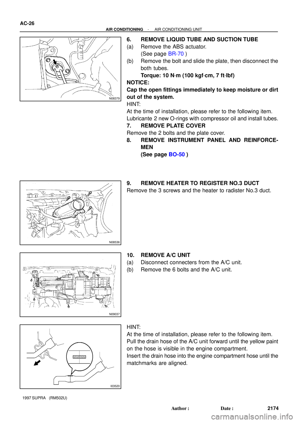
6. REMOVE LIQUID TUBE AND SUCTION TUBE
(a) Remove the ABS actuator.
(See page BR-70)
(b) Remove the bolt and slide the plate, then disconnect the
both tubes.
Torque: 10 N´m (100 kgf´cm, 7 ft´lbf)
NOTICE:
Cap the open fittings immediately to keep moisture or dirt
out of the system.
HINT:
At the time of installation, please refer to the following item.
Lubricante 2 new O-rings with compressor oil and install tubes.
7. REMOVE PLATE COVER
Remove the 2 bolts and the plate cover.
8. REMOVE INSTRUMENT PANEL AND REINFORCE-
MEN
(See page BO-50)
9. REMOVE HEATER TO REGISTER NO.3 DUCT
Remove the 3 screws and the heater to radister No.3 duct.
10. REMOVE A/C UNIT
(a) Disconnect connecters from the A/C unit.
(b) Remove the 6 bolts and the A/C unit.
HINT:
At the time of installation, please refer to the following item.
Pull the drain hose of the A/C unit forward until the yellow paint
on the hose is visible in the engine compartment.
Insert the drain hose into the engine compartment hose until the
matchmarks are aligned.
Page 126 of 1807

AC0QD-02
N08381
N08398
Expansion valve
N08384
- AIR CONDITIONINGAIR CONDITIONING UNIT
AC-27
2175 Author�: Date�:
1997 SUPRA (RM502U)
DISASSEMBLY
1. REMOVE AIR INLET SERVOMOTOR
(a) Disconnect the connector.
(b) Disconnect the control link.
(c) Remove the 3 screws and the air inlet servomotor.
2. REMOVE BLOWER MOTOR CONTROL RELAY
(a) Disconnect the connector.
(b) Remove the 3 screws and the blower motor control relay.
3. REMOVE BLOWER MOTER
(a) Disconnect the connector.
(b) Remove the 3 screws and blower motor.
4. REMOVE EVAPORATOR
(a) Remove the wire harness.
(b) Remove the foot air duct.
(c) Remove the A/C unit block joint.
(d) Remove the 6 screws and down and the lower cover.
(e) Remove the 4 screws and the evaporator cover.
(f) Pull out the evaporator.
HINT:
At the time of reassembly, please refer to the following item.
If the evaporator is replaced, add compressor oil to compressor.
Add 40cc (1.4 fl.oz)
Compressor oil: ND-OIL 8 or equivalent
(g) Pull out the evaporator temp.sensor from the evaporator.
(h) Using a hexagon wrench, remove the 2 bolts and sepa-
rate the evaporator and expansion valve.
Torque: 5.4 N´m (55 kgf´cm, 48 in.´lbf)
HINT:
At the time of reassembly, please refer to the following item.
Lubricate 4 new O-rings with compressor oil and install the
tubes.
5. REMOVE AIR MIX SERVOMOTOR
(a) Remove the defroster duct.
(b) Remove the 3 screws and the water valve cover.
(c) Disconnect the connector.
(d) Disconnect the control link.
(e) Remove the screws and the air mix servomotor.
Page 131 of 1807
AC0943
SST
AC0QJ-01
AC0944
SST
AC0945
SST
AC0946
Shim
Pressure
Plate
AC0947
SST AC-34
- AIR CONDITIONINGCOMPRESSOR AND MAGNETIC CLUTCH
2182 Author�: Date�:
1997 SUPRA (RM502U)
DISASSEMBLY
1. REMOVE PRESSURE PLATE
(a) Using SST and a socket wrench, remove the shaft bolt.
SST 07112-76060
Torque: 14 N´m (140 kgf´cm, 10 ft´lbf)
(b) Install SST on the pressure palate.
SST 07112-66040
(c) Using SST and socket wrench, remove the pressure
plate.
SST 07112-66040, 07112-76060
(d) Remove the shims from the pressure palate.
2. REMOVE ROTOR
(a) Using SST, remove the snap ring.
SST 07114-84020