Page 689 of 1807

VSV for Exhaust
Bypass Valve
Actuator
(for Exhaust
Bypass Valve)
VSV for Intake Air Control Valve
Actuator (for Intake")
S03236
VSV for Exhaust Gas Control Valve
Actuator (for Exhaust Gas Control Valve)
VSV for Exhaust
Bypass Valve
Actuator
(for Exhaust
Bypass Valve)
VSV for Intake Air Control Valve
Actuator (for Intake Air Control Valve) Exhaust Manifold
Intake Manifold CAC Air Bypass Valve Actuator
(for Waste Gate Valve)Air
Cleaner VSV for Waste
Gate Valve
Waste Gate
Valve
ECM
DI-274
- DIAGNOSTICSENGINE (2JZ-GTE)
502 Author�: Date�:
1997 SUPRA (RM502U)
DTC P1512 Boost Pressure High Malfunction
CIRCUIT DESCRIPTION
To control maximum turbocharging pressure the turbocharger system includes a waste gate valve or exhaust
bypass valve controlled by an actuator. The actuator is controlled by the manifold pressure which is duty
controlled by the VSV based on signals from the ECM.
If the ECM detects the below diagnosis conditions, it operates the fail safe function in which the ECM stops
fuel injection.
DTC No.DTC Detecting ConditionTrouble Area
P1512
Under the following conditions (a), (b) and (c):
(a) After the engine is warmed up
(b) Engine rotation speed 3,400 rpm or less
(c) Under the condition with +740 mmHg or more of intake pipe
pressure
(2 trip detection logic)
�Actuator (for waste gate valve and exhaust bypass valve)
�Short in VSV for waste gate valve and exhaust bypass valve
circuit
�ECM
DI4TJ-01
Page 724 of 1807
FI6897
Pressure
Regulator
From Fuel Tank To
Fuel
Tank
(Return) Intake
Manifold ECMVSV
S03472
Battery
B
EB
W-BEFI No.1
R/B
No.2
1
2A2
B-W
222
2
EFI Relay
R/B
No.2
21 5
3B-R5
EA2
B-Y
EA18
VSV for Fuel
Pressure Control B-R1
2W-L73
B
GR24
AECM
FPU
E01
B+
M-REL
- DIAGNOSTICSENGINE (2JZ-GTE)
DI-309
537 Author�: Date�:
1997 SUPRA (RM502U)
Fuel Pressure Control Circuit
CIRCUIT DESCRIPTION
The ECM turns on a VSV (Vacuum Switching Valve) to draw the
air into the diaphragm chamber of the pressure regulator if it de-
tects that the temperature of the engine coolant is too high dur-
ing engine staring.
The air drawn into the chamber increases the fuel pressure to
prevent fuel vapor lock at high engine temperature in order to
help the engine start when it is warm.
Fuel pressure control ends approx. 120 sec. after the engine is
started.
WIRING DIAGRAM
DI4TV-01
Page 725 of 1807
A00732
ON
E
Air Filter
E
G VSV: ON
VSV: OFF
DI-310
- DIAGNOSTICSENGINE (2JZ-GTE)
538 Author�: Date�:
1997 SUPRA (RM502U)
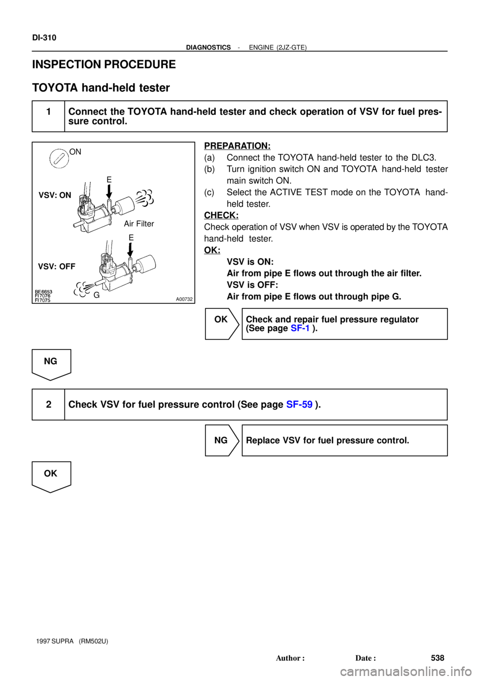
INSPECTION PROCEDURE
TOYOTA hand-held tester
1 Connect the TOYOTA hand-held tester and check operation of VSV for fuel pres-
sure control.
PREPARATION:
(a) Connect the TOYOTA hand-held tester to the DLC3.
(b) Turn ignition switch ON and TOYOTA hand-held tester
main switch ON.
(c) Select the ACTIVE TEST mode on the TOYOTA hand-
held tester.
CHECK:
Check operation of VSV when VSV is operated by the TOYOTA
hand-held tester.
OK:
VSV is ON:
Air from pipe E flows out through the air filter.
VSV is OFF:
Air from pipe E flows out through pipe G.
OK Check and repair fuel pressure regulator
(See page SF-1).
NG
2 Check VSV for fuel pressure control (See page SF-59).
NG Replace VSV for fuel pressure control.
OK
Page 726 of 1807
A00733
ON
Check Harness A
B73
FPU(+)
- DIAGNOSTICSENGINE (2JZ-GTE)
DI-31 1
539 Author�: Date�:
1997 SUPRA (RM502U)
3 Check for open and short in harness and connector between EFI main relay
(Marking: EFI MAIN) and ECM (See page IN-28).
NG Repair or replace harness or connector.
OK
Check and replace ECM (See page IN-28).
OBDII scan tool (excluding TOYOTA hand-held tester)
1 Check VSV for fuel pressure control (See page SF-59).
NG Replace VSV for fuel pressure control.
OK
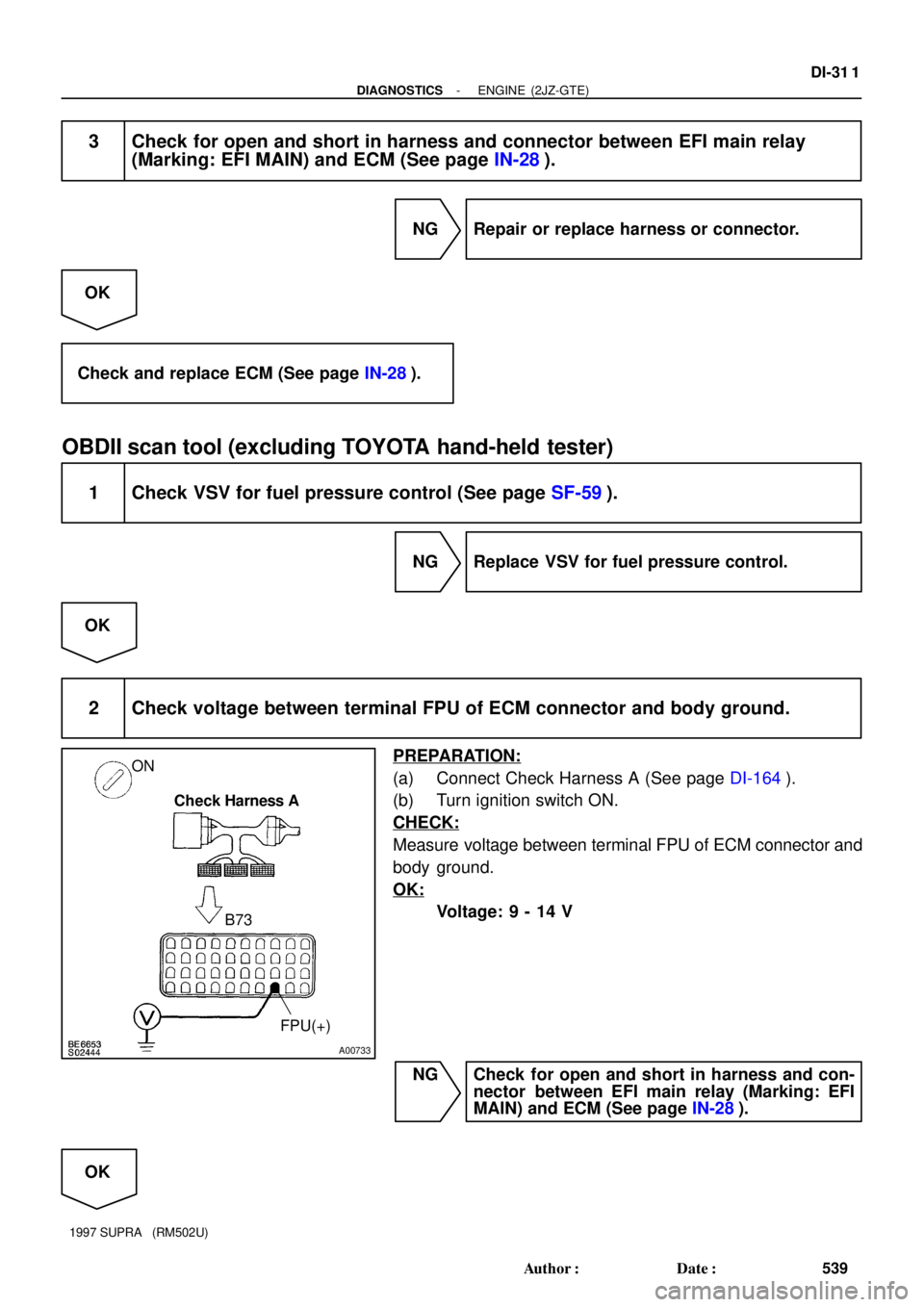
2 Check voltage between terminal FPU of ECM connector and body ground.
PREPARATION:
(a) Connect Check Harness A (See page DI-164).
(b) Turn ignition switch ON.
CHECK:
Measure voltage between terminal FPU of ECM connector and
body ground.
OK:
Voltage: 9 - 14 V
NG Check for open and short in harness and con-
nector between EFI main relay (Marking: EFI
MAIN) and ECM (See page IN-28).
OK
Page 727 of 1807
DI-312
- DIAGNOSTICSENGINE (2JZ-GTE)
540 Author�: Date�:
1997 SUPRA (RM502U)
3 Check fuel pressure regulator (See page SF-1).
NG Repair or replace.
OK
Check and replace ECM (See page IN-28).
Page 1025 of 1807
![TOYOTA SUPRA 1997 Service Repair Manual Position of Parts in Engine Compartment
[2JZ-GTE]
R 1 Radiator Fan Motor No.1
R 2 Radiator Fan Relay No.1
R 3 Radiator Fan Relay No.2
R20 Radiator Fan Motor No.2
S 1 SFI Resistor
S 2 Starter
S 3 Start](/manual-img/14/57469/w960_57469-1024.png "TOYOTA SUPRA 1997 Service Repair Manual Position of Parts in Engine Compartment
[2JZ-GTE]
R 1 Radiator Fan Motor No.1
R 2 Radiator Fan Relay No.1
R 3 Radiator Fan Relay No.2
R20 Radiator Fan Motor No.2
S 1 SFI Resistor
S 2 Starter
S 3 Start")
Position of Parts in Engine Compartment
[2JZ-GTE]
R 1 Radiator Fan Motor No.1
R 2 Radiator Fan Relay No.1
R 3 Radiator Fan Relay No.2
R20 Radiator Fan Motor No.2
S 1 SFI Resistor
S 2 Starter
S 3 Starter
S 5 Sub Throttle Position Sensor
S18 Sub Throttle Valve Motor
T 1 Theft Deterrent Horn
T 2 Throttle Position Sensor
T14 Turbo Pressure Sensor
V 2 VSV (EGR)
V 3 VSV (EVAP)
V 4 VSV (Exhaust Bypass Valve)
V 5 VSV (Exhaust Gas Control Valve)
V 6 VSV (Fuel Pressure Up)
V 7 VSV (Intake Air Control Valve)
V 8 VSV (Waste Gate Valve)
V10 Vehicle Speed Sensor No.1 (Combination Meter)
V11 Vehicle Speed Sensor No.2 (Electronically
Controlled Transmission)
W 1 Washer Motor I 1 Idle AIr Control Valve
I 2 Igniter
I 3 Igniter
I 6 Ignition Coil No.1
I 7 Ignition Coil No.2
I 8 Ignition Coil No.3
I 9 Ignition Coil No.4
I10 Ignition Coil No.5
I11 Ignition Coil No.6
I12 Injector No.1
I13 Injector No.2
I14 Injector No.3
I15 Injector No.4
I16 Injector No.5
I17 Injector No.6
K 1 Knock Sensor (on Front Side)
K 2 Knock Sensor (on Rear Side)
M 1 Mass Air Flow Meter
N 1 Noise Filter
O 1 O/D Direct Clutch Speed Sensor
O 2 Oil Pressure SW
P 1 PPS Solenoid
P 2 Park/Neutral Position SW, Back-Up Light SW and
A/T Indicator Light SW (A/T)
P13 Parking Light LH
25
G
Page 1027 of 1807
![TOYOTA SUPRA 1997 Service Repair Manual 27
G
Position of Parts in Engine Compartment
[2JZ-GE]
O 2 Oil Pressure SW
P 1 PPS Solenoid
P 2 Park/Neutral Position SW, Back-Up Light SW and
A/T Indicator Light SW (A/T)
P 3 Power Steering Pressure S](/manual-img/14/57469/w960_57469-1026.png "TOYOTA SUPRA 1997 Service Repair Manual 27
G
Position of Parts in Engine Compartment
[2JZ-GE]
O 2 Oil Pressure SW
P 1 PPS Solenoid
P 2 Park/Neutral Position SW, Back-Up Light SW and
A/T Indicator Light SW (A/T)
P 3 Power Steering Pressure S")
27
G
Position of Parts in Engine Compartment
[2JZ-GE]
O 2 Oil Pressure SW
P 1 PPS Solenoid
P 2 Park/Neutral Position SW, Back-Up Light SW and
A/T Indicator Light SW (A/T)
P 3 Power Steering Pressure SW
P13 Parking Light LH
S 2 Starter
S 3 Starter
T 1 Theft Deterrent Horn
T 2 Throttle Position Sensor
V 1 VSV (ACIS)
V 2 VSV (EGR)
V 3 VSV (EVAP)
V 6 VSV (Fuel Pressure Up)
V10 Vehicle Speed Sensor No.1 (Combination Meter)
V11 Vehicle Speed Sensor No.2 (Electronically
Controlled Transmission)
W 1 Washer Motor H 1 Headlight Hi LH
H 2 Headlight Hi RH
H 3 Headlight Lo LH
H 4 Headlight Lo RH
H 8 Horn LH
H 9 Horn RH
I 1 Idle Air Control Valve
I 4 Igniter
I 5 Ignition Coil
I 12 Injector No.1
I 13 Injector No.2
I 14 Injector No.3
I 15 Injector No.4
I 16 Injector No.5
I 17 Injector No.6
K 1 Knock Sensor (on Front Side)
K 2 Knock Sensor (on Rear Side)
M 1 Mass Air Flow Meter
M 2 Main Heated Oxygen Sensor (Bank 1 Sensor 1)
M 3 Main Heated Oxygen Sensor (Bank 2 Sensor 1)
N 1 Noise Filter
Page 1075 of 1807

2 1
2 1E16 E1 1
B 40 B38 B45 B66 B28 B62 32512 3
1E2 PIM VC B- R B- R
W- B
L- R W- B
BR
BR
B- R
B- R
B- YBR Y- RP- L G- R G- B
B- R B- R
W- B
B- Y
L- R
VSV1 VSV3 THA VG E2G PM12 1
B 46
BR- Y
THG TURBO PRESSURE SENSOR
MASS AIR FLOW METER M 1T14
ENGINE CONTROL MODULE
V 4
VSV (
EXH AUST
BYPASS VALVE)
E 1
EGR GAS TEMP. SENSOR
A E 9 , E10B
V 7
VSV (
INTAKE AIR
CO NTROL VA LV E)
E1 0E10
B- R
4 THA VG E2E2G B- R
B- R
B- R
+B
B 47 B72 B71 B48 B73 B60 B39
1 2
1 2
1 2
E11 E13 E10 E14IJ1 20IC1 12 IC19IC110
IC1 4IJ2 5IJ214 IJ24
24
4
B- R
B- R
B- RR- L
BR
B- R B- R B- RBR
G- Y L- W
W- LW B- L BR- W
R- L R- L BR- W
R- L BR- W B- R B- R B- R
B- R
B- R
B- RB- R
B- R
B- R W
21 313 OXS HTS HT1 OX1 FPU VSV4 VSV2
(
SHIELDED) (
SHIELDED)
(
SHIELDED) (
SH I ELDED) (
SHIELDED)
(
SHIELDED)
HEATED OXYGEN
SENSOR (
BANK 1
SENSOR 2)
HEATED OXYGEN SENSOR
(
BANK 1 SENSOR 1)
H11
H 5
(
SHIELDED) VSV (
FUEL
PRESSURE UP)
VSV (
WASTE
GATE VALVE)
VSV (
EXHAUST
GAS CONTROL VALVE) V 6
V 8
V 5
11B 50 B49 KNK1 KNK2
W W (
SHIELDED)
KNOCK SENSOR
(
ON REAR SIDE) KNOCK SENSOR
(
ON FRONT SIDE)
K 2
(
SHIELDED) K 1
(
SHIELDED) E14
W- B
W- B
+B E HT OX
E1 +B HT OX
74
ENGINE CONTROL (2JZ-GTE)
 Intake
Manifold ECMVSV
S03472
Battery
B
EB
W-BEFI No.1
R/B
No.2
1
2A2
B-W
222
2
EFI Relay
R/B
No.2
21 5
3B-R5
EA2
B-Y
EA18
VSV for Fuel
P")