Page 174 of 1807

6. INSPECT DOOR COURTESY SWITCH CONTINUITY
(See page BE-28")
Z07503
Wire Harness Side
Z09181
34
2 143
12 BE-18
- BODY ELECTRICALHEADLIGHT AND TAILLIGHT SYSTEM
1996 Author�: Date�:
1997 SUPRA (RM502U)
6. INSPECT DOOR COURTESY SWITCH CONTINUITY
(See page BE-28)
7. CANADA models only:
INSPECT D.R.L. MAIN RELAY CIRCUIT
Disconnect the connector from relay and inspect the connector
on wire harness side, as shown.
Tester connectionConditionSpecified condition
5 - GroundHeadlight dimmer switch position Low beam or
high beamNo continuity
5 - GroundHeadlight dimmer switch position FlashContinuity
8 - GroundParking brake switch position OFFNo continuity
8 - GroundParking brake switch position ONContinuity
16 - GroundHeadlight dimmer switch position Low beamNo continuity
16 - GroundHeadlight dimmer switch position Flash or High
beamContinuity
13 - GroundConstantContinuity
18 - GroundConstantContinuity
2 - GroundIgnition switch position LOCK or ACCNo voltage
2 - GroundIgnition switch position ONBattery positive voltage
11 - GroundEngine StopNo voltage
11 - GroundEngine RunningBattery positive voltage
15 - Ground
17 - GroundConstantBattery positive voltage
If the circuit is as specified, try replacing the relay with a new
one.
If the circuit is not as specified, inspect the circuit connected to
other parts.
8. INSPECT D.R.L. NO.2 RELAY CONTINUITY
ConditionTester connectionSpecified condition
Constant3 - 4Continuity
Apply B+ between
terminals 3 and 4.1 - 2Continuity
If continuity is not as specified, replace the relay.
Page 175 of 1807
Z14743
Connector B
Connector AB1
B3
B2B4
A1 A5A3 A2
- BODY ELECTRICALHEADLIGHT AND TAILLIGHT SYSTEM
BE-19
1997 Author�: Date�:
1997 SUPRA (RM502U)
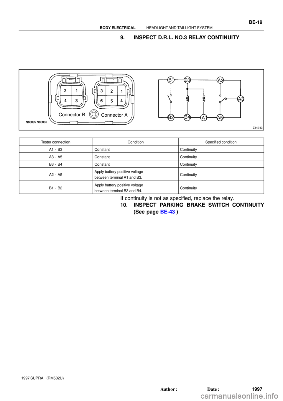
9. INSPECT D.R.L. NO.3 RELAY CONTINUITY
Tester connectionConditionSpecified condition
A1 - B3ConstantContinuity
A3 - A5ConstantContinuity
B3 - B4ConstantContinuity
A2 - A5Apply battery positive voltage
between terminal A1 and B3.Continuity
B1 - B2Apply battery positive voltage
between terminal B3 and B4.Continuity
If continuity is not as specified, replace the relay.
10. INSPECT PARKING BRAKE SWITCH CONTINUITY
(See page BE-43)
Page 195 of 1807
Z18230
Brake Fluid Level Warning Switch
Parking Brake Switch
Telltale Light LH
Telltale Light RHVehicle Speed Sensor
Light Failure Sensor
DOME Fuse
Combination Meter
Door Courtesy Switches GAUGE Fuse
ECU-B Fuse
IGN Fuse
PANEL Fuse
TAIL Fuse Integration
Fuel Sender Gauge
: Engine Coolant Temperature Sensor
: Engine Oil Level Sensor
: Low Oil Pressure Warning Switch
: Park/Neutral Position Switch
: Vehicle Speed Sensor 2JZ-GE2JZ-GTE
1
5
4
3
2 Relay� R/B No.2
J/B No.1
Meter Circuit �
�
�
�
�
�
1
1
5 4
3
2 1
2
3
4
5
BE0E7-01
- BODY ELECTRICALCOMBINATION METER
BE-39
2017 Author�: Date�:
1997 SUPRA (RM502U)
COMBINATION METER
LOCATION
Page 197 of 1807

I02078
Cruise Control Indicator :Fuel Gauge
:Engine Coolant Temperature Gauge
:Tachometer
:Speedometer
D.R.L. :Daytime Running Light
* :Engine Oil Level Delay Circuit
F
E
T
S
F
E
T
S C8
A10
A11
A9
A8
A13
C11
C10
B13
B12
B2
A1
C7
C5
A14
A7
A6
A3
C1
C2
C13
A5P
R
N
D
2
LB4
B10
B6
B7
B8
B11
B1
C9
A16
C4
C6
A15
A2
B3
C12 Fuel Level Warning
MANU Indicator
O/D OFF Indicator
Brake Warning
Bulb Check Relay
TRAC Indicator
Right Turn Indicator
High Beam Indicator
Master Warning
Illumination
SNOW IndicatorLeft Turn Indicator
No. Wire Harness Side
Brake Fluid Level Warning Switch
Parking Brake Switch
USA:TAIL (RH) Fuse, PANEL Fuse
Headlight Dimmer Switch
ECT ECU
Cruise Control ECU
TRAC ECU
Ground (Engine)
Engine Coolant Temperature Sender Gauge
Fuel Sender Gauge
Ground (Signal)
Turn Signal Switch
Starter Relay Generator L Terminal Igniter
Park/Neutral Position Switch (A/T Vehicle) A1
2
3
5
6
7
8
9
10
11
13
14
15
16
BGAUGE Fuse
O/D OFF Switch
USA:TAIL (RH) Fuse, PANEL Fuse
Park/Neutral Position Switch (P)
Park/Neutral Position Switch (N)
ECT ECU
Ground (Power)
Park/Neutral Position Switch (D)
Park/Neutral Position Switch (2)
Park/Neutral Position Switch (L) Park/Neutral Position Switch (R) 1
2
3
6
7
8
10
11
124
13
Engine Oil Level Sensor
Turn Signal Switch
Ground (Power)
Fuel Sender Gauge
GAUGE Fuse
Vehicle Speed Sensor (Terminal 2)
Vehicle Speed Sensor (Terminal 3)
USA:TAIL (RH) Fuse, PANEL Fuse
Light Control Rheostat Telltail Light RH (Terminal 11)
Telltail Light LH (Terminal 1)
Telltail Light LH (Terminal 6) 1
2
6
7
8
10
11
124
135
9 CCANADA:D.R.L. No.3 Relay
Clutch Start Switch (M/T Vehicle)
CANADA:D.R.L. No.3 Relay
CANADA:D.R.L. No.3 Relay
- BODY ELECTRICALCOMBINATION METER
BE-41
2019 Author�: Date�:
1997 SUPRA (RM502U)
Page 204 of 1807

17. INSPECT BR")
N08966
BE1217
Ignition
Switch
BatteryWarning Light
N09510
BE0044
Ignition
Switch
BatteryWarning Light BE-48
- BODY ELECTRICALCOMBINATION METER
2026 Author�: Date�:
1997 SUPRA (RM502U)
17. INSPECT BRAKE FLUID LEVEL WARNING SWITCH
CONTINUITY
(a) Remove the reservoir tank cap and strainer.
(b) Disconnect the connector.
(c) Check that there is no continuity between terminals with
the switch OFF (float up).
(d) Use syphon, etc. to take fluid out of the reservoir tank.
(e) Check that there is continuity between terminals with the
switch ON (float down).
(f) Pour the fluid back in the reservoir tank.
If operation is not as specified, replace the switch.
18. INSPECT BRAKE FLUID LEVEL WARNING LIGHT
(a) Disconnect the connector from the brake fluid warning
switch.
(b) Release the parking brake pedal.
(c) Connect terminals on the wire harness side of the level
warning switch connector.
(d) Start the engine, check that the warning light lights up.
If the warning light does not light up, test the bulb or wire har-
ness.
19. INSPECT PARKING BRAKE SWITCH CONTINUITY
(a) Check that there is continuity between terminal and
switch body with the switch ON (switch pin released).
(b) Check that there is no continuity between terminal and
switch body with the switch OFF (switch pin pushed in).
If operation is not as specified, replace the switch or inspect
ground point.
20. INSPECT PARKING BRAKE WARNING LIGHT
(a) Disconnect the connector from the parking brake switch
and the brake fluid warning switch.
(b) Ground terminal on the wire harness side connector.
(c) Start the engine, check that the warning light lights up.
If the warning light does not light up, test the bulb or inspect wire
harness.
Page 306 of 1807
BO0RA-01
H01986
Steering Column Cover
Combination Switch
No.2 Cover
No.3 Cover
Steering Wheel
Heater to Register No.2 DuctSteering Wheel Pad
Front Pillar Garnish RH
Assist Grip Finish Lower
LH Panel
Finish PanelFront Door Scuff
Inside Plate RH
Foot RestParking Brake Lever
Ash Receptacle Box
Console Upper Panel
Front Door Scuff
Inside Plate LH
Parking Brake
Hole CoverConsole Box
Console Box Mounting No.4 Bracket
GG
C
C
JI
I
I
II BO-50
- BODYINSTRUMENT PANEL
2130 Author�: Date�:
1997 SUPRA (RM502U)
INSTRUMENT PANEL
COMPONENTS
Page 310 of 1807
BO0RB-01
N08458
: 5 Clips
N087123 Clips
N117963 Clips
N08460
BO-54
- BODYINSTRUMENT PANEL
2134 Author�: Date�:
1997 SUPRA (RM502U)
REMOVAL
1. REMOVE STEERING WHEEL
(See page SR-1 1)
CAUTION:
�When storing the wheel pad, keep the upper surface
of the pad facing upward.
�Never disassemble the steering wheel pad.
2. REMOVE THESE PARTS:
HINT:
Tape a screwdriver tip before use.
(a) Front pillar garnishes
(b) Assist grip
(c) Foot rest
(d) Front door scuff inside plates
(e) Steering column cover
(f) Console upper panel
(g) Parking brake hole cover
(h) Console box
(i) Finish panel
(j) Finish lower LH panel
(k) Cluster finish panel
Page 312 of 1807

5. REMOVE FRONT PASSENGER AIRBAG ASSEMBLY
(a) Remove the 2 bolts from instrument panel.
Torque: 8.5")
H01987
N08465
N09351
N11635
BO-56
- BODYINSTRUMENT PANEL
2136 Author�: Date�:
1997 SUPRA (RM502U)
5. REMOVE FRONT PASSENGER AIRBAG ASSEMBLY
(a) Remove the 2 bolts from instrument panel.
Torque: 8.5 N´m (87 kgf´cm, 75 in.´lbf)
(b) Remove the 2 bolts from instrument panel reinforcement.
Torque: 20 N´m (204 kgf´cm, 15 ft´lbf)
(c) Remove the front passenger airbag assembly.
CAUTION:
�Do not store the front passenger airbag assembly
with the airbag door facing down.
�Never disassemble the front passenger airbag as-
sembly.
NOTICE:
At the time of installation, please refer to the following
items.
�Make sure the front passenger airbag assembly is
installed to the specified torque.
�Take care that the wirings do not interfere with other
parts and not pinched between other parts.
6. REMOVE THESE PARTS:
(a) Parking brake lever (2 bolts)
Torque: 59 N´m (600 kgf´cm, 43 ft´lbf)
(b) Side defroster No.2 nozzle
(c) Steering column (4 nuts)
Torque: 25 N´m (260 kgf´cm, 19 ft´lbf)
7. REMOVE INSTRUMENT PANEL
(a) Disconnect the connectors.
(b) Remove the nut, screw, 8 bolts and instrument panel.
Torque: 8.8 N´m (90 kgf´cm, 78 ft´lbf)
8. REMOVE INSTRUMENT PANEL REINFORCEMENT
(a) Remove the bolt, 2 nuts and instrument panel No.1 brace.
Torque: 21 N´m (210 kgf´cm, 15 ft´lbf)
(b) Remove the 6 bolts, 4 nuts and instrument panel rein-
forcement.
(c) Remove the bolt, 2 nuts and instrument panel side No.3
bracket.