Page 1664 of 1807
R07042SST
R07029
SST
R05852SST
- SUSPENSION AND AXLEREAR AXLE HUB
SA-45
1735 Author�: Date�:
1997 SUPRA (RM502U)
(c) Loosen the nut.
Torque: 150 N´m (1,525 kgf´cm, 110 ft´lbf)
(d) Using SST, disconnect the lower suspension arm No.2
from the axle carrier.
SST 09610-20012
NOTICE:
Be careful not to damage the ball joint bolt.
(e) Remove the nut.
12. REMOVE REAR AXLE CARRIER
(a) Remove the nut.
Torque: 108 N´m (1,100 kgf´cm, 80 ft´lbf)
(b) Using SST, disconnect the upper suspension arm from
the axle carrier.
SST 09628-6201 1
NOTICE:
Be careful not to damage the dust boot.
(c) Remove the rear axle carrier.
13. REMOVE REAR SUSPENSION ARM NO.1
(a) Remove the nut.
Torque: 59 N´m (600 kgf´cm, 43 ft´lbf)
(b) Using SST, disconnect the lower suspension arm No.1
from the axle carrier.
SST 09610-20012
NOTICE:
Be careful not to damage the dust boot.
HINT:
At the time of installation, before install the suspension arm
No.1, install the axle carrier to the vehicle.
Page 1667 of 1807
Z04024
SSTSA0PP-01
Z04025
- SUSPENSION AND AXLEREAR WHEEL HUB BOLT
SA-49
1739 Author�: Date�:
1997 SUPRA (RM502U)
REAR WHEEL HUB BOLT
REPLACEMENT
1. REMOVE REAR WHEEL
2. REMOVE BRAKE CALIPER AND DISC
(a) Remove the 2 bolts and brake caliper from the rear axle
hub.
(b) Support the brake caliper securely.
(c) Place matchmarks on the disc and axle hub.
(d) Remove the disc.
3. REMOVE HUB BOLT
Using SST, remove the hub bolt.
SST 09628-1001 1
4. INSTALL HUB BOLT
(a) Install washer and nut to a new hub bolt, as shown in the
illustration.
(b) Turn the wheel nut to pull the hub bolt through until the un-
derside of the hub bolt head touches the axle hub.
5. INSTALL DISC AND BRAKE CALIPER
(a) Install the disc.
(b) Install the 2 bolts and brake caliper to the rear axle hub.
Torque: 104 N´m (1,065 kgf´cm, 77 ft´lbf)
6. INSTALL REAR WHEEL
Torque: 103 N´m (1,050 kgf´cm, 76 ft´lbf)
Page 1669 of 1807
SA0PR-02
Z08967
TailpipeCenter Pipe
R07037
Matchmarks
R07024
R06937
- SUSPENSION AND AXLEREAR DRIVE SHAFT
SA-51
1741 Author�: Date�:
1997 SUPRA (RM502U)
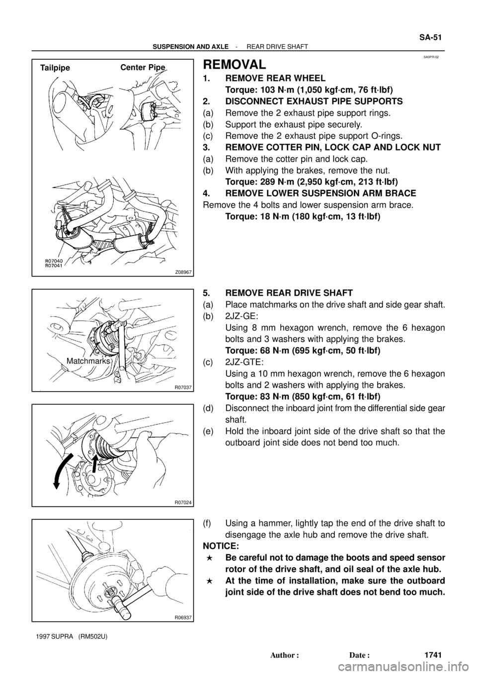
REMOVAL
1. REMOVE REAR WHEEL
Torque: 103 N´m (1,050 kgf´cm, 76 ft´lbf)
2. DISCONNECT EXHAUST PIPE SUPPORTS
(a) Remove the 2 exhaust pipe support rings.
(b) Support the exhaust pipe securely.
(c) Remove the 2 exhaust pipe support O-rings.
3. REMOVE COTTER PIN, LOCK CAP AND LOCK NUT
(a) Remove the cotter pin and lock cap.
(b) With applying the brakes, remove the nut.
Torque: 289 N´m (2,950 kgf´cm, 213 ft´lbf)
4. REMOVE LOWER SUSPENSION ARM BRACE
Remove the 4 bolts and lower suspension arm brace.
Torque: 18 N´m (180 kgf´cm, 13 ft´lbf)
5. REMOVE REAR DRIVE SHAFT
(a) Place matchmarks on the drive shaft and side gear shaft.
(b) 2JZ-GE:
Using 8 mm hexagon wrench, remove the 6 hexagon
bolts and 3 washers with applying the brakes.
Torque: 68 N´m (695 kgf´cm, 50 ft´lbf)
(c) 2JZ-GTE:
Using a 10 mm hexagon wrench, remove the 6 hexagon
bolts and 2 washers with applying the brakes.
Torque: 83 N´m (850 kgf´cm, 61 ft´lbf)
(d) Disconnect the inboard joint from the differential side gear
shaft.
(e) Hold the inboard joint side of the drive shaft so that the
outboard joint side does not bend too much.
(f) Using a hammer, lightly tap the end of the drive shaft to
disengage the axle hub and remove the drive shaft.
NOTICE:
�Be careful not to damage the boots and speed sensor
rotor of the drive shaft, and oil seal of the axle hub.
�At the time of installation, make sure the outboard
joint side of the drive shaft does not bend too much.
Page 1678 of 1807
Z04031
R08549
Less than 5 mm (0.20 in.)
- SUSPENSION AND AXLEREAR DIFFERENTIAL SIDE GEAR SHAFT OIL SEAL
SA-61
1751 Author�: Date�:
1997 SUPRA (RM502U)
7. INSTALL SIDE GEAR SHAFT
(a) Install a new snap ring to the side gear shaft.
(b) Coat MP grease onto the snap ring.
(c) Using a brass bar and hammer, install the side gear shaft
to the differential.
NOTICE:
Be careful not damage the side gear shaft and oil seal.
HINT:
Whether or not the side gear shaft is making contact with the
pinion shaft can be determined by the sound or feeling when
driving it in.
8. CHECK INSTALLATION OF SIDE GEAR SHAFT
Check that the side gear shaft will not come out by trying to pull
it out by hand.
9. INSTALL REAR DRIVE SHAFT (See page SA-58)
10. FILL DIFFERENTIAL WITH HYPOID GEAR OIL
Torque: 49 N´m (500 kgf´cm, 36 ft´lbf)
Oil grade: Hypoid gear oil API GL-5
Viscosity:
Above -18 °C (0 °F) SAE 90
Below -18 °C (0 °F) 80W-90 or SAE 80W
Capacity: 1.35 liters (1.43 US qts, 1.19 lmp. qts)
Page 1682 of 1807
SA0PY-02
R06615
Matchmarks
R06904
R06905
- SUSPENSION AND AXLEREAR DIFFERENTIAL CARRIER
SA-65
1755 Author�: Date�:
1997 SUPRA (RM502U)
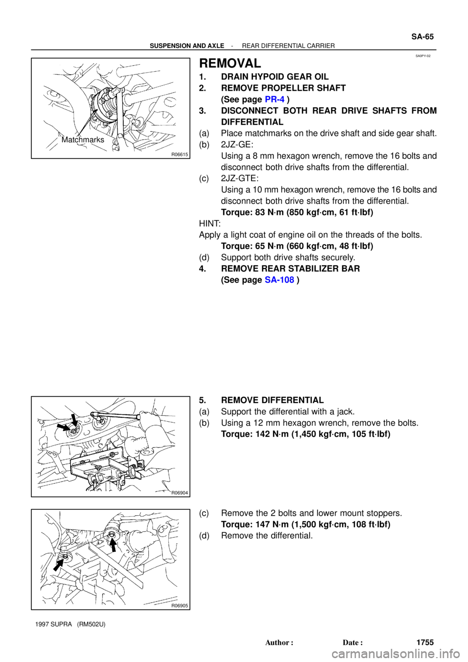
REMOVAL
1. DRAIN HYPOID GEAR OIL
2. REMOVE PROPELLER SHAFT
(See page PR-4)
3. DISCONNECT BOTH REAR DRIVE SHAFTS FROM
DIFFERENTIAL
(a) Place matchmarks on the drive shaft and side gear shaft.
(b) 2JZ-GE:
Using a 8 mm hexagon wrench, remove the 16 bolts and
disconnect both drive shafts from the differential.
(c) 2JZ-GTE:
Using a 10 mm hexagon wrench, remove the 16 bolts and
disconnect both drive shafts from the differential.
Torque: 83 N´m (850 kgf´cm, 61 ft´lbf)
HINT:
Apply a light coat of engine oil on the threads of the bolts.
Torque: 65 N´m (660 kgf´cm, 48 ft´lbf)
(d) Support both drive shafts securely.
4. REMOVE REAR STABILIZER BAR
(See page SA-108)
5. REMOVE DIFFERENTIAL
(a) Support the differential with a jack.
(b) Using a 12 mm hexagon wrench, remove the bolts.
Torque: 142 N´m (1,450 kgf´cm, 105 ft´lbf)
(c) Remove the 2 bolts and lower mount stoppers.
Torque: 147 N´m (1,500 kgf´cm, 108 ft´lbf)
(d) Remove the differential.
Page 1685 of 1807
R00027
Z08859
SST
(or 36 mm Deep
Socket)
R00025
SA-68
- SUSPENSION AND AXLEREAR DIFFERENTIAL CARRIER
1758 Author�: Date�:
1997 SUPRA (RM502U)
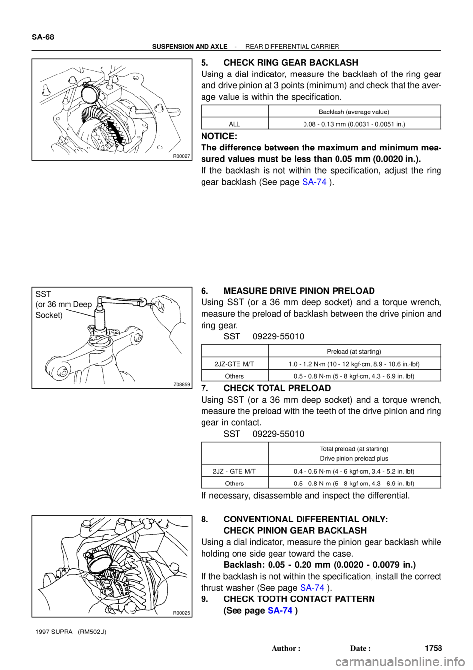
5. CHECK RING GEAR BACKLASH
Using a dial indicator, measure the backlash of the ring gear
and drive pinion at 3 points (minimum) and check that the aver-
age value is within the specification.
Backlash (average value)
ALL0.08 - 0.13 mm (0.0031 - 0.0051 in.)
NOTICE:
The difference between the maximum and minimum mea-
sured values must be less than 0.05 mm (0.0020 in.).
If the backlash is not within the specification, adjust the ring
gear backlash (See page SA-74).
6. MEASURE DRIVE PINION PRELOAD
Using SST (or a 36 mm deep socket) and a torque wrench,
measure the preload of backlash between the drive pinion and
ring gear.
SST 09229-55010
Preload (at starting)
2JZ-GTE M/T1.0 - 1.2 N´m (10 - 12 kgf´cm, 8.9 - 10.6 in.´lbf)
Others0.5 - 0.8 N´m (5 - 8 kgf´cm, 4.3 - 6.9 in.´lbf)
7. CHECK TOTAL PRELOAD
Using SST (or a 36 mm deep socket) and a torque wrench,
measure the preload with the teeth of the drive pinion and ring
gear in contact.
SST 09229-55010
Total preload (at starting)
Drive pinion preload plus
2JZ - GTE M/T0.4 - 0.6 N´m (4 - 6 kgf´cm, 3.4 - 5.2 in.´lbf)
Others0.5 - 0.8 N´m (5 - 8 kgf´cm, 4.3 - 6.9 in.´lbf)
If necessary, disassemble and inspect the differential.
8. CONVENTIONAL DIFFERENTIAL ONLY:
CHECK PINION GEAR BACKLASH
Using a dial indicator, measure the pinion gear backlash while
holding one side gear toward the case.
Backlash: 0.05 - 0.20 mm (0.0020 - 0.0079 in.)
If the backlash is not within the specification, install the correct
thrust washer (See page SA-74).
9. CHECK TOOTH CONTACT PATTERN
(See page SA-74)
Page 1692 of 1807
SA1143
Boiling Water
SA1158
Matchmarks
SA1148
SA1180
64 N´m (650 kgf´cm, 47 ft´lbf)
60 - 90°
R15897
SST
SST
- SUSPENSION AND AXLEREAR DIFFERENTIAL CARRIER
SA-75
1765 Author�: Date�:
1997 SUPRA (RM502U)
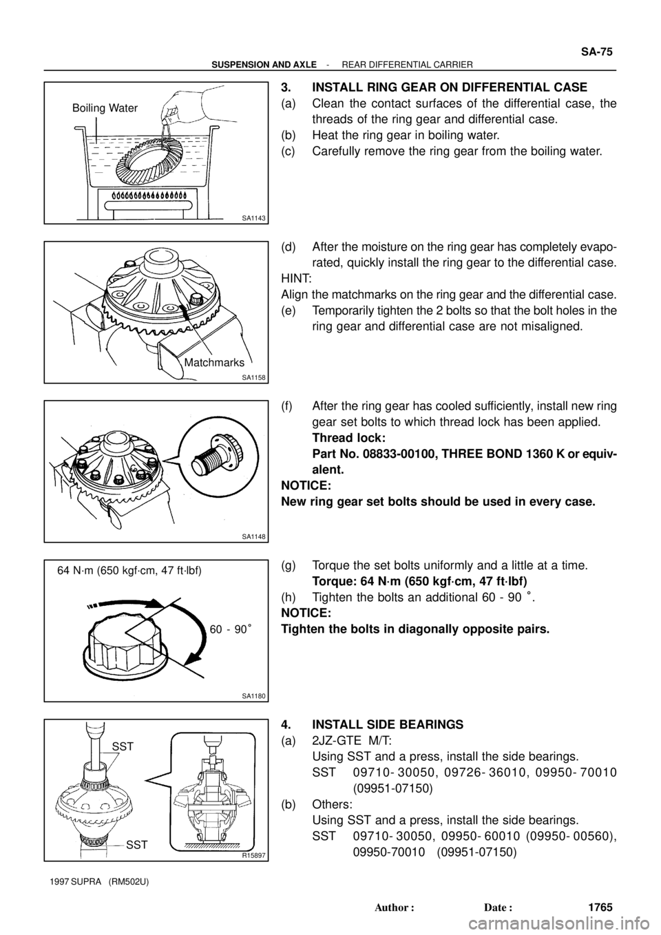
3. INSTALL RING GEAR ON DIFFERENTIAL CASE
(a) Clean the contact surfaces of the differential case, the
threads of the ring gear and differential case.
(b) Heat the ring gear in boiling water.
(c) Carefully remove the ring gear from the boiling water.
(d) After the moisture on the ring gear has completely evapo-
rated, quickly install the ring gear to the differential case.
HINT:
Align the matchmarks on the ring gear and the differential case.
(e) Temporarily tighten the 2 bolts so that the bolt holes in the
ring gear and differential case are not misaligned.
(f) After the ring gear has cooled sufficiently, install new ring
gear set bolts to which thread lock has been applied.
Thread lock:
Part No. 08833-00100, THREE BOND 1360 K or equiv-
alent.
NOTICE:
New ring gear set bolts should be used in every case.
(g) Torque the set bolts uniformly and a little at a time.
Torque: 64 N´m (650 kgf´cm, 47 ft´lbf)
(h) Tighten the bolts an additional 60 - 90 °.
NOTICE:
Tighten the bolts in diagonally opposite pairs.
4. INSTALL SIDE BEARINGS
(a) 2JZ-GTE M/T:
Using SST and a press, install the side bearings.
SST 09710- 30050, 09726- 36010, 09950- 70010
(09951-07150)
(b) Others:
Using SST and a press, install the side bearings.
SST 09710- 30050, 09950- 60010 (09950- 00560),
09950-70010 (09951-07150)
Page 1694 of 1807
R07252
SST
R07225
SST
SST
(or 36 mm Deep
Socket)
Z08859
SST
(or 36 mm Deep
Socket)
- SUSPENSION AND AXLEREAR DIFFERENTIAL CARRIER
SA-77
1767 Author�: Date�:
1997 SUPRA (RM502U)
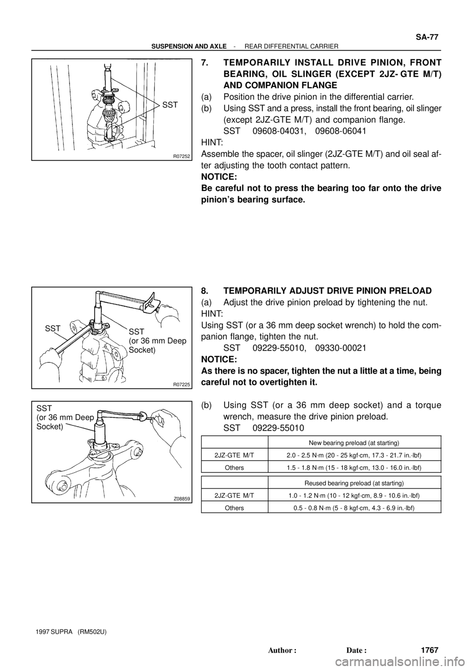
7. TEMPORARILY INSTALL DRIVE PINION, FRONT
BEARING, OIL SLINGER (EXCEPT 2JZ- GTE M/T)
AND COMPANION FLANGE
(a) Position the drive pinion in the differential carrier.
(b) Using SST and a press, install the front bearing, oil slinger
(except 2JZ-GTE M/T) and companion flange.
SST 09608-04031, 09608-06041
HINT:
Assemble the spacer, oil slinger (2JZ-GTE M/T) and oil seal af-
ter adjusting the tooth contact pattern.
NOTICE:
Be careful not to press the bearing too far onto the drive
pinion's bearing surface.
8. TEMPORARILY ADJUST DRIVE PINION PRELOAD
(a) Adjust the drive pinion preload by tightening the nut.
HINT:
Using SST (or a 36 mm deep socket wrench) to hold the com-
panion flange, tighten the nut.
SST 09229-55010, 09330-00021
NOTICE:
As there is no spacer, tighten the nut a little at a time, being
careful not to overtighten it.
(b) Using SST (or a 36 mm deep socket) and a torque
wrench, measure the drive pinion preload.
SST 09229-55010
New bearing preload (at starting)
2JZ-GTE M/T2.0 - 2.5 N´m (20 - 25 kgf´cm, 17.3 - 21.7 in.´lbf)
Others1.5 - 1.8 N´m (15 - 18 kgf´cm, 13.0 - 16.0 in.´lbf)
Reused bearing preload (at starting)
2JZ-GTE M/T1.0 - 1.2 N´m (10 - 12 kgf´cm, 8.9 - 10.6 in.´lbf)
Others0.5 - 0.8 N´m (5 - 8 kgf´cm, 4.3 - 6.9 in.´lbf)