Page 1695 of 1807
R15899
SST
R07227
SST
Upper SA-78
- SUSPENSION AND AXLEREAR DIFFERENTIAL CARRIER
1768 Author�: Date�:
1997 SUPRA (RM502U)
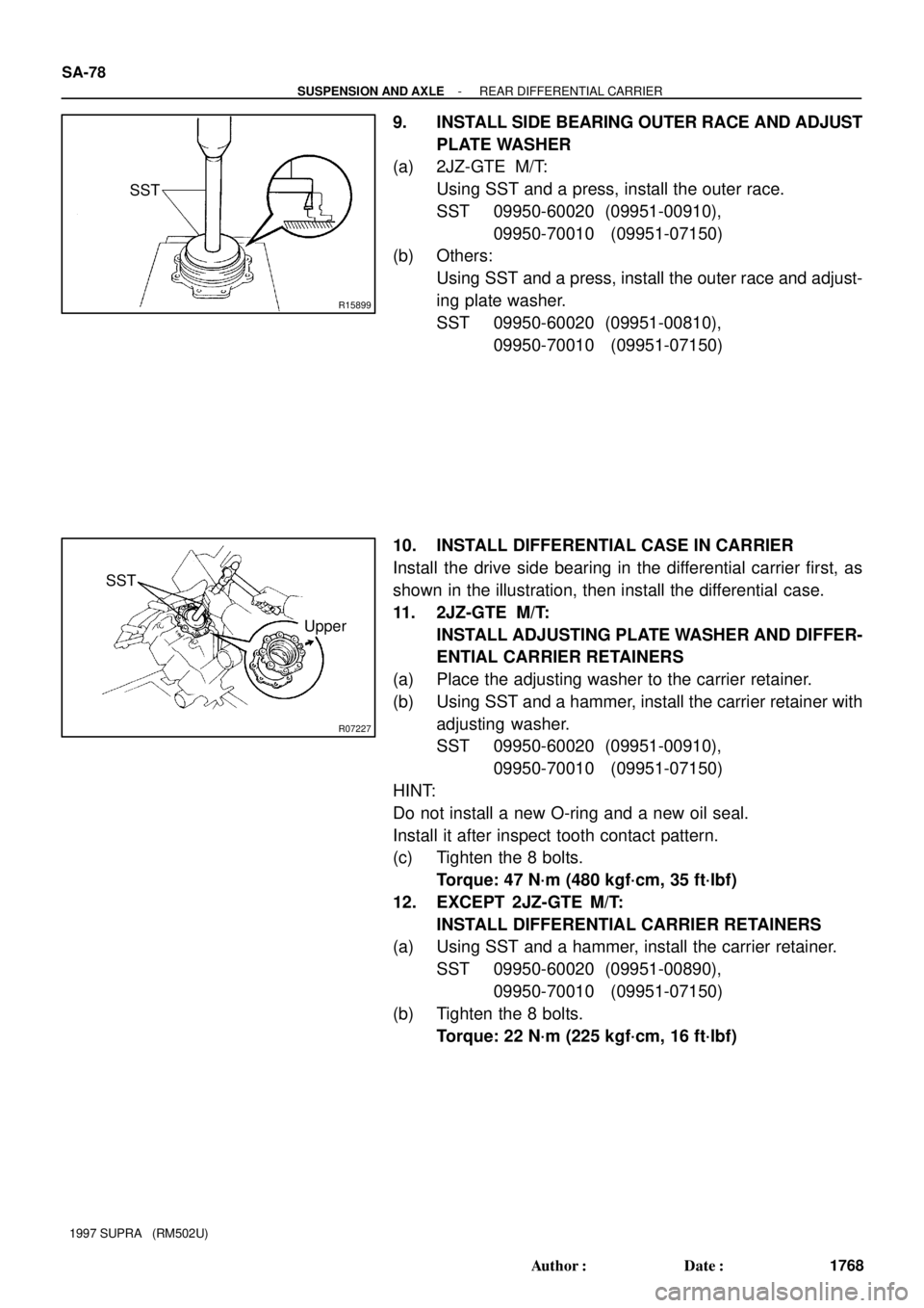
9. INSTALL SIDE BEARING OUTER RACE AND ADJUST
PLATE WASHER
(a) 2JZ-GTE M/T:
Using SST and a press, install the outer race.
SST 09950-60020 (09951-00910),
09950-70010 (09951-07150)
(b) Others:
Using SST and a press, install the outer race and adjust-
ing plate washer.
SST 09950-60020 (09951-00810),
09950-70010 (09951-07150)
10. INSTALL DIFFERENTIAL CASE IN CARRIER
Install the drive side bearing in the differential carrier first, as
shown in the illustration, then install the differential case.
11. 2JZ-GTE M/T:
INSTALL ADJUSTING PLATE WASHER AND DIFFER-
ENTIAL CARRIER RETAINERS
(a) Place the adjusting washer to the carrier retainer.
(b) Using SST and a hammer, install the carrier retainer with
adjusting washer.
SST 09950-60020 (09951-00910),
09950-70010 (09951-07150)
HINT:
Do not install a new O-ring and a new oil seal.
Install it after inspect tooth contact pattern.
(c) Tighten the 8 bolts.
Torque: 47 N´m (480 kgf´cm, 35 ft´lbf)
12. EXCEPT 2JZ-GTE M/T:
INSTALL DIFFERENTIAL CARRIER RETAINERS
(a) Using SST and a hammer, install the carrier retainer.
SST 09950-60020 (09951-00890),
09950-70010 (09951-07150)
(b) Tighten the 8 bolts.
Torque: 22 N´m (225 kgf´cm, 16 ft´lbf)
Page 1697 of 1807
Z08859
SST
(or 36 mm Deep
Socket)
R00020
SA-80
- SUSPENSION AND AXLEREAR DIFFERENTIAL CARRIER
1770 Author�: Date�:
1997 SUPRA (RM502U)
Except 2JZ-GTE M/T
No. Thickness mm(in.)No. Thickness mm (in.)No. Thickness mm (in.)
02 2.02 (0.0795)32 2.32 (0.0913)62 2.62 (0.1031)
04 2.04 (0.0803)34 2.34 (0.0921)64 2.64 (0.1039)
06 2.06 (0.0811)36 2.36 (0.0929)66 2.66 (0.1047)
08 2.08 (0.0819)38 2.38 (0.0937)68 2.68 (0.1055)
10 2.10 (0.0827)40 2.40 (0.0945)70 2.70 (0.1063)
12 2.12 (0.0835)42 2.42 (0.0953)72 2.72 (0.1071)
14 2.14 (0.0843)44 2.44 (0.0961)74 2.74 (0.1079)
16 2.16 (0.0850)46 2.46 (0.0969)76 2.76 (0.1087)
18 2.18 (0.0858)48 2.48 (0.0976)78 2.78 (0.1094)
20 2.20 (0.0866)50 2.50 (0.0984)80 2.80 (0.1102)
22 2.22 (0.0874)52 2.52 (0.0992)82 2.82 (0.1110)
24 2.24 (0.0882)54 2.54 (0.1000)84 2.84 (0.1118)
26 2.26 (0.0890)56 2.56 (0.1008)86 2.86 (0.1126)
28 2.28 (0.0898)58 2.58 (0.1016)-
30 2.30 (0.0906)60 2.60 (0.1024)-
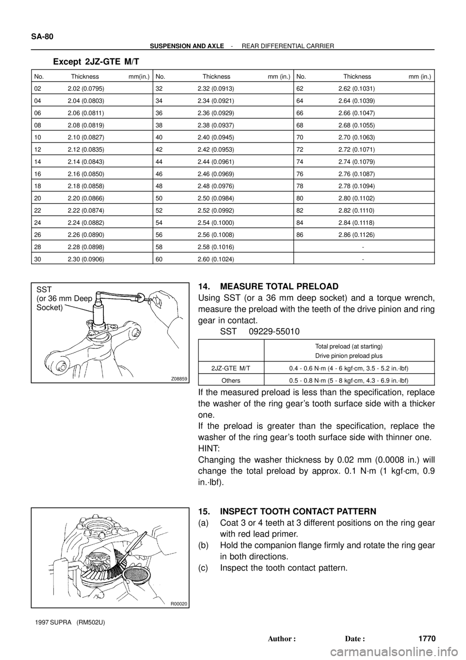
14. MEASURE TOTAL PRELOAD
Using SST (or a 36 mm deep socket) and a torque wrench,
measure the preload with the teeth of the drive pinion and ring
gear in contact.
SST 09229-55010
Total preload (at starting)
Drive pinion preload plus
2JZ-GTE M/T0.4 - 0.6 N´m (4 - 6 kgf´cm, 3.5 - 5.2 in.´lbf)
Others0.5 - 0.8 N´m (5 - 8 kgf´cm, 4.3 - 6.9 in.´lbf)
If the measured preload is less than the specification, replace
the washer of the ring gear's tooth surface side with a thicker
one.
If the preload is greater than the specification, replace the
washer of the ring gear's tooth surface side with thinner one.
HINT:
Changing the washer thickness by 0.02 mm (0.0008 in.) will
change the total preload by approx. 0.1 N´m (1 kgf´cm, 0.9
in.´lbf).
15. INSPECT TOOTH CONTACT PATTERN
(a) Coat 3 or 4 teeth at 3 different positions on the ring gear
with red lead primer.
(b) Hold the companion flange firmly and rotate the ring gear
in both directions.
(c) Inspect the tooth contact pattern.
Page 1701 of 1807
Z08859
SST
(or 36 mm Deep
Socket)
R07225
SST
(or 36 mm Deep
Socket) SST
R0721310 mm (0.39 in.)
R00032
SA-84
- SUSPENSION AND AXLEREAR DIFFERENTIAL CARRIER
1774 Author�: Date�:
1997 SUPRA (RM502U)
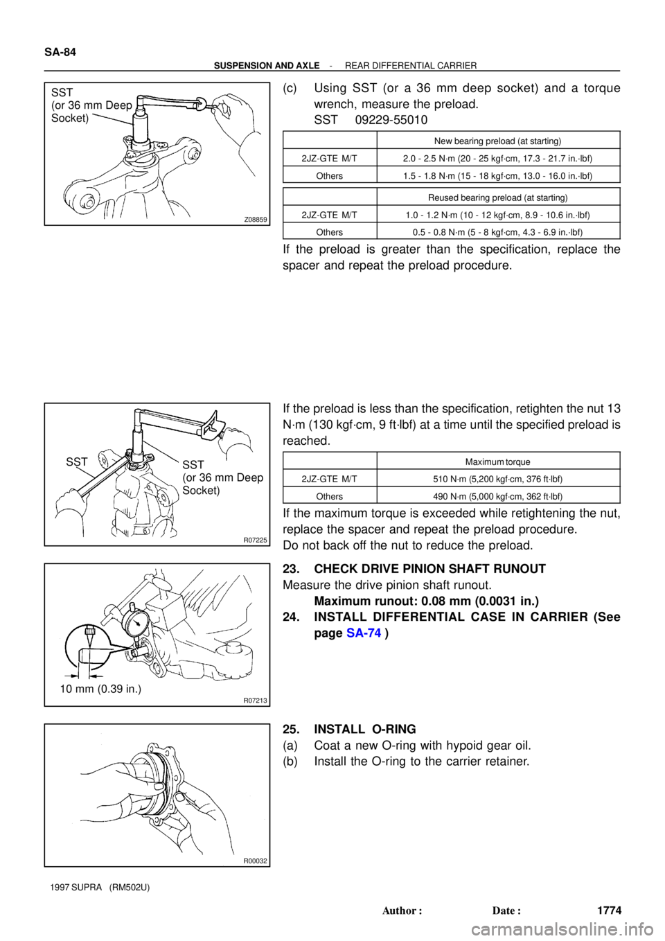
(c) Using SST (or a 36 mm deep socket) and a torque
wrench, measure the preload.
SST 09229-55010
New bearing preload (at starting)
2JZ-GTE M/T2.0 - 2.5 N´m (20 - 25 kgf´cm, 17.3 - 21.7 in.´lbf)
Others1.5 - 1.8 N´m (15 - 18 kgf´cm, 13.0 - 16.0 in.´lbf)
Reused bearing preload (at starting)
2JZ-GTE M/T1.0 - 1.2 N´m (10 - 12 kgf´cm, 8.9 - 10.6 in.´lbf)
Others0.5 - 0.8 N´m (5 - 8 kgf´cm, 4.3 - 6.9 in.´lbf)
If the preload is greater than the specification, replace the
spacer and repeat the preload procedure.
If the preload is less than the specification, retighten the nut 13
N´m (130 kgf´cm, 9 ft´lbf) at a time until the specified preload is
reached.
Maximum torque
2JZ-GTE M/T510 N´m (5,200 kgf´cm, 376 ft´lbf)
Others490 N´m (5,000 kgf´cm, 362 ft´lbf)
If the maximum torque is exceeded while retightening the nut,
replace the spacer and repeat the preload procedure.
Do not back off the nut to reduce the preload.
23. CHECK DRIVE PINION SHAFT RUNOUT
Measure the drive pinion shaft runout.
Maximum runout: 0.08 mm (0.0031 in.)
24. INSTALL DIFFERENTIAL CASE IN CARRIER (See
page SA-74)
25. INSTALL O-RING
(a) Coat a new O-ring with hypoid gear oil.
(b) Install the O-ring to the carrier retainer.
Page 1703 of 1807
Z16467
FIPG
R07455
SA-86
- SUSPENSION AND AXLEREAR DIFFERENTIAL CARRIER
1776 Author�: Date�:
1997 SUPRA (RM502U)
31. RECHECK BACKLASH, TOTAL PRELOAD AND
TOOTH CONTACT PATTERN (See page SA-74)
32. REMOVE DIFFERENTIAL CARRIER FROM OVER-
HAUL STAND, ETC.
33. INSTALL DIFFERENTIAL CARRIER COVER
(a) Clean the contact surfaces of the carrier and cover of any
residual FIPG material using cleaner.
(b) Coat FIPG to the carrier or cover.
FIPG:
Part No. 08826-00090, THREE BOND 1281 or equiva-
lent
NOTICE:
After installing the cover, wait at least 1 hour before filling
it with oil or running the vehicle.
(c) Install the carrier cover to the carrier with the 8 bolts.
Torque
2JZ-GTE M/T78 N´m (800 kgf´cm, 58 ft´lbf)
Others47 N´m (475 kgf´cm, 34 ft´lbf)
(d) Install the breather plug.
Torque: 21 N´m (210 kgf´cm, 15 ft´lbf)
Page 1706 of 1807
SA0Q5-01
R11102
SA-90
- SUSPENSION AND AXLEREAR SHOCK ABSORBER
1780 Author�: Date�:
1997 SUPRA (RM502U)
REMOVAL
1. w/ SPORT ROOF:
REMOVE THESE PARTS:
(See page BO-38)
�Rear seat cushion
�Rear seatback
�Tonneau cover retainer
�Holder garnish and holder
�Speaker grille
�Quarter trim board
2. REMOVE REAR WHEEL
Torque: 103 N´m (1,050 kgf´cm, 76 ft´lbf)
3. REMOVE REAR BRAKE CALIPER
(a) Remove the 2 bolts and brake caliper from the rear axle
carrier.
Torque: 104 N´m (1,065 kgf´cm, 77 ft´lbf)
(b) Support the brake caliper securely.
4. DISCONNECT REAR STABILIZER BAR LINK
Remove the nut and disconnect the stabilizer bar link from the
lower suspension arm No.2.
Torque: 74 N´m (750 kgf´cm, 54 ft´lbf)
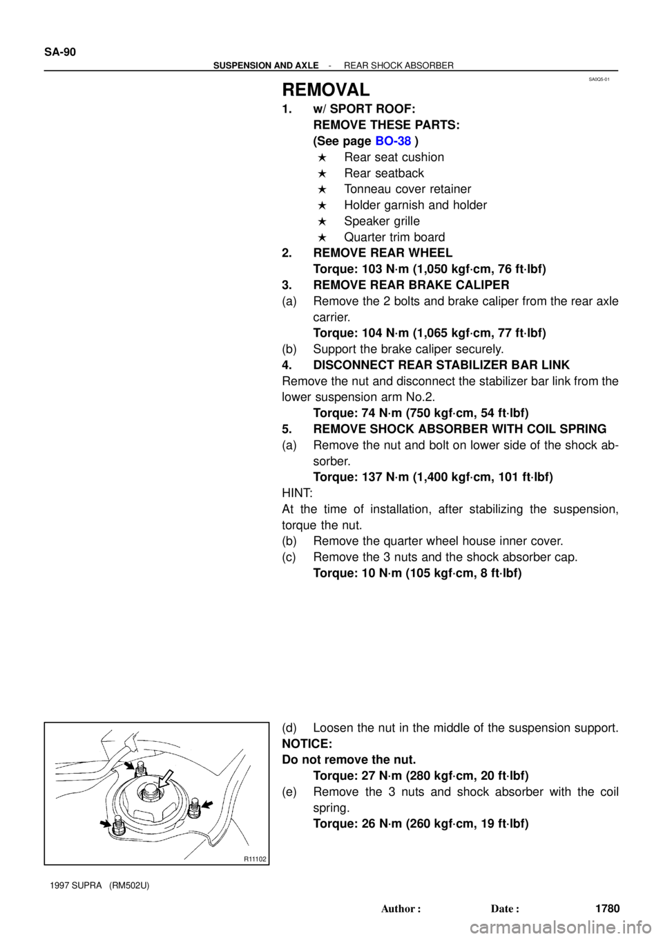
5. REMOVE SHOCK ABSORBER WITH COIL SPRING
(a) Remove the nut and bolt on lower side of the shock ab-
sorber.
Torque: 137 N´m (1,400 kgf´cm, 101 ft´lbf)
HINT:
At the time of installation, after stabilizing the suspension,
torque the nut.
(b) Remove the quarter wheel house inner cover.
(c) Remove the 3 nuts and the shock absorber cap.
Torque: 10 N´m (105 kgf´cm, 8 ft´lbf)
(d) Loosen the nut in the middle of the suspension support.
NOTICE:
Do not remove the nut.
Torque: 27 N´m (280 kgf´cm, 20 ft´lbf)
(e) Remove the 3 nuts and shock absorber with the coil
spring.
Torque: 26 N´m (260 kgf´cm, 19 ft´lbf)
Page 1713 of 1807
SA0QC-01
R07029
SST
R05881
- SUSPENSION AND AXLEREAR UPPER SUSPENSION ARM
SA-97
1787 Author�: Date�:
1997 SUPRA (RM502U)
REMOVAL
1. REMOVE REAR WHEEL
Torque: 103 N´m (1,050 kgf´cm, 76 ft´lbf)
2. REMOVE DRIVE SHAFT (See page SA-51)
3. REMOVE BRAKE CALIPER
(a) Remove the 2 bolts and brake caliper from the rear axle
carrier.
Torque: 104 N´m (1,065 kgf´cm, 77 ft´lbf)
(b) Support the brake caliper securely.
4. DISCONNECT ABS SPEED SENSOR AND WIRE HAR-
NESS
(a) Remove the bolt and disconnect the speed sensor from
the axle carrier.
Torque: 7.8 N´m (80 kgf´cm, 69 in.´lbf)
(b) Disconnect the speed sensor wire harness clamp from
the upper suspension arm.
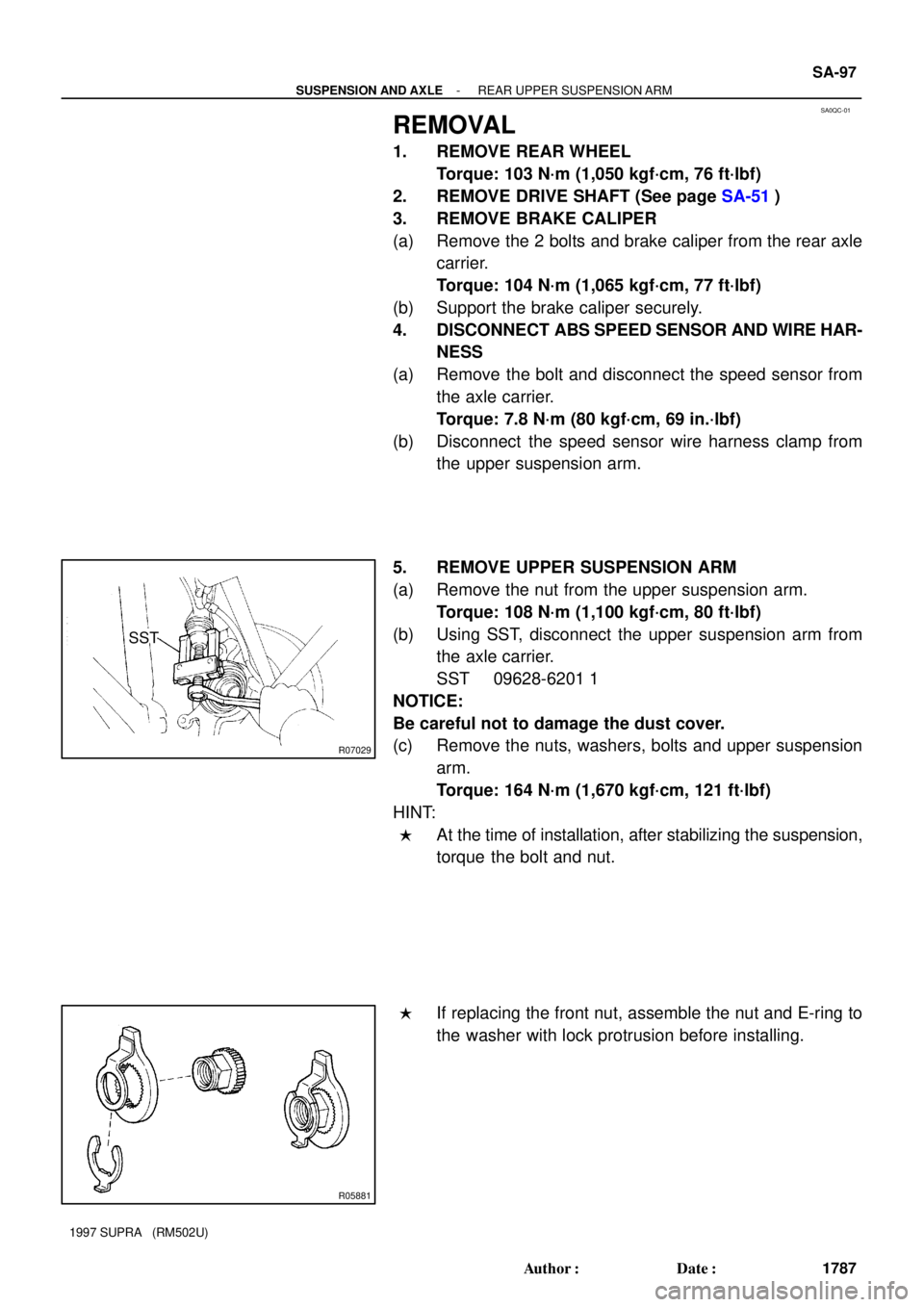
5. REMOVE UPPER SUSPENSION ARM
(a) Remove the nut from the upper suspension arm.
Torque: 108 N´m (1,100 kgf´cm, 80 ft´lbf)
(b) Using SST, disconnect the upper suspension arm from
the axle carrier.
SST 09628-6201 1
NOTICE:
Be careful not to damage the dust cover.
(c) Remove the nuts, washers, bolts and upper suspension
arm.
Torque: 164 N´m (1,670 kgf´cm, 121 ft´lbf)
HINT:
�At the time of installation, after stabilizing the suspension,
torque the bolt and nut.
�If replacing the front nut, assemble the nut and E-ring to
the washer with lock protrusion before installing.
Page 1714 of 1807
SA0QD-01
R05864
SA-98
- SUSPENSION AND AXLEREAR UPPER SUSPENSION ARM
1788 Author�: Date�:
1997 SUPRA (RM502U)
INSPECTION
INSPECT UPPER BALL JOINT FOR ROTATION CONDITION
(a) As shown in the illustration flip the ball joint stud back and
forth 5 times, before installing the nut.
(b) Using torque wrench, turn the nut continuously one turn
every 2 - 4 seconds and take the torque reading on the
5th turn.
Turning torque:
1.0 - 3.4 N´m (10 - 35 kgf´cm, 9 - 30 in.´lbf)
Page 1717 of 1807
SA0QH-01
R07312
R07045
SST
R07038
Matchmarks SA-102
- SUSPENSION AND AXLEREAR LOWER SUSPENSION ARM AND STRUT ROD
1792 Author�: Date�:
1997 SUPRA (RM502U)
REMOVAL
1. REMOVE REAR WHEEL
Torque: 103 N´m (1,050 kgf´cm, 76 ft´lbf)
2. REMOVE REAR DRIVE SHAFT (See page SA-51)
3. REMOVE BRAKE CALIPER
(a) Remove the 2 bolts and brake caliper from the rear axle
carrier.
Torque: 104 N´m (1,065 kgf´cm, 77 ft´lbf)
(b) Support the brake caliper securely.
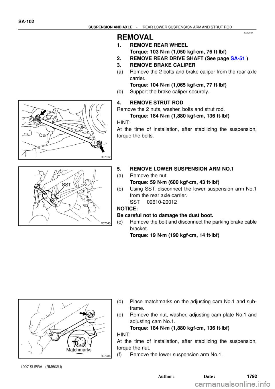
4. REMOVE STRUT ROD
Remove the 2 nuts, washer, bolts and strut rod.
Torque: 184 N´m (1,880 kgf´cm, 136 ft´lbf)
HINT:
At the time of installation, after stabilizing the suspension,
torque the bolts.
5. REMOVE LOWER SUSPENSION ARM NO.1
(a) Remove the nut.
Torque: 59 N´m (600 kgf´cm, 43 ft´lbf)
(b) Using SST, disconnect the lower suspension arm No.1
from the rear axle carrier.
SST 09610-20012
NOTICE:
Be careful not to damage the dust boot.
(c) Remove the bolt and disconnect the parking brake cable
bracket.
Torque: 19 N´m (190 kgf´cm, 14 ft´lbf)
(d) Place matchmarks on the adjusting cam No.1 and sub-
frame.
(e) Remove the nut, washer, adjusting cam plate No.1 and
adjusting cam No.1.
Torque: 184 N´m (1,880 kgf´cm, 136 ft´lbf)
HINT:
At the time of installation, after stabilizing the suspension,
torque the nut.
(f) Remove the lower suspension arm No.1.