Page 1641 of 1807
SA0OY-01
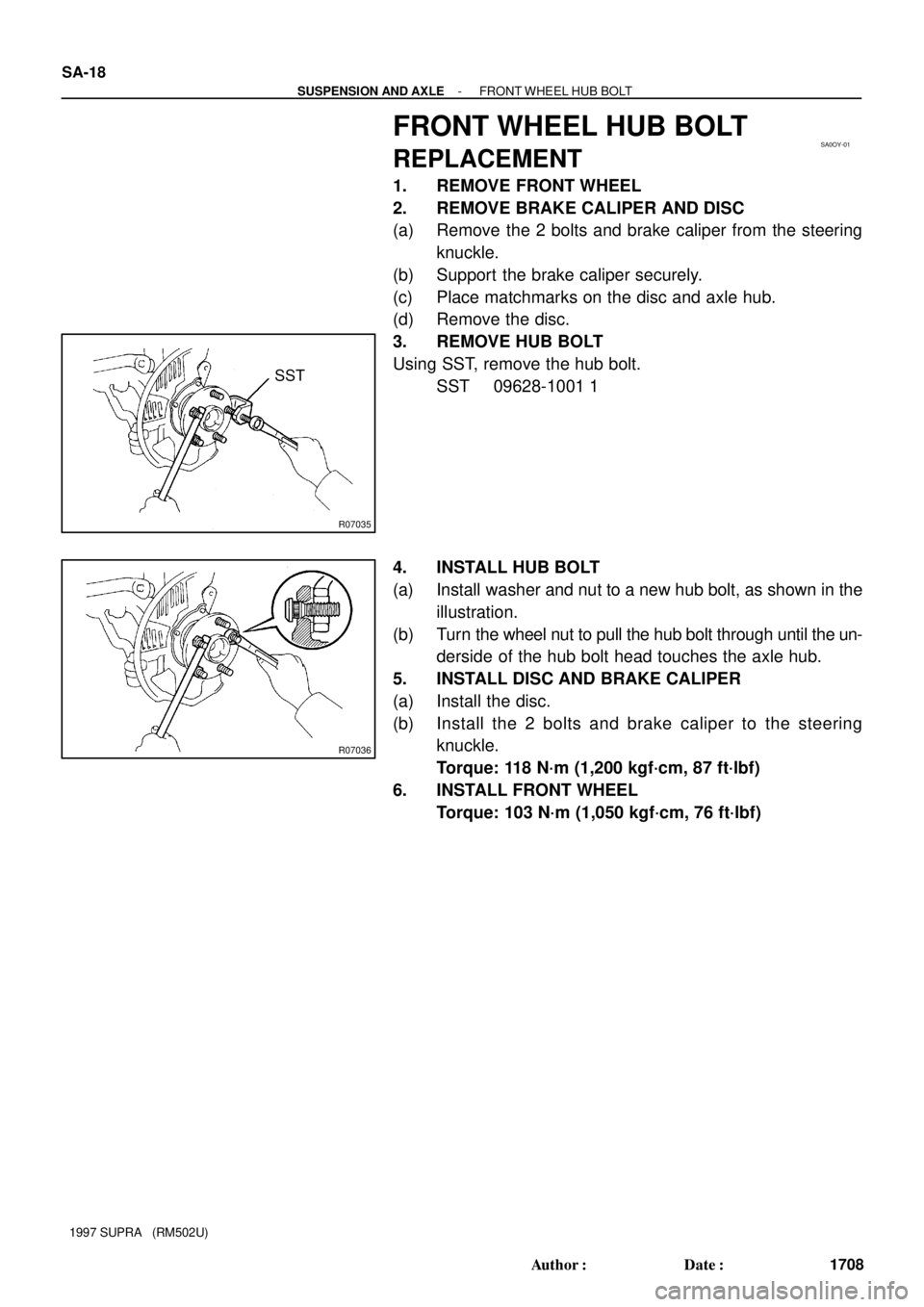
R07035
SST
R07036
SA-18
- SUSPENSION AND AXLEFRONT WHEEL HUB BOLT
1708 Author�: Date�:
1997 SUPRA (RM502U)
FRONT WHEEL HUB BOLT
REPLACEMENT
1. REMOVE FRONT WHEEL
2. REMOVE BRAKE CALIPER AND DISC
(a) Remove the 2 bolts and brake caliper from the steering
knuckle.
(b) Support the brake caliper securely.
(c) Place matchmarks on the disc and axle hub.
(d) Remove the disc.
3. REMOVE HUB BOLT
Using SST, remove the hub bolt.
SST 09628-1001 1
4. INSTALL HUB BOLT
(a) Install washer and nut to a new hub bolt, as shown in the
illustration.
(b) Turn the wheel nut to pull the hub bolt through until the un-
derside of the hub bolt head touches the axle hub.
5. INSTALL DISC AND BRAKE CALIPER
(a) Install the disc.
(b) Install the 2 bolts and brake caliper to the steering
knuckle.
Torque: 118 N´m (1,200 kgf´cm, 87 ft´lbf)
6. INSTALL FRONT WHEEL
Torque: 103 N´m (1,050 kgf´cm, 76 ft´lbf)
Page 1643 of 1807

REMOVAL
1. REMOVE FRONT WHEEL
Torque: 103 N´m (1,050 kgf´cm, 76 ft´lbf)
2. REMOVE B")
SA0P0-01
SA3578
R00159
SA-20
- SUSPENSION AND AXLEFRONT SHOCK ABSORBER
1710 Author�: Date�:
1997 SUPRA (RM502U)
REMOVAL
1. REMOVE FRONT WHEEL
Torque: 103 N´m (1,050 kgf´cm, 76 ft´lbf)
2. REMOVE BRAKE CALIPER
(a) Remove the 2 bolts and brake caliper from the steering
knuckle.
Torque: 118 N´m (1,200 kgf´cm, 87 ft´lbf)
(b) Support the brake caliper securely.
3. DISCONNECT ABS SPEED SENSOR AND WIRE HAR-
NESS
(a) Remove the bolt and disconnect the speed sensor from
the steering knuckle.
Torque: 7.8 N´m (80 kgf´cm, 69 in.´lbf)
(b) Remove the 3 bolts and disconnect the wire harness
clamp to prevent the wire harness from being damaged
when removing or installing the through bolt of the upper
suspension arm.
Torque: 5.4 N´m (55 kgf´cm, 48 in.´lbf)
4. REMOVE FRONT FENDER SPLASH SHIELD
5. LH side only:
MOVE WASHER TANK
(a) Remove the 2 washer tank set bolts.
(b) Move the washer tank away from the body.
6. DISCONNECT UPPER SUSPENSION ARM
(a) Remove the bolt and nut and disconnect the upper sus-
pension arm from the sub-frame.
Torque: 164 N´m (1,670 kgf´cm, 121 ft´lbf)
HINT:
At the time of installation, after stabilizing the suspension,
torque the nut.
(b) Support the upper suspension arm securely.
7. DISCONNECT STABILIZER BAR LINK
Remove the nut and disconnect the stabilizer bar link.
Torque: 74 N´m (750 kgf´cm, 54 ft´lbf)
HINT:
If the ball joint stud turns together with the nut, use a hexagon
wrench to hold the stud.
Page 1651 of 1807

REMOVAL
1. REMOVE FRONT WHEEL
Torque: 103 N´m (1,050 kgf´cm, 76 ft´lbf)
2")
SA0P8-01
SA3578
R07239
SST
- SUSPENSION AND AXLEFRONT UPPER SUSPENSION ARM
SA-29
1719 Author�: Date�:
1997 SUPRA (RM502U)
REMOVAL
1. REMOVE FRONT WHEEL
Torque: 103 N´m (1,050 kgf´cm, 76 ft´lbf)
2. REMOVE BRAKE CALIPER
(a) Remove the 2 bolts and brake caliper from the steering
knuckle.
Torque: 118 N´m (1,200 kgf´cm, 87 ft´lbf)
(b) Support the brake caliper securely.
3. DISCONNECT ABS SPEED SENSOR AND WIRE HAR-
NESS CLAMP
(a) Remove the bolt and disconnect the speed sensor from
the steering knuckle.
Torque: 7.8 N´m (80 kgf´cm, 69 in.´lbf)
(b) Remove the 3 bolts and disconnect the wire harness
clamp to prevent the wire harness being damaged when
removing or installing the through bolt.
Torque: 5.4 N´m (55 kgf´cm, 48 in.´lbf)
4. DISCONNECT UPPER SUSPENSION ARM
(a) Remove the cotter pin and the nut.
Torque: 103 N´m (1,050 kgf´cm, 76 ft´lbf)
(b) Using SST, disconnect the upper suspension arm from
the steering knuckle.
SST 09628-6201 1
5. REMOVE FRONT FENDER SPLASH SHIELD
6. LH side only:
MOVE WASHER TANK
(a) Remove the 2 washer tank set bolts.
(b) Move the washer tank away from the body.
7. REMOVE UPPER SUSPENSION ARM
(a) Remove the nut, 2 washers and bolt.
Torque: 164 N´m (1,670 kgf´cm, 121 ft´lbf)
HINT:
At the time of installation, after stabilizing the suspension,
torque the nut.
(b) Remove the upper suspension arm.
Page 1654 of 1807

REMOVAL
1. REMOVE FRONT WHEEL
Torque: 103 N´m (1,050 kgf´cm, 76 ft�")
SA0PD-01
R00159
R07240
SST
R06928
- SUSPENSION AND AXLEFRONT LOWER SUSPENSION ARM
SA-33
1723 Author�: Date�:
1997 SUPRA (RM502U)
REMOVAL
1. REMOVE FRONT WHEEL
Torque: 103 N´m (1,050 kgf´cm, 76 ft´lbf)
2. REMOVE ENGINE UNDER COVER
3. REMOVE BRAKE CALIPER
(a) Remove the 2 bolts and brake caliper from the steering
knuckle.
Torque: 118 N´m (1,200 kgf´cm, 87 ft´lbf)
(b) Support the brake caliper securely.
4. DISCONNECT STABILIZER BAR LINK FROM SHOCK
ABSORBER BRACKET
Remove the nut and disconnect the stabilizer bar link from the
shock absorber bracket.
Torque: 74 N´m (750 kgf´cm, 54 ft´lbf)
HINT:
If the ball joint stud turns together with the nut, use a hexagon
wrench to hold the stud.
5. DISCONNECT STEERING KNUCKLE
(a) Remove the clip and nut.
Torque: 125 N´m (1,270 kgf´cm, 92 ft´lbf)
(b) Using SST, disconnect the steering knuckle from the low-
er suspension arm.
SST 09628-6201 1
6. REMOVE LOWER SUSPENSION ARM
(a) Remove the nut, washer and bolt and disconnect the low-
er suspension arm from the shock absorber.
Torque: 143 N´m (1,460 kgf´cm, 106 ft´lbf)
HINT:
At the time of installation, after stabilizing the suspension,
torque the nut.
(b) Remove the nut, 2 bolts and the lower suspension arm
bracket stay.
Bolt: 44 N´m (450 kgf´cm, 32 ft´lbf)
Nut: 59 N´m (600 kgf´cm, 43 ft´lbf)
HINT:
At the time of installation, before installing the lower suspension
arm bracket stay, adjust the front wheel alignment.
Page 1658 of 1807
SA0PH-01
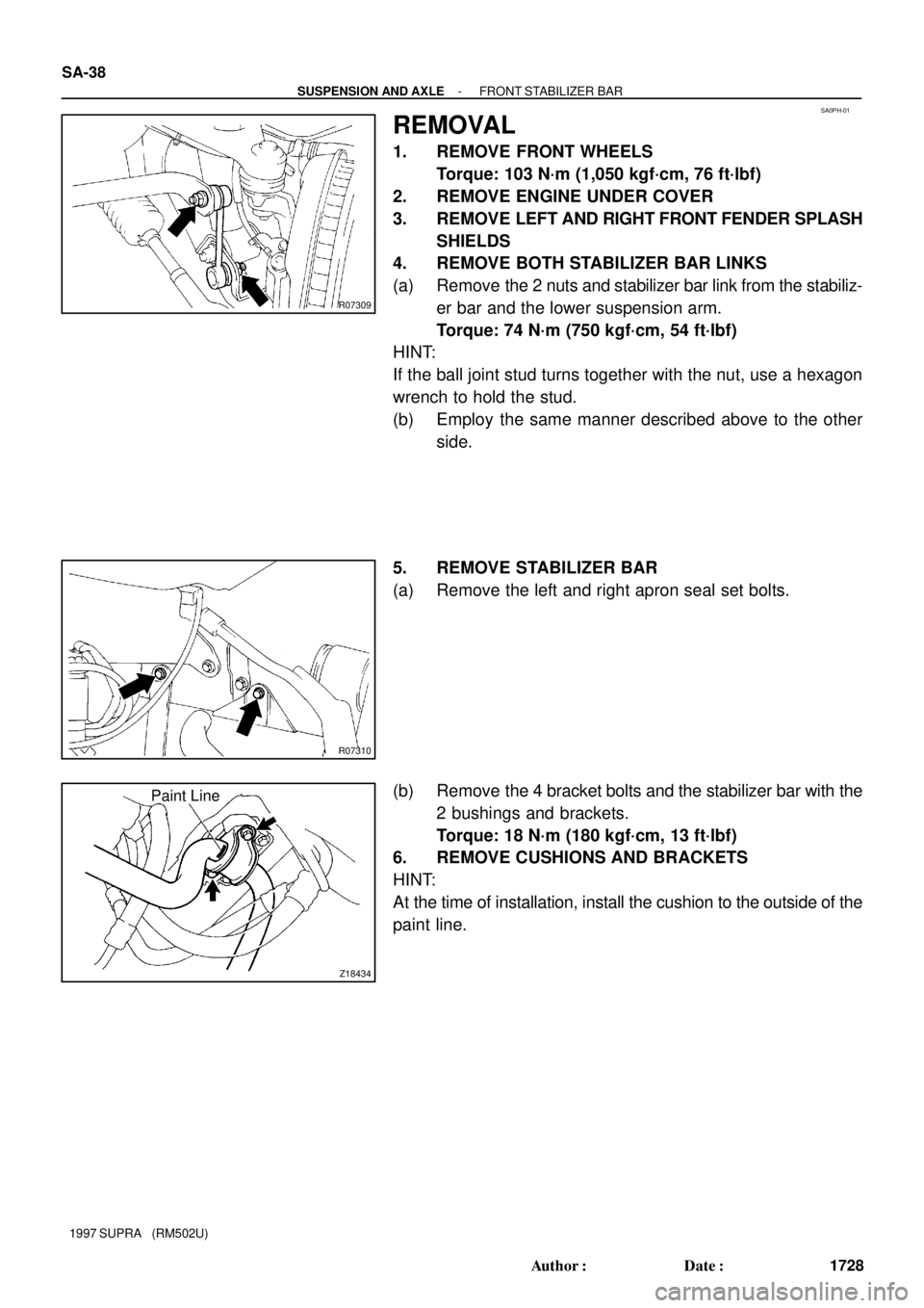
R07309
R07310
Z18434
Paint Line SA-38
- SUSPENSION AND AXLEFRONT STABILIZER BAR
1728 Author�: Date�:
1997 SUPRA (RM502U)
REMOVAL
1. REMOVE FRONT WHEELS
Torque: 103 N´m (1,050 kgf´cm, 76 ft´lbf)
2. REMOVE ENGINE UNDER COVER
3. REMOVE LEFT AND RIGHT FRONT FENDER SPLASH
SHIELDS
4. REMOVE BOTH STABILIZER BAR LINKS
(a) Remove the 2 nuts and stabilizer bar link from the stabiliz-
er bar and the lower suspension arm.
Torque: 74 N´m (750 kgf´cm, 54 ft´lbf)
HINT:
If the ball joint stud turns together with the nut, use a hexagon
wrench to hold the stud.
(b) Employ the same manner described above to the other
side.
5. REMOVE STABILIZER BAR
(a) Remove the left and right apron seal set bolts.
(b) Remove the 4 bracket bolts and the stabilizer bar with the
2 bushings and brackets.
Torque: 18 N´m (180 kgf´cm, 13 ft´lbf)
6. REMOVE CUSHIONS AND BRACKETS
HINT:
At the time of installation, install the cushion to the outside of the
paint line.
Page 1662 of 1807

REMOVAL
1. REMOVE REAR WHEEL
Torque: 103 N´m (1,050 kgf´cm, 76 ft´lbf)
2. REMOVE BRAKE")
SA0PL-02
Z18437
R 1111 0
- SUSPENSION AND AXLEREAR AXLE HUB
SA-43
1733 Author�: Date�:
1997 SUPRA (RM502U)
REMOVAL
1. REMOVE REAR WHEEL
Torque: 103 N´m (1,050 kgf´cm, 76 ft´lbf)
2. REMOVE BRAKE CALIPER AND DISC
(a) Remove the 2 bolts and brake caliper from the rear axle
hub.
Torque: 104 N´m (1,065 kgf´cm, 77 ft´lbf)
(b) Support the brake caliper securely.
(c) Place matchmarks on the disc and axle hub.
(d) Remove the disc.
3. CHECK BEARING BACKLASH AND AXLE HUB DEVI-
ATION
(a) Using a dial indicator near the center of the axle hub and
check the backlash in the bearing shaft direction.
Maximum: 0.05 mm (0.0020 in.)
If the backlash exceeds the maximum, replace the bearing.
(b) Using a dial indicator, check the deviation at the surface
of the axle hub outside the hub bolt.
Maximum: 0.05 mm (0.0020 in.)
If the deviation exceeds the maximum, replace the axle hub.
4. REMOVE DRIVE SHAFT LOCK NUT
(a) Install the disc and brake caliper.
Torque: 104 N´m (1,065 kgf´cm, 77 ft´lbf)
(b) Remove the cotter pin and lock cap.
(c) With applying the brakes, remove the nut.
Torque: 289 N´m (2,950 kgf´cm, 213 ft´lbf)
(d) Remove the brake caliper and disc.
5. REMOVE DRIVE SHAFT (See page SA-51)
6. REMOVE PARKING BRAKE SHOE
(See page BR-60)
7. DISCONNECT ABS SPEED SENSOR
Remove the bolt and disconnect the ABS speed sensor.
Torque: 7.8 N´m (80 kgf´cm, 69 in.´lbf)
8. DISCONNECT PARKING BRAKE CABLE
(a) Remove the 2 parking brake cable set bolts.
Torque: 8.0 N´m (80 kgf´cm, 69 in.´lbf)
(b) Remove the 2 backing plate set bolts.
Torque: 26 N´m (260 kgf´cm, 19 ft´lbf)
(c) Remove the bolt and shoe guide plate.
Torque: 18 N´m (185 kgf´cm, 13 ft´lbf)
Page 1667 of 1807
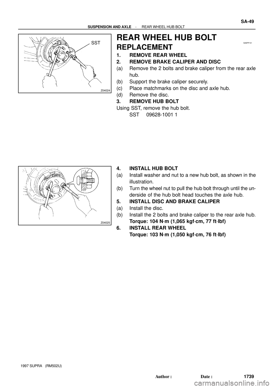
Z04024
SSTSA0PP-01
Z04025
- SUSPENSION AND AXLEREAR WHEEL HUB BOLT
SA-49
1739 Author�: Date�:
1997 SUPRA (RM502U)
REAR WHEEL HUB BOLT
REPLACEMENT
1. REMOVE REAR WHEEL
2. REMOVE BRAKE CALIPER AND DISC
(a) Remove the 2 bolts and brake caliper from the rear axle
hub.
(b) Support the brake caliper securely.
(c) Place matchmarks on the disc and axle hub.
(d) Remove the disc.
3. REMOVE HUB BOLT
Using SST, remove the hub bolt.
SST 09628-1001 1
4. INSTALL HUB BOLT
(a) Install washer and nut to a new hub bolt, as shown in the
illustration.
(b) Turn the wheel nut to pull the hub bolt through until the un-
derside of the hub bolt head touches the axle hub.
5. INSTALL DISC AND BRAKE CALIPER
(a) Install the disc.
(b) Install the 2 bolts and brake caliper to the rear axle hub.
Torque: 104 N´m (1,065 kgf´cm, 77 ft´lbf)
6. INSTALL REAR WHEEL
Torque: 103 N´m (1,050 kgf´cm, 76 ft´lbf)
Page 1669 of 1807

REMOVAL
1. REMOVE REAR WHEEL
Torque: 103 N´m")
SA0PR-02
Z08967
TailpipeCenter Pipe
R07037
Matchmarks
R07024
R06937
- SUSPENSION AND AXLEREAR DRIVE SHAFT
SA-51
1741 Author�: Date�:
1997 SUPRA (RM502U)
REMOVAL
1. REMOVE REAR WHEEL
Torque: 103 N´m (1,050 kgf´cm, 76 ft´lbf)
2. DISCONNECT EXHAUST PIPE SUPPORTS
(a) Remove the 2 exhaust pipe support rings.
(b) Support the exhaust pipe securely.
(c) Remove the 2 exhaust pipe support O-rings.
3. REMOVE COTTER PIN, LOCK CAP AND LOCK NUT
(a) Remove the cotter pin and lock cap.
(b) With applying the brakes, remove the nut.
Torque: 289 N´m (2,950 kgf´cm, 213 ft´lbf)
4. REMOVE LOWER SUSPENSION ARM BRACE
Remove the 4 bolts and lower suspension arm brace.
Torque: 18 N´m (180 kgf´cm, 13 ft´lbf)
5. REMOVE REAR DRIVE SHAFT
(a) Place matchmarks on the drive shaft and side gear shaft.
(b) 2JZ-GE:
Using 8 mm hexagon wrench, remove the 6 hexagon
bolts and 3 washers with applying the brakes.
Torque: 68 N´m (695 kgf´cm, 50 ft´lbf)
(c) 2JZ-GTE:
Using a 10 mm hexagon wrench, remove the 6 hexagon
bolts and 2 washers with applying the brakes.
Torque: 83 N´m (850 kgf´cm, 61 ft´lbf)
(d) Disconnect the inboard joint from the differential side gear
shaft.
(e) Hold the inboard joint side of the drive shaft so that the
outboard joint side does not bend too much.
(f) Using a hammer, lightly tap the end of the drive shaft to
disengage the axle hub and remove the drive shaft.
NOTICE:
�Be careful not to damage the boots and speed sensor
rotor of the drive shaft, and oil seal of the axle hub.
�At the time of installation, make sure the outboard
joint side of the drive shaft does not bend too much.