Page 1291 of 1807
CYLINDER HEAD
EM-39
1144 Author�: Date�:
1997 SUPRA (RM502U)
�If the seating is too low on the valve face,")
Z02456
45° 75°
Width
P02126
Z02457
Deviation
EM0801
EM0281
- ENGINE MECHANICAL (2JZ-GTE)CYLINDER HEAD
EM-39
1144 Author�: Date�:
1997 SUPRA (RM502U)
�If the seating is too low on the valve face, use 75°
and 45° cutters to correct the seat.
(d) Hand-lap the valve and valve seat with an abrasive com-
pound.
(e) After hand-lapping, clean the valve and valve seat.
12. INSPECT VALVE SPRINGS
(a) Using a steel square, measure the deviation of the valve
spring.
Maximum deviation: 2.0 mm (0.079 in.)
If deviation is greater than maximum, replace the valve spring.
(b) Using vernier calipers, measure the free length of the
valve spring.
Free length: 41.70 mm (1.6417 in.)
If the free length is not as specified, replace the valve spring.
(c) Using a spring tester, measure the tension of the valve
spring at the specified installed length.
Installed tension:
186 - 206 N (19.0 - 21.0 kgf, 42 - 46 lbf)
at 34.5 mm (1.358 in.)
If the installed tension is not as specified, replace the valve
spring.
Page 1371 of 1807

REPLACEMENT
CAUTION:
�Prolonged and repeated contact with mineral oil will
result in the")
LU0JZ-01
P12280
P12205
SST
Z04118
LU-4
- LUBRICATIONOIL AND FILTER
1451 Author�: Date�:
1997 SUPRA (RM502U)
REPLACEMENT
CAUTION:
�Prolonged and repeated contact with mineral oil will
result in the removal of natural fats from the skin,
leading to dryness, irritation and dermatitis. In addi-
tion, used engine oil contains potentially harmful
contaminants which may cause skin cancer.
�Exercise caution in order to minimize the length and
frequency of contact of your skin to used oil. Wear
protective clothing and gloves. Wash your skin thor-
oughly with soap and water, or use water-less hand
cleaner, to remove any used engine oil. Do not use
gasoline, thinners, or solvents.
�In order to preserve the environment, used oil and
used oil filters must be disposed of only at desig-
nated disposal sites.
1. DRAIN ENGINE OIL
(a) Remove the oil filler cap.
(b) Remove the oil drain plug, and drain the oil into a contain-
er.
2. REPLACE OIL FILTER
(a) Using SST, remove the oil filter.
SST 09228-07501
(b) Check and clean the oil filter installation surface.
(c) Apply clean engine oil to the gasket of a new oil filter.
Page 1423 of 1807

BRAKE
INSPECTION
1. INSPECT BRAKE LINE PIPES AND HOSES
HINT:
Check in a well lighted area. Check the entire circumferen")
B03050
MA01H-01
MA-6
- MAINTENANCEBRAKE
43 Author�: Date�:
1997 SUPRA (RM502U)
BRAKE
INSPECTION
1. INSPECT BRAKE LINE PIPES AND HOSES
HINT:
Check in a well lighted area. Check the entire circumference
and length of the brake hoses using a mirror as required. Turn
the front wheels fully right or left before checking the front brake.
(a) Check all brake lines and hoses for:
�Damage
�Wear
�Deformation
�Cracks
�Corrosion
�Leaks
�Bends
�Twists
(b) Check all clamps for tightness and connections for leak-
age.
(c) Check that the hoses and lines are clear of sharp edges,
moving parts and the exhaust system.
(d) Check that the lines installed in grommets pass through
the center of the grommets.
2. INSPECT FRONT AND REAR BRAKE PADS AND
DISCS
2JZ-GE:
Front: See page BR-23
Rear: See page BR-43
2JZ-GTE:
Front: See page BR-26
Rear: See page BR-46
HINT:
If a squealing or scraping noise comes from the brake during
driving, check the pad wear indicator to see if it is contacting the
disk rotor. If so, the disk pad should be replaced.
3. INSPECT PARKING BRAKE LININGS AND DRUMS
(See page BR-62)
Page 1463 of 1807

P12822
Plug
P12089
New
Gasket
FI1654
Fulcrum Length
30 cm
SST
P11303
New
O-Ring
New
Insulator
P12837
Delivery Pipe
O-Ring
Insulator
Intake
ManifoldInjector
Holder
Injector
SpacerInsulator
- SFI (2JZ-GTE)SFI SYSTEM
SF-3
1329 Author�: Date�:
1997 SUPRA (RM502U)
(3) Put a container under the connection.
(4) Slowly loosen the connection.
(5) Disconnect the connection.
(6) Plug the connection with a rubber plug.
(7) Reconnect the fuel pump connector.
(b) When connecting the flare nut or union bolt on the high
pressure pipe union, observe the following procedures:
(1) Union Bolt Type:
Always use a new gasket.
(2) Union Bolt Type:
Tighten the union bolt by hand.
(3) Union Bolt Type:
Tighten the union bolt to the specified torque.
Torque: 29 N´m (300 kgf´cm, 22 ft´lbf)
(4) Flare Nut Type:
Apply a light coat of engine oil to the flare nut and
tighten the flare nut by hand.
(5) Flare Nut Type:
Using SST, tighten the flare nut to the specified
torque.
SST 09631-22020
Torque: 30 N´m (310 kgf´cm, 22 ft´lbf)
HINT:
Use a torque wrench with a fulcrum length of 30 cm (11.81 in.).
(c) Observe the following precautions when removing and
installing the injectors.
(1) Never reuse the O-ring.
(2) When placing a new O-ring on the injector, take
care not to damage it in any way.
(3) Coat a new O-ring with spindle oil or gasoline be-
fore installing-never use engine, gear or brake oil.
(d) Install the injector to the delivery pipe and intake manifold
as shown in the illustration.
Page 1490 of 1807
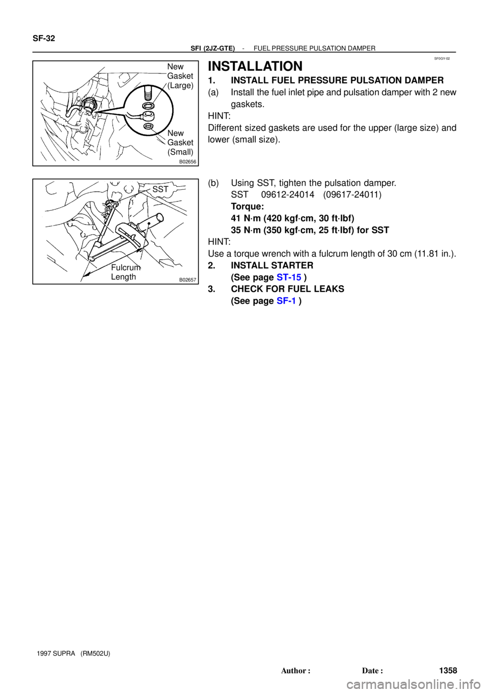
SF0GY-02
B02656
New
Gasket
(Large)
New
Gasket
(Small)
B02657
Fulcrum
LengthSST SF-32
- SFI (2JZ-GTE)FUEL PRESSURE PULSATION DAMPER
1358 Author�: Date�:
1997 SUPRA (RM502U)
INSTALLATION
1. INSTALL FUEL PRESSURE PULSATION DAMPER
(a) Install the fuel inlet pipe and pulsation damper with 2 new
gaskets.
HINT:
Different sized gaskets are used for the upper (large size) and
lower (small size).
(b) Using SST, tighten the pulsation damper.
SST 09612-24014 (09617-24011)
Torque:
41 N´m (420 kgf´cm, 30 ft´lbf)
35 N´m (350 kgf´cm, 25 ft´lbf) for SST
HINT:
Use a torque wrench with a fulcrum length of 30 cm (11.81 in.).
2. INSTALL STARTER
(See page ST-15)
3. CHECK FOR FUEL LEAKS
(See page SF-1)
Page 1492 of 1807
SF0H1-01
BO0919
Crack
Leakage
FI1654
SSTUse SST
(310 kgf´cm, 22 ft´lbf)
Fulcrum Length
(11.81 in.)
SST : 09631 - 22020
30 N´m
30 cm
FU0041
Pipe2 - 7mm(0.08-0.28 in.)
Hose
Clip
0 -3mm(0 - 0.12 in.)
- SFI (2JZ-GTE)FUEL TANK AND LINE
SF-35
1361 Author�: Date�:
1997 SUPRA (RM502U)
INSPECTION
INSPECT FUEL TANK AND LINE
(a) Check the fuel lines for cracks or leakage, and all connec-
tions for deformation.
(b) Check the fuel tank vapor vent system hoses and connec-
tions for looseness, sharp bends or damage.
(c) Check the fuel tank for deformation, cracks, fuel leakage
or tank band looseness.
(d) Check the filler neck for damage or fuel leakage.
(e) Hose and tube connections are as shown in the illustra-
tion.
If a problem is found, repair or replace the part as necessary.
Page 1552 of 1807

Terminal
Rectifier
Terminal
P10625
Ohmmeter
Negative (-)
Terminal CH-12
- CHARGINGGENERATOR
1535 Author�: Date�:
1997 SUPRA (RM502U)
6. INSPECT EXPOSED BRU")
P13535
Length
P10624
Ohmmeter
Positive (+)
Terminal
Rectifier
Terminal
P10625
Ohmmeter
Negative (-)
Terminal CH-12
- CHARGINGGENERATOR
1535 Author�: Date�:
1997 SUPRA (RM502U)
6. INSPECT EXPOSED BRUSH LENGTH
Using a vernier caliper, measure the exposed length.
Standard exposed length:
9.5 - 11.5 mm (0.347 - 0.453 in.)
Minimum exposed length:
1.5 mm (0.059 in.)
If the exposed length is less than minimum, replace the brush
holder.
7. INSPECT POSITIVE RECTIFIER
(a) Using an ohmmeter, connect one tester probe to the posi-
tive (+) terminal and the other to each rectifier terminal.
(b) Reverse the polarity of the tester probes and repeat step
(a).
(c) Check that one shows continuity and the other shows no
continuity.
If continuity is not as specified, replace the rectifier holder.
8. INSPECT NEGATIVE RECTIFIER
(a) Using an ohmmeter, connect one tester probe to each
negative (-) terminal and the other to each rectifier termi-
nal.
(b) Reverse the polarity of the tester probes and repeat step
(a).
(c) Check that one shows continuity and the other shows no
continuity.
If continuity is not as specified, replace the rectifier holder.
9. INSPECT FRONT BEARING
Check that the bearing is not rough or worn.
10. INSPECT REAR BEARING
Check that the bearing is not rough or worn.
Page 1564 of 1807

3. INSPECT FIE")
P10588
Ohmmeter
Continuity
P10589
Ohmmeter
No Continuity
Z07019
Brush Holder Side
Field Frame Side
Length
Length
ST0019
ST-8
- STARTINGSTARTER
1515 Author�: Date�:
1997 SUPRA (RM502U)
3. INSPECT FIELD COIL
(a) Check the field coil for open circuit.
Using an ohmmeter, check that there is continuity be-
tween the lead wire and field coil brush lead.
If there is no continuity, replace the field frame.
(b) Check the field coil for ground.
Using an ohmmeter, check that there is no continuity be-
tween the field coil end and field frame.
If there is continuity, replace the field frame.
4. INSPECT BRUSHES
Using a vernier caliper, measure the brush length.
Standard length: 15.5 mm (0.610 in.)
Minimum length: 10.0 mm (0.394 in.)
If the length is less than minimum, replace the brush holder and
field frame.
5. INSPECT BRUSH SPRINGS
Check the brush spring load. Take the pull scale reading the
instant the brush spring separates from the brush.
Standard spring installed load:
17.6 - 23.5 N (1.8 - 2.4 kgf, 3.9 - 5.3 lbf)
Minimum spring installed load:
11.8 N (1.2 kgf, 2.6 lbf)
If the installed load is less than minimum, replace the brush
springs.

Fulcrum Length
(11.81 in.)
SST : 09631 - 22020
30 N´m
30 cm
FU0041
Pipe2 - 7mm(0.08-0.28 in.)
Hose
Clip
0 -3mm(0 - 0.12 in.)")