Page 2933 of 3342
B4M0430
8T1
CHECK GENERATOR.
1) Start engine.
2) Idling after warm-up.
3) Measure voltage between generator B terminal and
chassis ground.
Terminal
Generator B terminal—Chassis ground:
: Is the voltage between 10 V and 17 V?
: Go to step8T2.
: Repair generator.
8T2
CHECK BATTERY TERMINAL.
Turn ignition switch to OFF.
: Are the positive and negative battery termi-
nals tightly clamped?
: Go to step8T3.
: Tighten the clamp of terminal.
B4M1234A
8T3CHECK INPUT VOLTAGE OF
ABSCM&H/U.
1) Disconnect connector from ABSCM&H/U.
2) Run the engine at idle.
3) Measure voltage between ABSCM&H/U connector and
chassis ground.
Connector & terminal
(F49) No. 1 (+)—Chassis ground (�):
: Is the voltage between 10 V and 17 V?
: Go to step8T4.
: Repair harness connector between battery, igni-
tion switch and ABSCM&H/U.
57
4-4dBRAKES [ABS 5.3i TYPE]
8. Diagnostics Chart with Trouble Code by ABS Warning Light
Page 2934 of 3342
B4M1243A
8T4CHECK GROUND CIRCUIT OF
ABSCM&H/U.
1) Turn ignition switch to OFF.
2) Measure resistance between ABSCM&H/U connector
and chassis ground.
Connector & terminal
(F49) No. 23—Chassis ground:
: Is the resistance less than 0.5Ω?
: Go to step8T5.
: Repair ABSCM&H/U ground harness.
8T5CHECK POOR CONTACT IN CONNEC-
TORS.
: Is there poor contact in connectors between
generator, battery and ABSCM&H/U?
to FOREWORD [T3C1].>
: Repair connector.
: Go to step8T6.
8T6
CHECK ABSCM&H/U.
1) Connect all connectors.
2) Erase the memory.
3) Perform inspection mode.
4) Read out the trouble code.
: Is the same trouble code as in the current
diagnosis still being output?
: Replace ABSCM&H/U.
: Go to step8T7.
8T7CHECK ANY OTHER TROUBLE CODES
APPEARANCE.
: Are other trouble codes being output?
: Proceed with the diagnosis corresponding to the
trouble code.
: A temporary poor contact.
58
4-4dBRAKES [ABS 5.3i TYPE]
8. Diagnostics Chart with Trouble Code by ABS Warning Light
Page 2935 of 3342
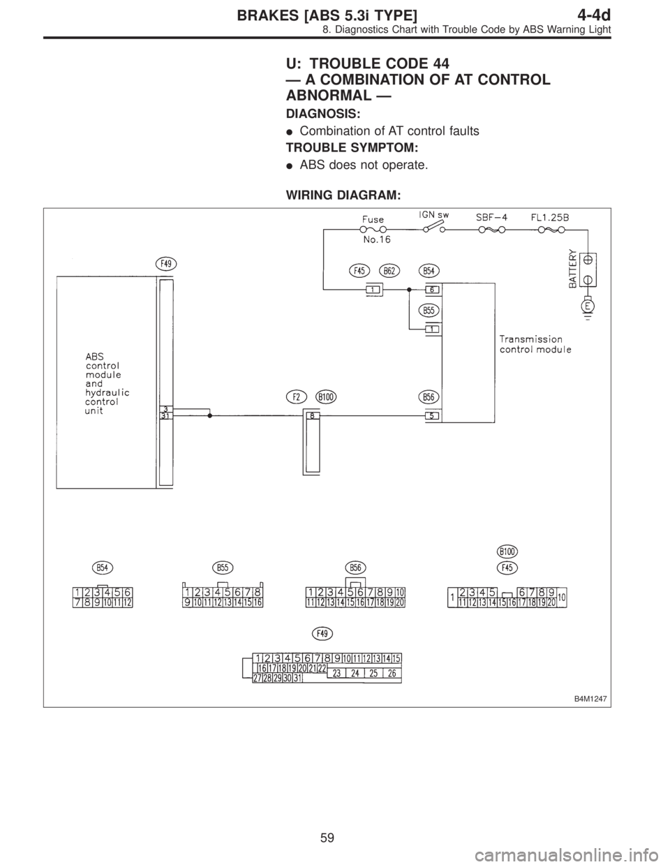
U: TROUBLE CODE 44
—A COMBINATION OF AT CONTROL
ABNORMAL—
DIAGNOSIS:
�Combination of AT control faults
TROUBLE SYMPTOM:
�ABS does not operate.
WIRING DIAGRAM:
B4M1247
59
4-4dBRAKES [ABS 5.3i TYPE]
8. Diagnostics Chart with Trouble Code by ABS Warning Light
Page 2936 of 3342
B4M1248A
8U1CHECK SPECIFICATIONS OF THE
ABSCM.
Check specifications of the mark to the ABSCM&H/U.
Mark Model
C3 AWD AT
C4 AWD MT
: Is an ABSCM&H/U for AT model installed on
a MT model?
: Replace ABSCM&H/U.
: Go to step8U2.
B4M1249A
8U2
CHECK GROUND SHORT OF HARNESS.
1) Turn ignition switch to OFF.
2) Disconnect two connectors from TCM.
3) Disconnect connector from ABSCM&H/U.
4) Measure resistance between ABSCM&H/U connector
and chassis ground.
Connector & terminal
(F49) No. 3—Chassis ground:
: Is the resistance more than 1 MΩ?
: Go to step8U3.
: Repair harness between TCM and ABSCM&H/U.
B4M1250A
8U3
CHECK BATTERY SHORT OF HARNESS.
Measure voltage between ABSCM&H/U connector and
chassis ground.
Connector & terminal
(F49) No. 3 (+)—Chassis ground (�):
: Is the voltage less than 1 V?
: Go to step8U4.
: Repair harness between TCM and ABSCM&H/U.
60
4-4dBRAKES [ABS 5.3i TYPE]
8. Diagnostics Chart with Trouble Code by ABS Warning Light
Page 2937 of 3342
B4M1250A
8U4
CHECK BATTERY SHORT OF HARNESS.
1) Turn ignition switch to ON.
2) Measure voltage between ABSCM&H/U connector and
chassis ground.
Connector & terminal
(F49) No. 3 (+)—Chassis ground (�):
: Is the voltage less than 1 V?
: Go to step8U5.
: Repair harness between TCM and ABSCM&H/U.
B4M1251A
8U5
CHECK TCM.
1) Turn ignition switch to OFF.
2) Connect all connectors to TCM.
3) Turn ignition switch to ON.
4) Measure voltage between TCM connector terminal and
chassis ground.
Connector & terminal
(B56) No. 5 (+)—Chassis ground (�):
: Is the voltage between 10 V and 15 V?
: Go to step8U7.
: Go to step8U6.
8U6
CHECK AT.
: Is the AT functioning normally?
: Replace TCM.
: Repair AT.
61
4-4dBRAKES [ABS 5.3i TYPE]
8. Diagnostics Chart with Trouble Code by ABS Warning Light
Page 2938 of 3342
 No. 3 (+)—Chassis ground (�):
(F49) No. 31 (+)—Chassis ground")
B4M1252A
8U7
CHECK OPEN CIRCUIT OF HARNESS.
Measure voltage between ABSCM&H/U connector and
chassis ground.
Connector & terminal
(F49) No. 3 (+)—Chassis ground (�):
(F49) No. 31 (+)—Chassis ground (�):
: Is the voltage between 10 V and 15 V?
: Go to step8U8.
: Repair harness/connector between TCM and
ABSCM&H/U.
8U8CHECK POOR CONTACT IN CONNEC-
TORS.
: Is there poor contact in connectors between
TCM and ABSCM&H/U?
WORD [T3C1].>
: Repair connector.
: Go to step8U9.
8U9
CHECK ABSCM&H/U.
1) Turn ignition switch to OFF.
2) Connect all connectors.
3) Erase the memory.
4) Perform inspection mode.
5) Read out the trouble code.
: Is the same trouble code as in the current
diagnosis still being output?
: Replace ABSCM&H/U.
: Go to step8U10.
8U10CHECK ANY OTHER TROUBLE CODES
APPEARANCE.
: Are other trouble codes being output?
: Proceed with the diagnosis corresponding to the
trouble code.
: A temporary poor contact.
62
4-4dBRAKES [ABS 5.3i TYPE]
8. Diagnostics Chart with Trouble Code by ABS Warning Light
Page 2939 of 3342
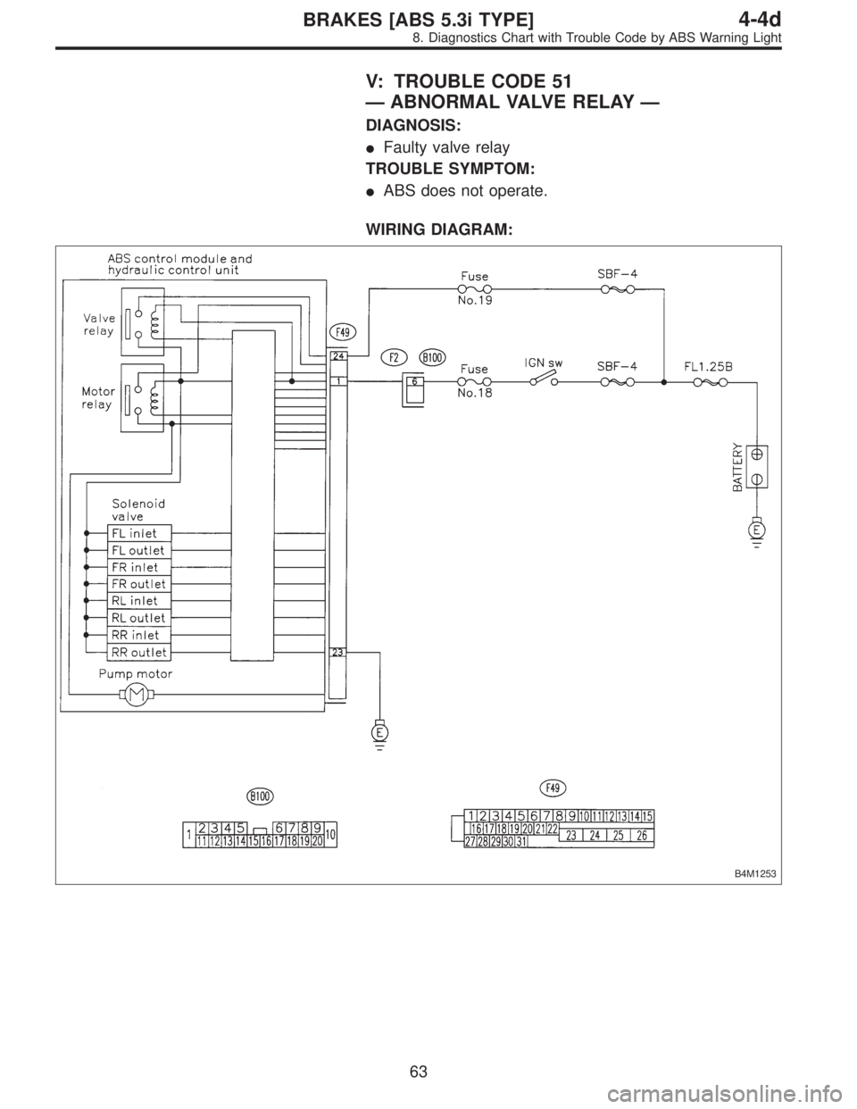
V: TROUBLE CODE 51
—ABNORMAL VALVE RELAY—
DIAGNOSIS:
�Faulty valve relay
TROUBLE SYMPTOM:
�ABS does not operate.
WIRING DIAGRAM:
B4M1253
63
4-4dBRAKES [ABS 5.3i TYPE]
8. Diagnostics Chart with Trouble Code by ABS Warning Light
Page 2940 of 3342
 Turn ignition switch to OFF.
2) Disconnect connector from ABSCM&H/U.
3) Run the engine at idle.
4) Measure voltage between ABSCM&H/U connector and
chas")
B4M1254A
8V1CHECK INPUT VOLTAGE OF
ABSCM&H/U.
1) Turn ignition switch to OFF.
2) Disconnect connector from ABSCM&H/U.
3) Run the engine at idle.
4) Measure voltage between ABSCM&H/U connector and
chassis ground.
Connector & terminal
(F49) No. 1 (+)—Chassis ground (�):
(F49) No. 24 (+)—Chassis ground (�):
: Is the voltage between 10 V and 15 V?
: Go to step8V2.
: Repair harness connector between battery and
ABSCM&H/U.
B4M1243A
8V2CHECK GROUND CIRCUIT OF
ABSCM&H/U.
1) Turn ignition switch to OFF.
2) Measure resistance between ABSCM&H/U connector
and chassis ground.
Connector & terminal
(F49) No. 23—Chassis ground:
: Is the resistance less than 0.5Ω?
: Go to step8V3.
: Repair ABSCM&H/U ground harness.
B4M1272A
8V3
CHECK VALVE RELAY IN ABSCM&H/U.
Measure resistance between ABSCM&H/U and terminals.
Terminals
No. 23 (+)—No. 24 (�):
: Is the resistance more than 1 MΩ?
: Go to step8V4.
: Replace ABSCM&H/U.
64
4-4dBRAKES [ABS 5.3i TYPE]
8. Diagnostics Chart with Trouble Code by ABS Warning Light
 Start engine.
2) Idling after warm-up.
3) Measure voltage between generator B terminal and
chassis ground.
Terminal
Generator B terminal—Chassis ground:
: Is the volt")
 Turn ignition switch to OFF.
2) Measure resistance between ABSCM&H/U connector
and chassis ground.
Connector & terminal
(F49) No. 23—Chassis ground:")

 Turn ignition switch to ON.
2) Measure voltage between ABSCM&H/U connector and
chassis ground.
Connector & terminal
(F49) No. 3 (+)—Chassis ground (�)")