Page 2960 of 3342
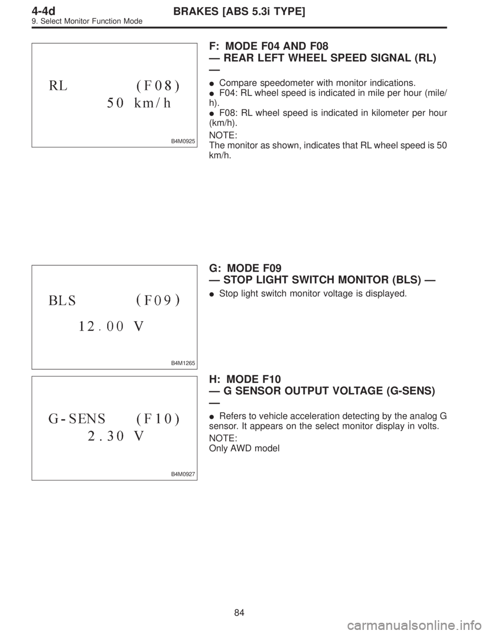
B4M0925
F: MODE F04 AND F08
—REAR LEFT WHEEL SPEED SIGNAL (RL)
—
�Compare speedometer with monitor indications.
�F04: RL wheel speed is indicated in mile per hour (mile/
h).
�F08: RL wheel speed is indicated in kilometer per hour
(km/h).
NOTE:
The monitor as shown, indicates that RL wheel speed is 50
km/h.
B4M1265
G: MODE F09
—STOP LIGHT SWITCH MONITOR (BLS)—
�Stop light switch monitor voltage is displayed.
B4M0927
H: MODE F10
—G SENSOR OUTPUT VOLTAGE (G-SENS)
—
�Refers to vehicle acceleration detecting by the analog G
sensor. It appears on the select monitor display in volts.
NOTE:
Only AWD model
84
4-4dBRAKES [ABS 5.3i TYPE]
9. Select Monitor Function Mode
Page 2961 of 3342
LED No. Signal name Display
1 Stop light switch B1
2 Valve relay signal VR
3 Motor relay signal MR
4 AT ABS signal AT
5——
6 ABS warning light AW
7 Valve relay monitor VM
8 Motor relay monitor MM
9 CCM signal CM
10——
B1 VR MR AT—
AW VM MM CM—
1
2345
678910
I: MODE FA0
—ON↔OFF SIGNAL—
Requirement for LED“ON”
LED No. 1 Stop light switch is turned ON. (With brake
pedal depressed.)
LED No. 2 Valve relay is turned OFF.
LED No. 3 Motor relay is turned ON.
LED No. 4 ABS control operates.
LED No. 6 ABS warning light is ON.
LED No. 7 Valve relay is turned OFF.
LED No. 8 Motor relay is turned ON.
LED No. 9 ABS control operates.
85
4-4dBRAKES [ABS 5.3i TYPE]
9. Select Monitor Function Mode
Page 2965 of 3342
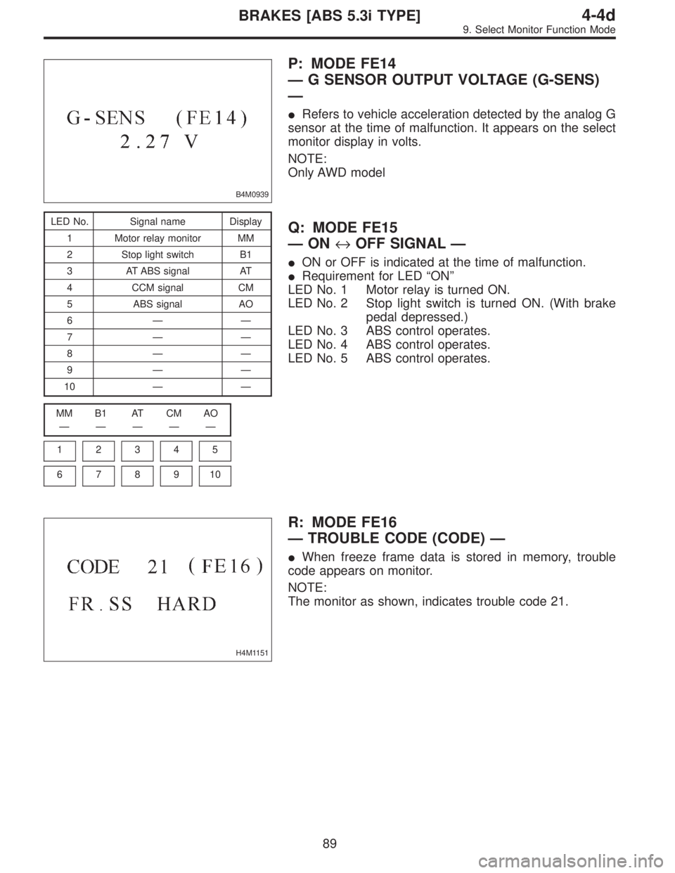
B4M0939
P: MODE FE14
—G SENSOR OUTPUT VOLTAGE (G-SENS)
—
�Refers to vehicle acceleration detected by the analog G
sensor at the time of malfunction. It appears on the select
monitor display in volts.
NOTE:
Only AWD model
LED No. Signal name Display
1 Motor relay monitor MM
2 Stop light switch B1
3 AT ABS signal AT
4 CCM signal CM
5 ABS signal AO
6——
7——
8——
9——
10——
MM B1 AT CM AO
—————
1
2345
678910
Q: MODE FE15
—ON↔OFF SIGNAL—
�ON or OFF is indicated at the time of malfunction.
�Requirement for LED“ON”
LED No. 1 Motor relay is turned ON.
LED No. 2 Stop light switch is turned ON. (With brake
pedal depressed.)
LED No. 3 ABS control operates.
LED No. 4 ABS control operates.
LED No. 5 ABS control operates.
H4M1151
R: MODE FE16
—TROUBLE CODE (CODE)—
�When freeze frame data is stored in memory, trouble
code appears on monitor.
NOTE:
The monitor as shown, indicates trouble code 21.
89
4-4dBRAKES [ABS 5.3i TYPE]
9. Select Monitor Function Mode
Page 2967 of 3342
![SUBARU LEGACY 1997 Service Repair Manual B: LIST OF TROUBLE CODE
Code Display screen (FB1) Contents of diagnosis Ref. to
—ERROR 3 (1) Select monitor communication failure 4-4d [T10C0]
11 NO TROUBLEAlthough no trouble appears on the select](/manual-img/17/57434/w960_57434-2966.png "SUBARU LEGACY 1997 Service Repair Manual B: LIST OF TROUBLE CODE
Code Display screen (FB1) Contents of diagnosis Ref. to
—ERROR 3 (1) Select monitor communication failure 4-4d [T10C0]
11 NO TROUBLEAlthough no trouble appears on the select")
B: LIST OF TROUBLE CODE
Code Display screen (FB1) Contents of diagnosis Ref. to
—ERROR 3 (1) Select monitor communication failure 4-4d [T10C0]
11 NO TROUBLEAlthough no trouble appears on the select monitor display, the ABS
warning light remains on.4-4d [T10D0]
21 FR. SS HARD Open circuit or input voltage too high of FR sensor 4-4d [T10E0]
22 FR. SS SOFT Abnormal ABS sensor signal of FR sensor 4-4d [T10I0]
23 FL. SS HARD Open circuit or input voltage too high of FL sensor 4-4d [T10F0]
24 FL. SS SOFT Abnormal ABS sensor signal of FL sensor 4-4d [T10J0]
25 RR. SS HARD Open circuit or input voltage too high of RR sensor 4-4d [T10G0]
26 RR. SS SOFT Abnormal ABS sensor signal of RR sensor 4-4d [T10K0]
27 RL. SS HARD Open circuit or input voltage too high of RL sensor 4-4d [T10H0]
28 RL. SS SOFT Abnormal ABS sensor signal of RL sensor 4-4d [T10L0]
29 EITHER. SS SOFT Abnormal ABS sensor signal (any one of four) 4-4d [T10M0]
31 FR. EV VALVE Abnormal FR inlet valve 4-4d [T10N0]
32 FR. AV VALVE Abnormal FR outlet valve 4-4d [T10R0]
33 FL. EV VALVE Abnormal FL inlet valve 4-4d [T10O0]
34 FL. AV VALVE Abnormal FL outlet valve 4-4d [T10S0]
35 RR. EV VALVE Abnormal RR inlet valve 4-4d [T10P0]
36 RR. AV VALVE Abnormal RR outlet valve 4-4d [T10T0]
37 RL. EV VALVE Abnormal RL inlet valve 4-4d [T10Q0]
38 RL. AV VALVE Abnormal RL outlet valve 4-4d [T10U0]
41 ECU Abnormal ABSCM&H/U 4-4d [T10V0]
42LOW VOLTAGE Source voltage is low. 4-4d [T10W0]
HIGH VOLTAGE Source voltage is high. 4-4d [T10X0]
44CCM LINE A combination of AT control abnormals (ABS not in control) 4-4d [T10Y0]
CCM OPEN A combination of AT control abnormals (ABS in control) 4-4d [T10Z0]
51V. RELAY Abnormal valve relay 4-4d [T10AA0]
V. RELAY ON Valve relay ON failure 4-4d [T10AB0]
52M. RELAY OPEN Open circuit of motor relay 4-4d [T10AC0]
M. RELAY ON Motor relay ON failure 4-4d [T10AD0]
MOTOR Abnormal motor 4-4d [T10AE0]
54 BLS Abnormal stop light switch 4-4d [T10AF0]
56G SENSOR LINE Open or short circuit of G sensor 4-4d [T10AG0]
G SENSOR +B Battery short of G sensor 4-4d [T10AH0]
G SENSOR H µ Abnormal G sensor high µ output 4-4d [T10AI0]
G SENSOR STICK G sensor output is stuck. 4-4d [T10AJ0]
NOTE:
High µ means high friction coefficient against road sur-
face.
91
4-4dBRAKES [ABS 5.3i TYPE]
10. Diagnostics Chart with Select Monitor
Page 2968 of 3342
B4M0943
C: ERROR 3 (1)
—SELECT MONITOR COMMUNICATION
FAILURE—
DIAGNOSIS:
�Faulty harness connector
TROUBLE SYMPTOM:
�ABS warning light remains on.
�ERROR 3 or 1 appears on the select monitor display.
WIRING DIAGRAM:
B4M1266
92
4-4dBRAKES [ABS 5.3i TYPE]
10. Diagnostics Chart with Select Monitor
Page 2972 of 3342
B4M0944
D: NO TROUBLE
—ALTHOUGH NO TROUBLE APPEARS ON
THE SELECT MONITOR DISPLAY, THE ABS
WARNING LIGHT REMAINS ON—
DIAGNOSIS:
�ABS warning light circuit is shorted.
TROUBLE SYMPTOM:
�ABS warning light remains on.
�NO TROUBLE displayed on the select monitor.
NOTE:
When the ABS warning light is OFF and“NO TROUBLE”
is displayed on the select monitor, the system is in normal
condition.
WIRING DIAGRAM:
B4M1230
96
4-4dBRAKES [ABS 5.3i TYPE]
10. Diagnostics Chart with Select Monitor
Page 2973 of 3342
 Turn ignition switch to OFF.
2) Disconnect connector (F2) from connector (B100).
3) Turn ignition switch to ON.
: Does the ABS warning light remain off?
: Go to step10D2.")
10D1
CHECK WIRING HARNESS.
1) Turn ignition switch to OFF.
2) Disconnect connector (F2) from connector (B100).
3) Turn ignition switch to ON.
: Does the ABS warning light remain off?
: Go to step10D2.
: Repair front wiring harness.
B4M1235A
10D2
CHECK PROJECTION AT ABSCM&H/U.
1) Turn ignition switch to OFF.
2) Disconnect connector from ABSCM&H/U.
3) Check for broken projection at the ABSCM&H/U termi-
nal.
: Are the projection broken?
: Go to step10D3.
: Replace ABSCM&H/U.
B4M1237A
10D3
CHECK ABSCM&H/U.
Measure resistance between ABSCM&H/U terminals.
Terminals
No. 21—No. 23:
: Is the resistance more than 1 MΩ?
: Go to step10D4.
: Replace valve relay.
B4M1236A
10D4
CHECK WIRING HARNESS.
Measure resistance between connector (F2) and chassis
ground.
Connector & terminal
(F2) No. 9—Chassis ground:
: Is the resistance less than 0.5Ω?
: Go to step10D5.
: Repair harness.
B4M1236A
10D5
CHECK WIRING HARNESS.
1) Connect connector to ABSCM&H/U.
2) Measure resistance between connector (F2) and chas-
sis ground.
Connector & terminal
(F2) No. 9—Chassis ground:
: Is the resistance more than 1 MΩ?
: Go to step10D6.
: Repair harness.
97
4-4dBRAKES [ABS 5.3i TYPE]
10. Diagnostics Chart with Select Monitor
Page 3037 of 3342
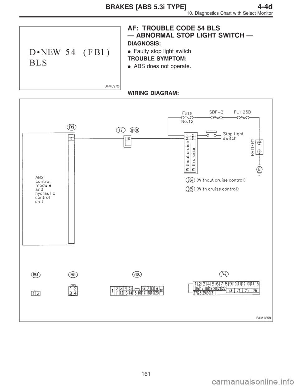
B4M0972
AF: TROUBLE CODE 54 BLS
—ABNORMAL STOP LIGHT SWITCH—
DIAGNOSIS:
�Faulty stop light switch
TROUBLE SYMPTOM:
�ABS does not operate.
WIRING DIAGRAM:
B4M1258
161
4-4dBRAKES [ABS 5.3i TYPE]
10. Diagnostics Chart with Select Monitor