Page 2120 of 3342
B2M1102
AZ: DTC P0462
—FUEL LEVEL SENSOR CIRCUIT LOW
INPUT—
DTC DETECTING CONDITION:
�Two consecutive driving cycles with fault
WIRING DIAGRAM:
B2M0933
CAUTION:
After repair or replacement of faulty parts, conduct
CLEAR MEMORY and INSPECTION MODES.
269
2-7ON-BOARD DIAGNOSTICS II SYSTEM
10. Diagnostic Chart with Trouble Code for LHD Vehicles
Page 2122 of 3342

1) Turn ignition switch to ON. (Engine OFF)
2) Measure voltage between ECM connector and chassis
ground.
: Co")
H2M1414B
10AZ3CHECK INPUT SIGNAL FOR ECM.
(USING VOLTAGE METER AND SUBARU
SELECT MONITOR.)
1) Turn ignition switch to ON. (Engine OFF)
2) Measure voltage between ECM connector and chassis
ground.
: Connector & terminal
(B84) No. 27 (+)—Chassis ground (�):
Is the voltage less than 0.12 V?
: Go to step10AZ4.
: Go to next.
H2M1327
: Does the value change less than 0.12 V by
shaking harness and connector of ECM
while monitoring the value with Subaru
Select Monitor?
�Subaru Select Monitor
Designate mode using function key.
Function mode: F45
�F45: Fuel level sensor output signal is indicated.
: Repair poor contact in ECM connector.
: Even if MIL lights up, the circuit has returned to a
normal condition at this time. A temporary poor
contact of the connector may be the cause.
NOTE:
In this case, repair the following:
�Poor contact in fuel pump connector
�Poor contact in combination meter connector
�Poor contact in ECM connector
�Poor contact in coupling connector (i3, B99, B22, B98
and R57)
G2M0340
10AZ4CHECK HARNESS BETWEEN ECM, COM-
BINATION METER AND FUEL PUMP
CONNECTOR.
1) Turn ignition switch to OFF.
2) Remove fuel pump access hole lid located on the right
rear of trunk compartment floor (Sedan) or luggage com-
partment floor (Wagon).
271
2-7ON-BOARD DIAGNOSTICS II SYSTEM
10. Diagnostic Chart with Trouble Code for LHD Vehicles
Page 2126 of 3342
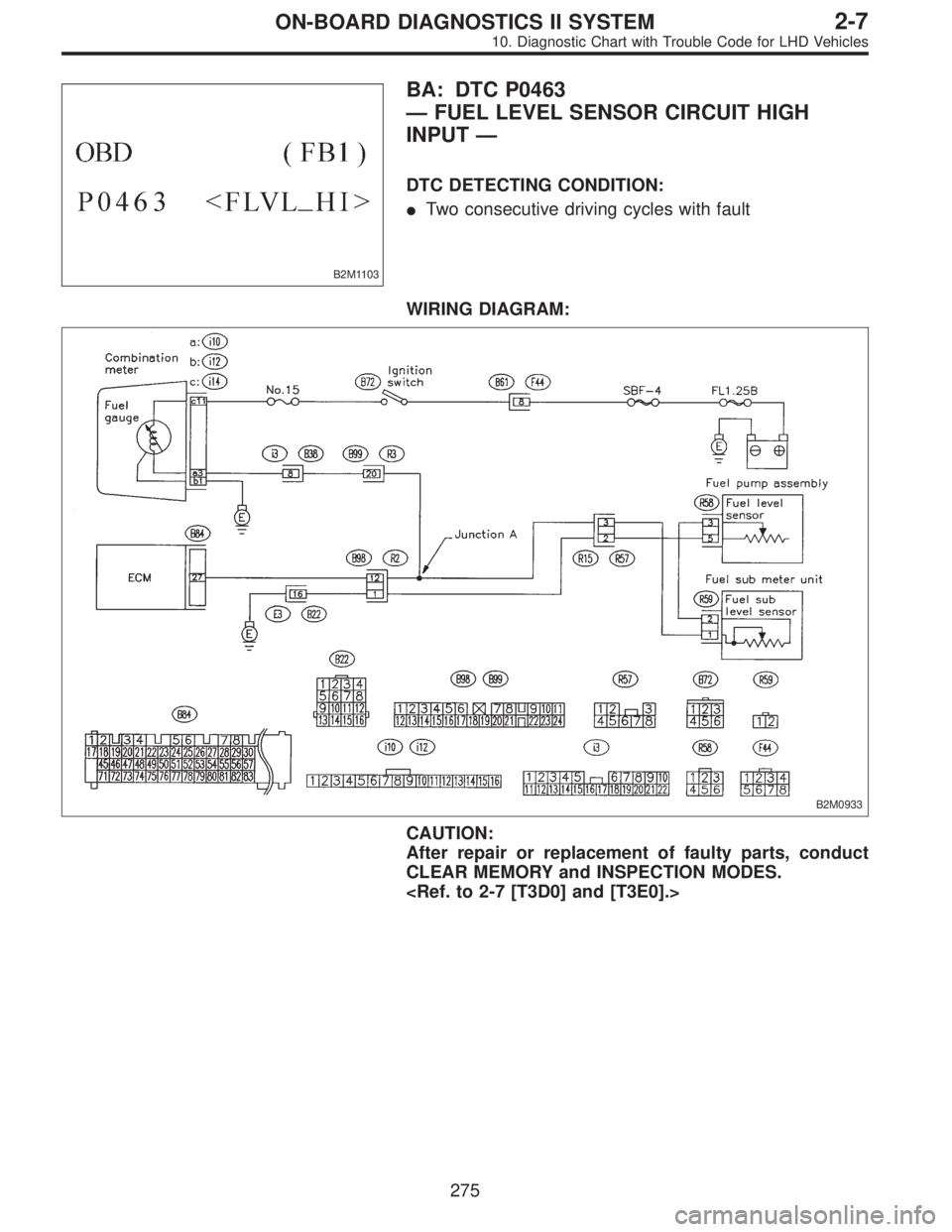
B2M1103
BA: DTC P0463
—FUEL LEVEL SENSOR CIRCUIT HIGH
INPUT—
DTC DETECTING CONDITION:
�Two consecutive driving cycles with fault
WIRING DIAGRAM:
B2M0933
CAUTION:
After repair or replacement of faulty parts, conduct
CLEAR MEMORY and INSPECTION MODES.
275
2-7ON-BOARD DIAGNOSTICS II SYSTEM
10. Diagnostic Chart with Trouble Code for LHD Vehicles
Page 2128 of 3342

1) Turn ignition switch to ON. (Engine OFF)
2) Measure voltage between ECM connector and chassis
ground.
: Co")
H2M1414B
10BA3CHECK INPUT SIGNAL FOR ECM.
(USING VOLTAGE METER AND SUBARU
SELECT MONITOR.)
1) Turn ignition switch to ON. (Engine OFF)
2) Measure voltage between ECM connector and chassis
ground.
: Connector & terminal
(B84) No. 27 (+)—Chassis ground (�):
Is the voltage more than 4.75 V?
: Go to step10BA4.
: Even if MIL lights up, the circuit has returned to a
normal condition at this time. A temporary poor
contact of the connector may be the cause.
NOTE:
In this case, repair the following:
�Poor contact in fuel pump connector
�Poor contact in combination meter connector
�Poor contact in ECM connector
�Poor contact in coupling connector (i3, B99, B22, B98
and R57)
G2M0340
10BA4
CHECK FUEL LEVEL SENSOR.
1) Turn ignition switch to OFF.
2) Remove fuel pump access hole lid located on the right
rear of trunk compartment floor (Sedan) or luggage com-
partment floor (Wagon).
B2M0935
3) Disconnect connector from fuel pump.
4) Measure resistance between connector terminals of
fuel pump.
: Terminals
No. 3—No. 5:
Is the resistance less than 100Ω?
: Go to step10BA5.
: Replace fuel sending unit.
G2M0863
10BA5
CHECK FUEL SUB LEVEL SENSOR.
1) Remove service hole cover located on the left rear of
trunk compartment floor (Sedan) or luggage compartment
floor (Wagon).
277
2-7ON-BOARD DIAGNOSTICS II SYSTEM
10. Diagnostic Chart with Trouble Code for LHD Vehicles
Page 2130 of 3342
 No. 5—Chassis ground:
Is the res")
B2M0938A
10BA7CHECK GROUND CIRCUIT OF FUEL
LEVEL SENSOR.
Measure resistance of harness between fuel pump con-
nector and chassis ground.
: Connector & terminal
(R58) No. 5—Chassis ground:
Is the resistance less than 5Ω?
: Go to step10BA8.
: Repair harness and connector.
NOTE:
In this case, repair the following:
�Open circuit in harness between fuel pump connector
and chassis grounding terminal
�Poor contact in fuel pump connector
�Poor contact in coupling connectors (R57, B98 and B22)
B2M0939A
10BA8CHECK HARNESS BETWEEN ECM AND
FUEL PUMP CONNECTOR.
1) Connect connector to fuel sub meter unit.
2) Turn ignition switch to ON.
3) Measure voltage between fuel pump connector and
chassis ground.
: Connector & terminal
(R58) No. 3 (+)—Chassis ground (�):
Is the voltage less than 1 V?
: Repair harness and connector.
NOTE:
In this case, repair the following:
�Open circuit in harness between fuel pump connector
and junction A on rear wiring harness
�Poor contact in fuel sub meter unit connector
�Poor contact in fuel pump connector
�Poor contact in coupling connector (R57)
: Go to next step 4).
279
2-7ON-BOARD DIAGNOSTICS II SYSTEM
10. Diagnostic Chart with Trouble Code for LHD Vehicles
Page 2132 of 3342
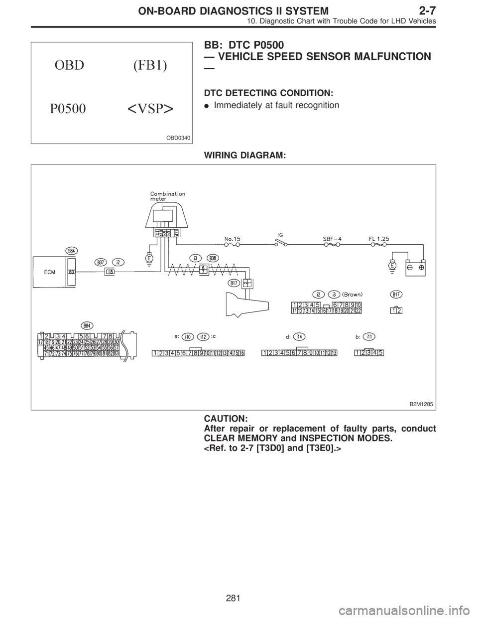
OBD0340
BB: DTC P0500
—VEHICLE SPEED SENSOR MALFUNCTION
—
DTC DETECTING CONDITION:
�Immediately at fault recognition
WIRING DIAGRAM:
B2M1285
CAUTION:
After repair or replacement of faulty parts, conduct
CLEAR MEMORY and INSPECTION MODES.
281
2-7ON-BOARD DIAGNOSTICS II SYSTEM
10. Diagnostic Chart with Trouble Code for LHD Vehicles
Page 2133 of 3342
![SUBARU LEGACY 1997 Service Repair Manual 10BB1CHECK SPEEDOMETER OPERATION IN
COMBINATION METER.
: Does speedometer operate normally?
: Go to step10BB2.
: Check speedometer and vehicle speed sensor
<Ref. to 6-2 [K3A0].>.
B2M0573A
10BB2CHECK H](/manual-img/17/57434/w960_57434-2132.png "SUBARU LEGACY 1997 Service Repair Manual 10BB1CHECK SPEEDOMETER OPERATION IN
COMBINATION METER.
: Does speedometer operate normally?
: Go to step10BB2.
: Check speedometer and vehicle speed sensor
<Ref. to 6-2 [K3A0].>.
B2M0573A
10BB2CHECK H")
10BB1CHECK SPEEDOMETER OPERATION IN
COMBINATION METER.
: Does speedometer operate normally?
: Go to step10BB2.
: Check speedometer and vehicle speed sensor
.
B2M0573A
10BB2CHECK HARNESS BETWEEN ECM AND
COMBINATION METER CONNECTOR.
1) Turn ignition switch to OFF.
2) Disconnect connector from TCM.
3) Turn ignition switch to ON.
4) Measure voltage between ECM and chassis ground.
: Connector & terminal
(B84) No. 83 (+)—Chassis ground (�):
Is the voltage more than 2 V?
: Repair harness and connector.
NOTE:
In this case, repair the following:
�Open circuit in harness between ECM and combination
meter connector
�Poor contact in ECM connector
�Poor contact in combination meter connector
�Poor contact in coupling connector (B37)
: Go to step10BB3.
B2M0574A
10BB3CHECK HARNESS BETWEEN ECM AND
COMBINATION METER CONNECTOR.
1) Turn ignition switch to OFF.
2) Disconnect connector from ECM.
3) Measure resistance of harness between ECM connec-
tor and chassis ground.
: Connector & terminal
(B84) No. 83—Chassis ground:
Is the resistance less than 10Ω?
: Repair ground short circuit in harness between
ECM and combination meter connector.
: Repair poor contact in ECM connector.
282
2-7ON-BOARD DIAGNOSTICS II SYSTEM
10. Diagnostic Chart with Trouble Code for LHD Vehicles
Page 2150 of 3342
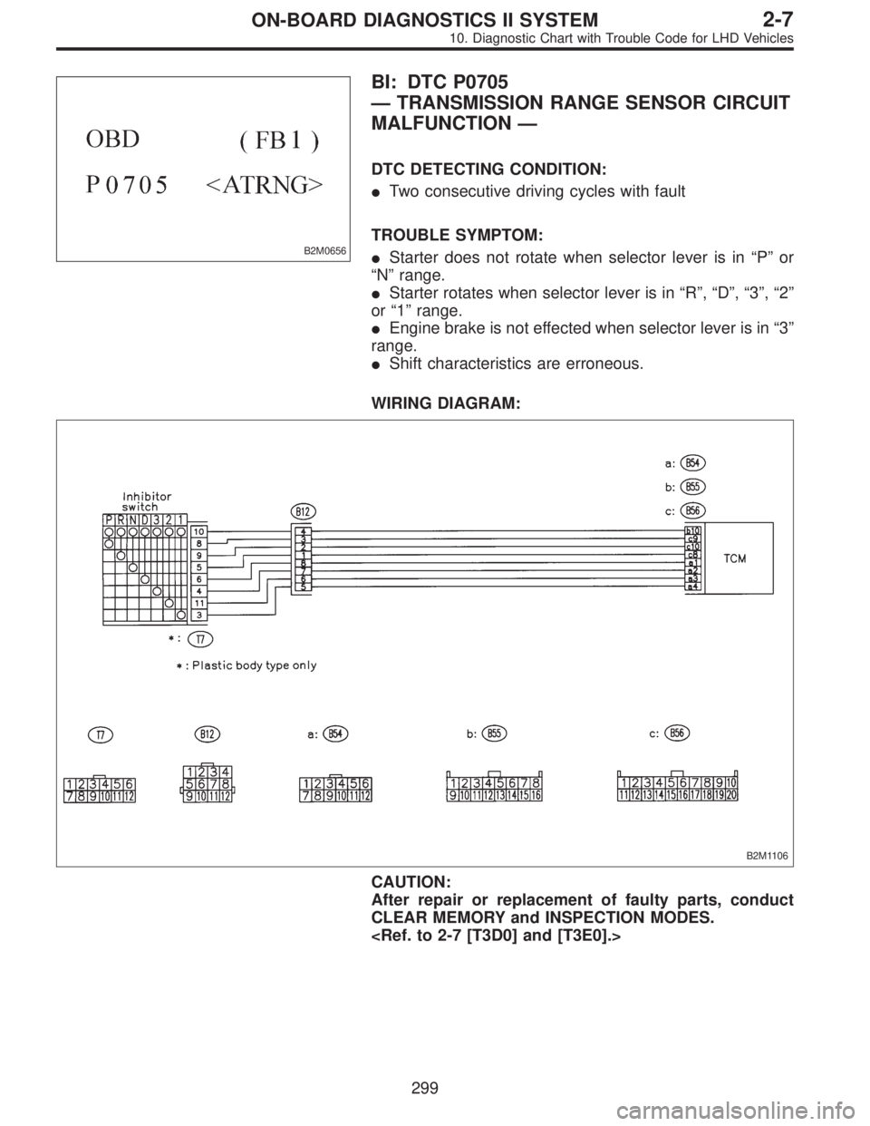
B2M0656
BI: DTC P0705
—TRANSMISSION RANGE SENSOR CIRCUIT
MALFUNCTION—
DTC DETECTING CONDITION:
�Two consecutive driving cycles with fault
TROUBLE SYMPTOM:
�Starter does not rotate when selector lever is in“P”or
“N”range.
�Starter rotates when selector lever is in“R”,“D”,“3”,“2”
or“1”range.
�Engine brake is not effected when selector lever is in“3”
range.
�Shift characteristics are erroneous.
WIRING DIAGRAM:
B2M1106
CAUTION:
After repair or replacement of faulty parts, conduct
CLEAR MEMORY and INSPECTION MODES.
299
2-7ON-BOARD DIAGNOSTICS II SYSTEM
10. Diagnostic Chart with Trouble Code for LHD Vehicles