Page 1384 of 3342
11) Operate FRO (Front Right Outlet) valve and RLO
(Rear Left Outlet) valve to bleed air from hydraulic unit
outlet circuit.
(1) Press TCS OFF switch while depressing brake
pedal.
(2) Make sure ABS warning light illuminates.
(3) Repeatedly depress and release brake pedal 10
times or more while pressing TCS OFF switch.
NOTE:
�Air comes out from reservoir tank.
12) Operate FLO (Front Left Outlet) valve and RRO (Rear
Right Outlet) valve to bleed air from hydraulic unit outlet
circuit.
(1) Press TCS OFF switch while depressing brake
pedal.
(2) Make sure TCS warning light illuminates.
(3) Repeatedly depress and release brake pedal 10
times or more while pressing TCS OFF switch.
NOTE:
�Air comes out from reservoir tank.
�The operations in steps 11) and 12) above can be
switched with each other by operating brake pedal (stop
light switch) while pressing TCS OFF switch.
�Repeat procedures 11) and 12) until air no longer comes
out of reservoir tank.
13) Perform these steps for the brakes connecting to the
secondary chamber of master cylinder, first, and then for
the ones connecting to primary chamber. With all proce-
dures completed, fully depress the brake pedal and keep
it in that position for approximately 20 seconds to make
sure that there is no leak evident in the entire system.
14) Turn ignition switch OFF.
15) Perform TCS sequence control.
[W20F0].>
100
4-4SERVICE PROCEDURE
19. Air Bleeding (With TCS model)
Page 1386 of 3342
3. CONDITIONS FOR COMPLETION OF AIR
BLEEDING CONTROL
When any of the following conditions occurs, ABS and TCS
warning lights illuminate. Air bleeding control stops, while
the ABS and TCS function will then stop. The brake sys-
tem functions as a conventional brake system.
1) When the speed of at least one wheel reaches 10 km/h
(6 MPH).
2) When terminal No. 4 is separated from diagnosis termi-
nal. (When select monitor is not used.)
3) When pump motor remains ON for two minutes.
4) When TCS valve remains open for two minutes.
5) When outlet valve remains closed for two minutes.
6) When malfunction is detected.
NOTE:
When a malfunction is detected the air bleeding operation
stops and the trouble codes are stored in memory.
B4M0082C
C: AIR BLEEDING CONTROL WITH
DIAGNOSIS CONNECTOR
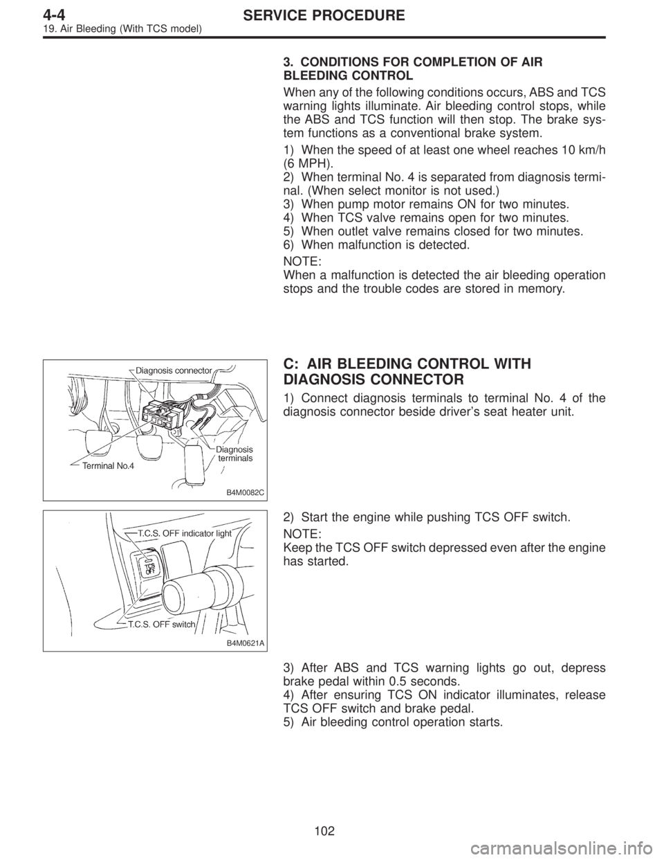
1) Connect diagnosis terminals to terminal No. 4 of the
diagnosis connector beside driver’s seat heater unit.
B4M0621A
2) Start the engine while pushing TCS OFF switch.
NOTE:
Keep the TCS OFF switch depressed even after the engine
has started.
3) After ABS and TCS warning lights go out, depress
brake pedal within 0.5 seconds.
4) After ensuring TCS ON indicator illuminates, release
TCS OFF switch and brake pedal.
5) Air bleeding control operation starts.
102
4-4SERVICE PROCEDURE
19. Air Bleeding (With TCS model)
Page 1393 of 3342
D: ABS SEQUENCE CONTROL
1) Under the ABS sequence control, after the hydraulic
unit solenoid valve is driven, the operation of the hydraulic
unit can be checked by means of the brake tester or pres-
sure gauge.
2) ABS sequence control can be started by diagnosis con-
nector or select monitor.
B4M0082C
1. OPERATIONAL GUIDELINES OF THE ABS
SEQUENCE CONTROL WITH DIAGNOSIS
CONNECTOR
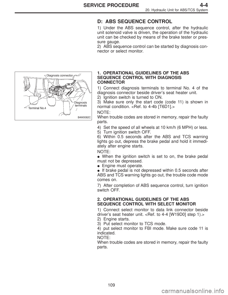
1) Connect diagnosis terminals to terminal No. 4 of the
diagnosis connector beside driver’s seat heater unit.
2) Ignition switch is turned to ON.
3) Make sure only the start code (code 11) is shown in
normal condition.
NOTE:
When trouble codes are stored in memory, repair the faulty
parts.
4) Set the speed of all wheels at 10 km/h (6 MPH) or less.
5) Turn ignition switch OFF.
6) Within 0.5 seconds after the ABS and TCS warning
lights go out, depress the brake pedal and hold it immedi-
ately after engine starts.
NOTE:
�When the ignition switch is set to on, the brake pedal
must not be depressed.
�Engine must operate.
�If brake pedal is not depressed within 0.5 seconds after
ABS and TCS warning lights go out, the trouble code mode
comes on.
7) After completion of ABS sequence control, turn ignition
switch OFF.
2. OPERATIONAL GUIDELINES OF THE ABS
SEQUENCE CONTROL WITH SELECT MONITOR
1) Connect select monitor to data link connector beside
driver’s seat heater unit.
2) Engine starts.
3) Put select monitor to TCS mode.
4) put select monitor to FBI mode. Make sure code 11 is
indicated.
NOTE:
When trouble codes are stored in memory, repair the faulty
parts.
109
4-4SERVICE PROCEDURE
20. Hydraulic Unit for ABS/TCS System
Page 1399 of 3342
F: TCS SEQUENCE CONTROL
1) Under the TCS sequence control, after the hydraulic
unit solenoid valve is driven, the operation of the hydraulic
unit can be checked by means of the brake tester or pres-
sure gauge.
2) TCS sequence control can be started by diagnosis con-
nector or select monitor.
B4M0082C
1. OPERATIONAL GUIDELINES OF THE TCS
SEQUENCE CONTROL WITH DIAGNOSIS
CONNECTOR
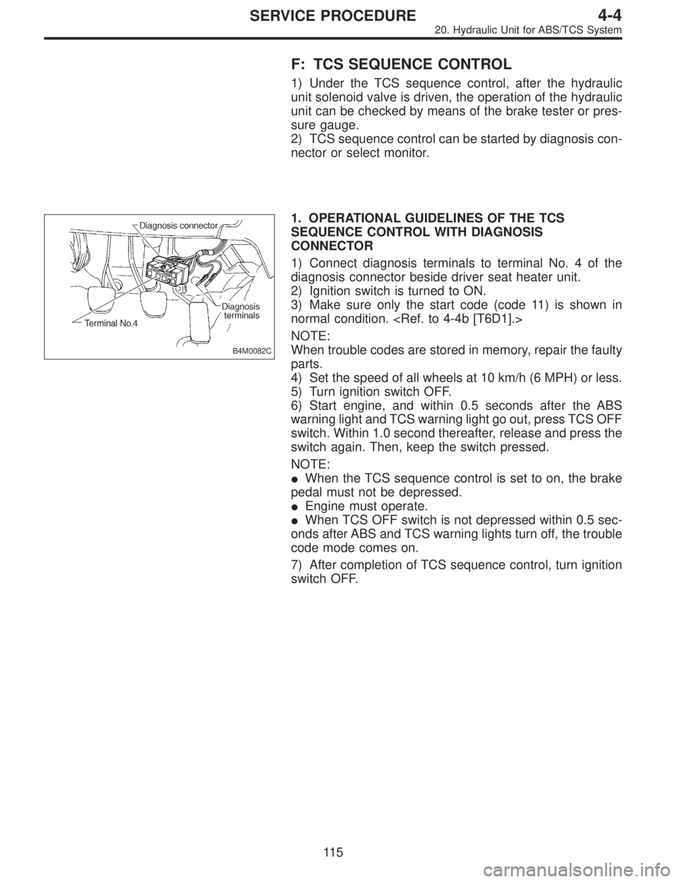
1) Connect diagnosis terminals to terminal No. 4 of the
diagnosis connector beside driver seat heater unit.
2) Ignition switch is turned to ON.
3) Make sure only the start code (code 11) is shown in
normal condition.
NOTE:
When trouble codes are stored in memory, repair the faulty
parts.
4) Set the speed of all wheels at 10 km/h (6 MPH) or less.
5) Turn ignition switch OFF.
6) Start engine, and within 0.5 seconds after the ABS
warning light and TCS warning light go out, press TCS OFF
switch. Within 1.0 second thereafter, release and press the
switch again. Then, keep the switch pressed.
NOTE:
�When the TCS sequence control is set to on, the brake
pedal must not be depressed.
�Engine must operate.
�When TCS OFF switch is not depressed within 0.5 sec-
onds after ABS and TCS warning lights turn off, the trouble
code mode comes on.
7) After completion of TCS sequence control, turn ignition
switch OFF.
11 5
4-4SERVICE PROCEDURE
20. Hydraulic Unit for ABS/TCS System
Page 1411 of 3342
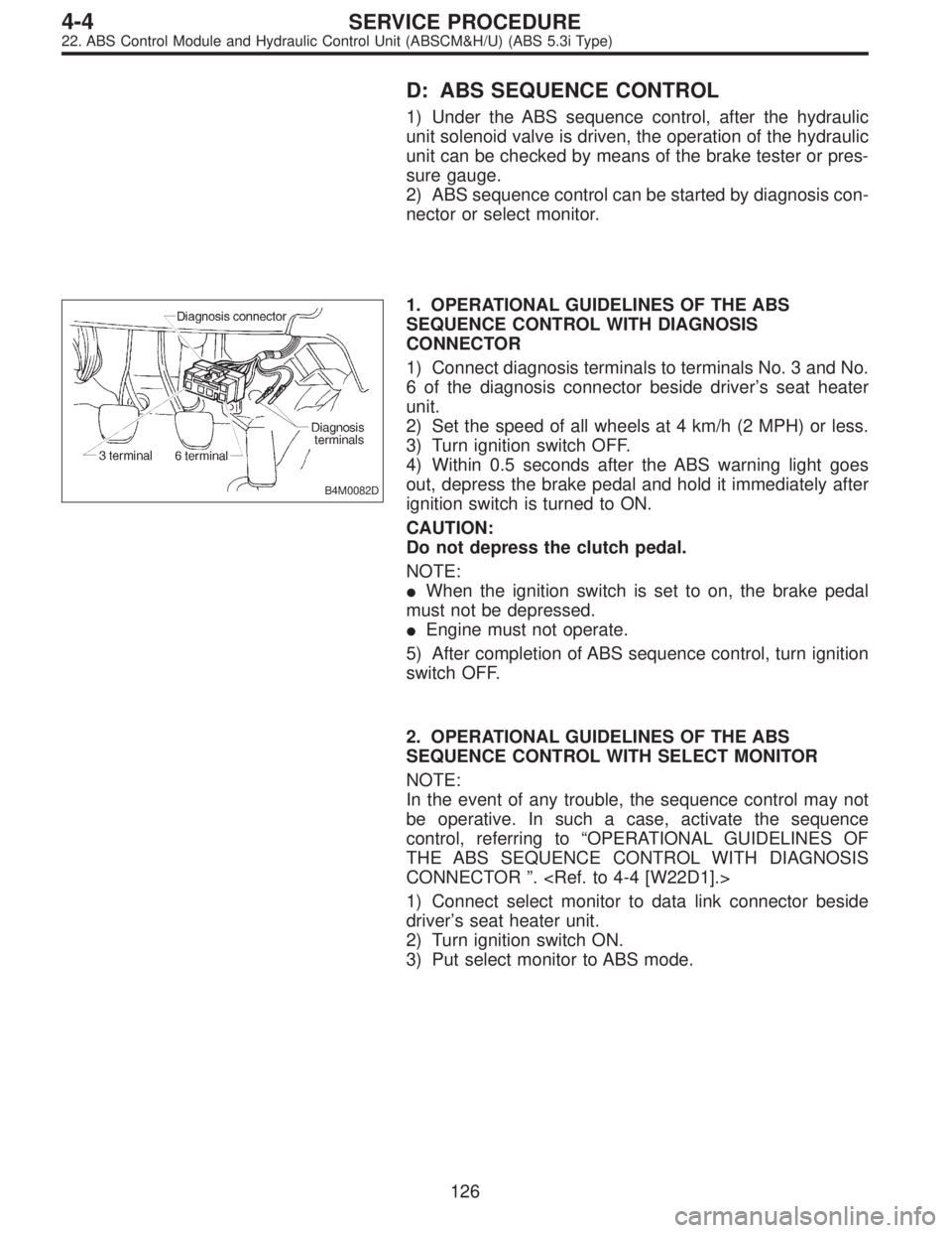
D: ABS SEQUENCE CONTROL
1) Under the ABS sequence control, after the hydraulic
unit solenoid valve is driven, the operation of the hydraulic
unit can be checked by means of the brake tester or pres-
sure gauge.
2) ABS sequence control can be started by diagnosis con-
nector or select monitor.
B4M0082D
1. OPERATIONAL GUIDELINES OF THE ABS
SEQUENCE CONTROL WITH DIAGNOSIS
CONNECTOR
1) Connect diagnosis terminals to terminals No. 3 and No.
6 of the diagnosis connector beside driver’s seat heater
unit.
2) Set the speed of all wheels at 4 km/h (2 MPH) or less.
3) Turn ignition switch OFF.
4) Within 0.5 seconds after the ABS warning light goes
out, depress the brake pedal and hold it immediately after
ignition switch is turned to ON.
CAUTION:
Do not depress the clutch pedal.
NOTE:
�When the ignition switch is set to on, the brake pedal
must not be depressed.
�Engine must not operate.
5) After completion of ABS sequence control, turn ignition
switch OFF.
2. OPERATIONAL GUIDELINES OF THE ABS
SEQUENCE CONTROL WITH SELECT MONITOR
NOTE:
In the event of any trouble, the sequence control may not
be operative. In such a case, activate the sequence
control, referring to“OPERATIONAL GUIDELINES OF
THE ABS SEQUENCE CONTROL WITH DIAGNOSIS
CONNECTOR”.
1) Connect select monitor to data link connector beside
driver’s seat heater unit.
2) Turn ignition switch ON.
3) Put select monitor to ABS mode.
126
4-4SERVICE PROCEDURE
22. ABS Control Module and Hydraulic Control Unit (ABSCM&H/U) (ABS 5.3i Type)
Page 1413 of 3342
B4M1030
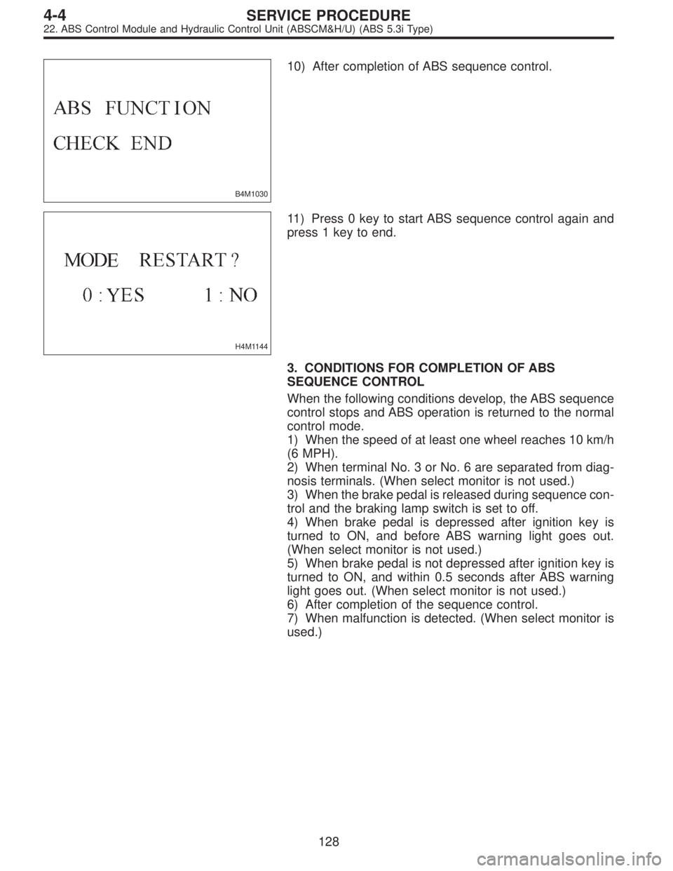
10) After completion of ABS sequence control.
H4M1144
11) Press 0 key to start ABS sequence control again and
press 1 key to end.
3. CONDITIONS FOR COMPLETION OF ABS
SEQUENCE CONTROL
When the following conditions develop, the ABS sequence
control stops and ABS operation is returned to the normal
control mode.
1) When the speed of at least one wheel reaches 10 km/h
(6 MPH).
2) When terminal No. 3 or No. 6 are separated from diag-
nosis terminals. (When select monitor is not used.)
3) When the brake pedal is released during sequence con-
trol and the braking lamp switch is set to off.
4) When brake pedal is depressed after ignition key is
turned to ON, and before ABS warning light goes out.
(When select monitor is not used.)
5) When brake pedal is not depressed after ignition key is
turned to ON, and within 0.5 seconds after ABS warning
light goes out. (When select monitor is not used.)
6) After completion of the sequence control.
7) When malfunction is detected. (When select monitor is
used.)
128
4-4SERVICE PROCEDURE
22. ABS Control Module and Hydraulic Control Unit (ABSCM&H/U) (ABS 5.3i Type)
Page 1428 of 3342
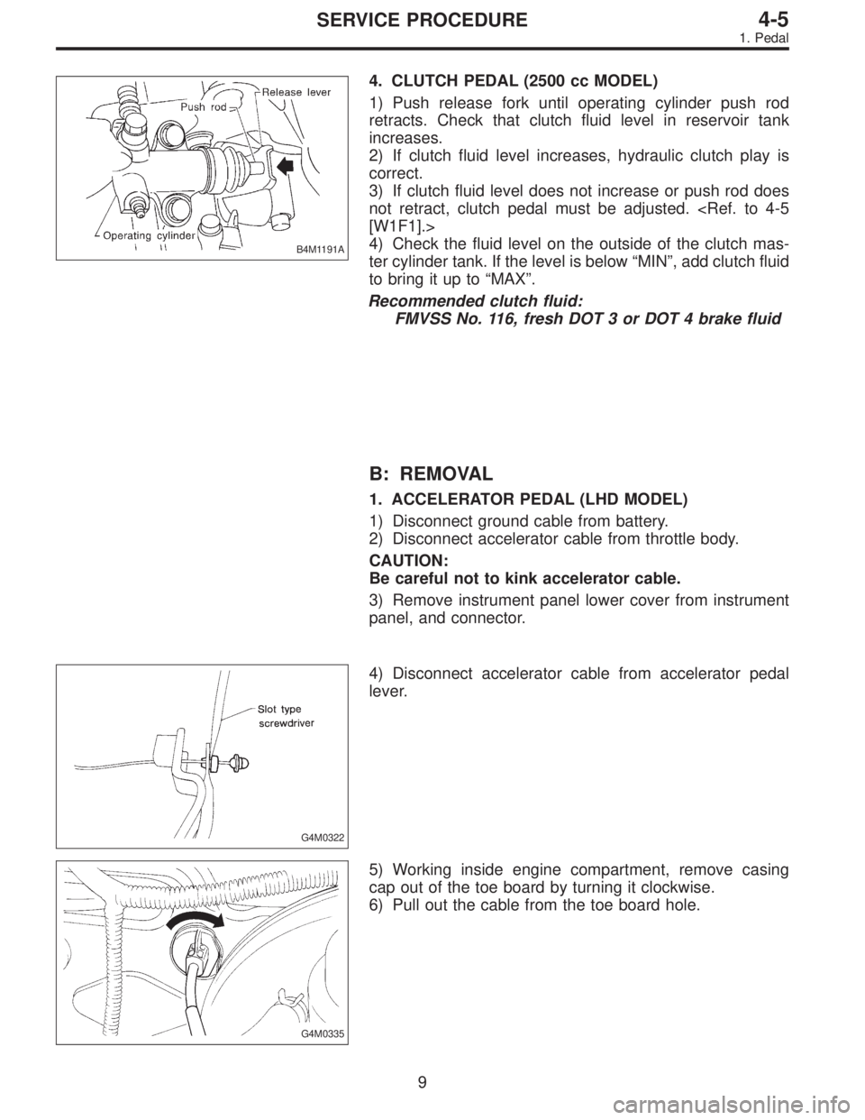
B4M1191A
4. CLUTCH PEDAL (2500 cc MODEL)
1) Push release fork until operating cylinder push rod
retracts. Check that clutch fluid level in reservoir tank
increases.
2) If clutch fluid level increases, hydraulic clutch play is
correct.
3) If clutch fluid level does not increase or push rod does
not retract, clutch pedal must be adjusted.
[W1F1].>
4) Check the fluid level on the outside of the clutch mas-
ter cylinder tank. If the level is below“MIN”, add clutch fluid
to bring it up to“MAX”.
Recommended clutch fluid:
FMVSS No. 116, fresh DOT 3 or DOT 4 brake fluid
B: REMOVAL
1. ACCELERATOR PEDAL (LHD MODEL)
1) Disconnect ground cable from battery.
2) Disconnect accelerator cable from throttle body.
CAUTION:
Be careful not to kink accelerator cable.
3) Remove instrument panel lower cover from instrument
panel, and connector.
G4M0322
4) Disconnect accelerator cable from accelerator pedal
lever.
G4M0335
5) Working inside engine compartment, remove casing
cap out of the toe board by turning it clockwise.
6) Pull out the cable from the toe board hole.
9
4-5SERVICE PROCEDURE
1. Pedal
Page 1617 of 3342
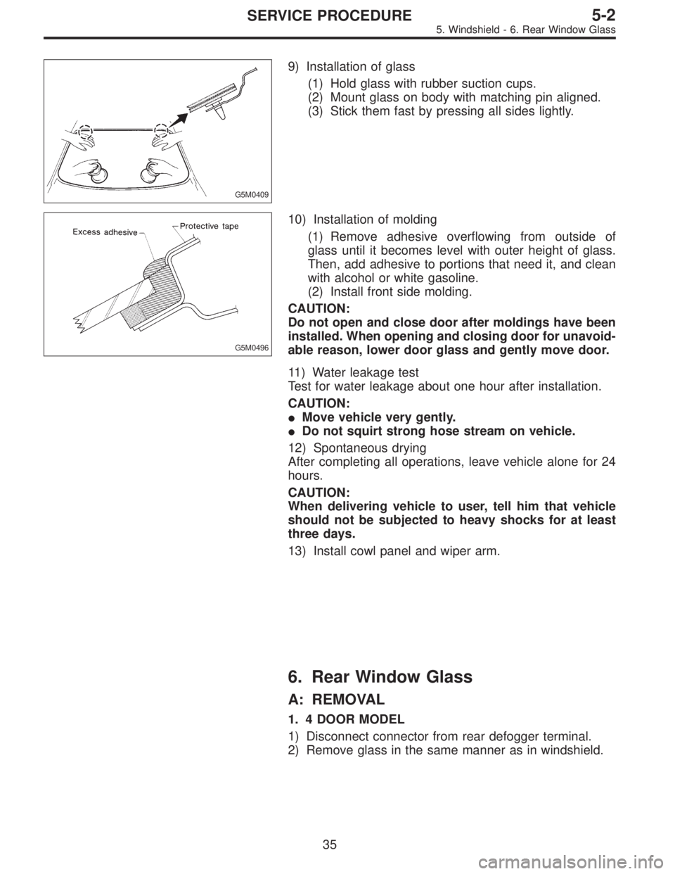
G5M0409
9) Installation of glass
(1) Hold glass with rubber suction cups.
(2) Mount glass on body with matching pin aligned.
(3) Stick them fast by pressing all sides lightly.
G5M0496
10) Installation of molding
(1) Remove adhesive overflowing from outside of
glass until it becomes level with outer height of glass.
Then, add adhesive to portions that need it, and clean
with alcohol or white gasoline.
(2) Install front side molding.
CAUTION:
Do not open and close door after moldings have been
installed. When opening and closing door for unavoid-
able reason, lower door glass and gently move door.
11) Water leakage test
Test for water leakage about one hour after installation.
CAUTION:
�Move vehicle very gently.
�Do not squirt strong hose stream on vehicle.
12) Spontaneous drying
After completing all operations, leave vehicle alone for 24
hours.
CAUTION:
When delivering vehicle to user, tell him that vehicle
should not be subjected to heavy shocks for at least
three days.
13) Install cowl panel and wiper arm.
6. Rear Window Glass
A: REMOVAL
1. 4 DOOR MODEL
1) Disconnect connector from rear defogger terminal.
2) Remove glass in the same manner as in windshield.
35
5-2SERVICE PROCEDURE
5. Windshield - 6. Rear Window Glass