Page 1241 of 3342
G4M0833
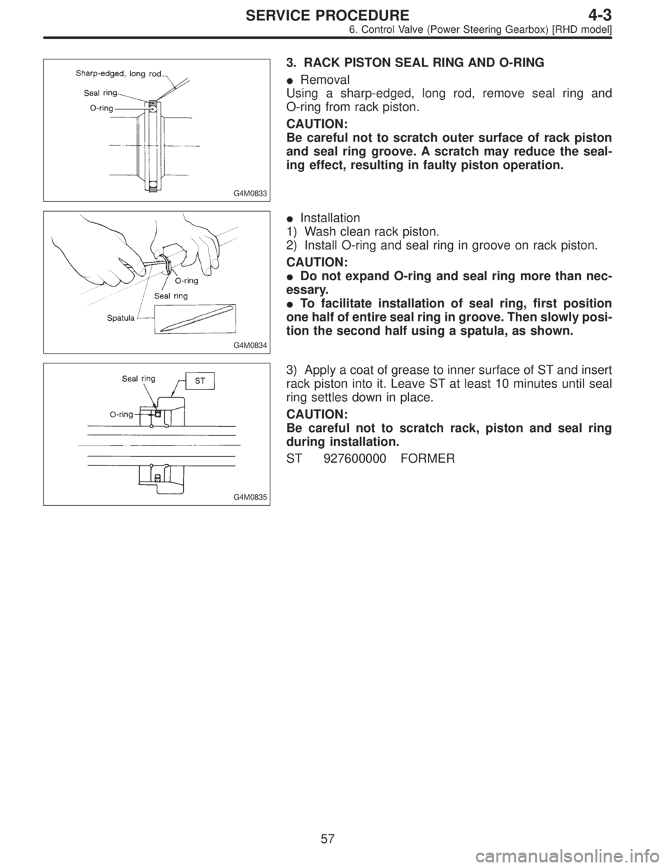
3. RACK PISTON SEAL RING AND O-RING
�Removal
Using a sharp-edged, long rod, remove seal ring and
O-ring from rack piston.
CAUTION:
Be careful not to scratch outer surface of rack piston
and seal ring groove. A scratch may reduce the seal-
ing effect, resulting in faulty piston operation.
G4M0834
�Installation
1) Wash clean rack piston.
2) Install O-ring and seal ring in groove on rack piston.
CAUTION:
�Do not expand O-ring and seal ring more than nec-
essary.
�To facilitate installation of seal ring, first position
one half of entire seal ring in groove. Then slowly posi-
tion the second half using a spatula, as shown.
G4M0835
3) Apply a coat of grease to inner surface of ST and insert
rack piston into it. Leave ST at least 10 minutes until seal
ring settles down in place.
CAUTION:
Be careful not to scratch rack, piston and seal ring
during installation.
ST 927600000 FORMER
57
4-3SERVICE PROCEDURE
6. Control Valve (Power Steering Gearbox) [RHD model]
Page 1295 of 3342
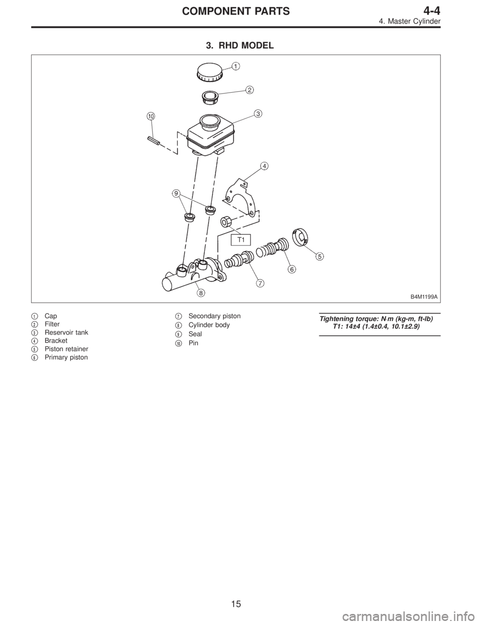
3. RHD MODEL
B4M1199A
�1Cap
�
2Filter
�
3Reservoir tank
�
4Bracket
�
5Piston retainer
�
6Primary piston�
7Secondary piston
�
8Cylinder body
�
9Seal
�
10Pin
Tightening torque: N⋅m (kg-m, ft-lb)
T1: 14±4 (1.4±0.4, 10.1±2.9)
15
4-4COMPONENT PARTS
4. Master Cylinder
Page 1349 of 3342

A: GENERAL RULES FOR EFFECTIVE
BLEEDING
1) Start with the brakes (wheels) connecting to the sec-
ondary chamber of the master cylinder.
2) The time interval betwee")
11. Air Bleeding (Without TCS model)
A: GENERAL RULES FOR EFFECTIVE
BLEEDING
1) Start with the brakes (wheels) connecting to the sec-
ondary chamber of the master cylinder.
2) The time interval between two brake pedal operations
(from the time when the pedal is released to the time when
it is depressed another time) shall be approximately 3 sec-
onds.
3) The air bleeder on each brake shall be released for 1
to 2 seconds.
B: BLEEDING PROCEDURE
CAUTION:
�The FMVSS No. 116, fresh DOT3 or 4 brake fluid
must be used.
�Cover bleeder with waste cloth, when loosening it,
to prevent brake fluid from being splashed over sur-
rounding parts.
�Avoid mixing different brands of brake fluid to pre-
vent degrading the quality of the fluid.
�Be careful not to allow dirt or dust to get into the
reservoir tank.
NOTE:
�During bleeding operation, keep the brake reserve tank
filled with brake fluid to eliminate entry of air.
�Brake pedal operating must be very slow.
�For convenience and safety, it is advisable to have two
man working.
G4M0434
G4M0435
1) Make sure that there is no leak from joints and connec-
tions of the brake system.
2) Fit one end of vinyl tube into the air bleeder and put the
other end into a brake fluid container.
3) Slowly depress the brake pedal and keep it depressed.
Then, open the air bleeder to discharge air together with
the fluid.
Release air bleeder for 1 to 2 seconds.
Next, with the bleeder closed, slowly release the brake
pedal.
Repeat these steps until there are no more air bubbles in
the vinyl tube.
Allow 3 to 4 seconds between two brake pedal operations.
CAUTION:
Cover bleeder with waste cloth, when loosening it, to
prevent brake fluid from being splashed over sur-
rounding parts.
NOTE:
Brake pedal operating must be very slow.
4) Tighten air bleeder securely when no air bubbles are
visible.
67
4-4SERVICE PROCEDURE
11. Air Bleeding (Without TCS model)
Page 1350 of 3342

5) Perform these steps for the brakes connecting to the
secondary chamber of master cylinder, first, and then for
the ones con")
Air bleeder tightening torque:
8±1 N⋅m (0.8±0.1 kg-m, 5.8±0.7 ft-lb)
5) Perform these steps for the brakes connecting to the
secondary chamber of master cylinder, first, and then for
the ones connecting to primary chamber. With all proce-
dures completed, fully depress the brake pedal and keep
it in that position for approximately 20 seconds to make
sure that there is no leak evident in the entire system.
G4M0436
6) Perform sequence control. (With ABS model)
4-4 [W15C1].>
7) Check the pedal stroke.
While the engine is idling, depress the brake pedal with a
490 N (50 kg, 110 lb) load and measure the distance
between the brake pedal and steering wheel. With the
brake pedal released, measure the distance between the
pedal and steering wheel again. The difference between
the two measurements must be more than specified.
Specified pedal stroke:
Without ABS
90 mm (3.54 in)
With ABS
95 mm (3.74 in)
When depressing brake pedal with a 490 N (50 kg,
110 lb) load.
(1) Models without ABS
If the distance is more than specifications, there is a
possibility that air is in the brake line. Bleed air from the
brake line.
(2) Models with ABS
If the distance is more than specifications, there is a
possibility air is in the inside of the hydraulic unit.
Therefore, air must be bled from the inside of the
hydraulic unit to the brake pipes in accordance with the
bleeding sequence control.
8) Add brake fluid to the required level (MAX. level) of
reserve tank.
9) As a final step, test run the vehicle at low speed and
apply brakes relatively hard 2 to 3 times to ensure that
brakes provide normal braking action on all four wheels
without dragging and uneven braking.
68
4-4SERVICE PROCEDURE
11. Air Bleeding (Without TCS model)
Page 1365 of 3342
 Under the ABS sequence control, after the hydraulic
unit solenoid valve is driven, the operation of the hydraulic
unit can be checked by means of the brake tester or pres-
s")
D: ABS SEQUENCE CONTROL
1) Under the ABS sequence control, after the hydraulic
unit solenoid valve is driven, the operation of the hydraulic
unit can be checked by means of the brake tester or pres-
sure gauge.
2) ABS sequence control can be started by diagnosis con-
nector or select monitor.
B4M0082D
1. OPERATIONAL GUIDELINES OF THE ABS
SEQUENCE CONTROL WITH DIAGNOSIS
CONNECTOR
1) Connect diagnosis terminals to terminals No. 3 and No.
6 of the diagnosis connector beside driver’s seat heater
unit.
2) Set the speed of all wheels at 4 km/h (2 MPH) or less.
3) Turn ignition switch OFF.
4) Within 0.5 seconds after the ABS warning light goes
out, depress the brake pedal and hold it immediately after
ignition switch is turned to ON.
CAUTION:
Do not depress the clutch pedal.
NOTE:
�When the ignition switch is set to on, the brake pedal
must not be depressed.
�Engine must not operate.
5) After completion of ABS sequence control, turn ignition
switch OFF.
2. OPERATIONAL GUIDELINES OF THE ABS
SEQUENCE CONTROL WITH SELECT MONITOR
1) Connect select monitor to data link connector beside
driver’s seat heater unit.
2) Turn ignition switch ON.
3) Put select monitor to ABS mode.
B4M0635
4) PressFD1ENTkey.
83
4-4SERVICE PROCEDURE
15. Hydraulic Unit for ABS System (ABS 5.3 Type)
Page 1367 of 3342
3. CONDITIONS FOR COMPLETION OF ABS
SEQUENCE CONTROL
When the following conditions develop, the ABS sequence
control stops and ABS operation is returned to the normal
control mode.
1) When the speed of at least one wheel reaches 10 km/h
(6 MPH).
2) When terminal No. 3 or No. 6 are separated from diag-
nosis terminals. (When select monitor is not used.)
3) When the brake pedal is released during sequence con-
trol and the braking lamp switch is set to off.
4) When brake pedal is depressed after ignition key is
turned to ON, and before ABS warning light goes out.
(When select monitor is not used.)
5) When brake pedal is not depressed after ignition key is
turned to ON, and within 0.5 seconds after ABS warning
light goes out. (When select monitor is not used.)
6) After completion of the sequence control.
7) When malfunction is detected. (When select monitor is
used.)
85
4-4SERVICE PROCEDURE
15. Hydraulic Unit for ABS System (ABS 5.3 Type)
Page 1382 of 3342

A: RULES FOR EFFECTIVE BLEEDING
1) Pressure is not applied to suction pipe by depressing
brake pedal. When any of the following are performed,
bleed air from suction")
19. Air Bleeding (With TCS model)
A: RULES FOR EFFECTIVE BLEEDING
1) Pressure is not applied to suction pipe by depressing
brake pedal. When any of the following are performed,
bleed air from suction pipe by air bleeding control opera-
tion.
NOTE:
For TCS vehicle, suction pipe is installed between master
cylinder and hydraulic unit to allow flow of brake fluid
between them during ABS and TCS operation.
(1) When brake pipe is disconnected from master cyl-
inder.
(2) When brake pipe between hydraulic unit and mas-
ter cylinder is disconnected.
(3) When fluid is emptied from reservoir tank.
2) The time interval between two brake pedal operations
(from the time when the pedal is released to the time when
it is depressed another time) shall be approximately 3 sec-
onds.
3) The air bleeder on each brake shall be released for 1
to 2 seconds.
B: BLEEDING PROCEDURE WITH AIR
BLEEDING CONTROL
1. BLEEDING PROCEDURE
CAUTION:
�The FMVSS No. 116, fresh DOT3 or 4 brake fluid
must be used.
�Cover bleeder with waste cloth, when loosening it,
to prevent brake fluid from being splashed over sur-
rounding parts.
�Avoid mixing different brands of brake fluid to pre-
vent degrading the quality of the fluid.
�Be careful not to allow dirt or dust to get into the
reservoir tank.
�During bleeding operation, keep the brake reserve
tank filled with brake fluid to eliminate entry of air.
NOTE:
�Brake pedal operating must be very slow.
�For convenience and safety, it is advisable to have two
man working.
G4M0434
1) Start air bleeding control operation.
[W19C0] or 4-4 [W19D0].>
2) Make sure that there is no leak from joints and connec-
tions of the brake system.
3) Bleed air through front RH caliper by operating brake
pedal.
(1) Fit one end of vinyl tube into the air bleeder and put
the other end into a brake fluid container.
98
4-4SERVICE PROCEDURE
19. Air Bleeding (With TCS model)
Page 1383 of 3342
 Slowly depress the brake pedal and keep it
depressed. Then, open the air bleeder to discharge air
together with the fluid.
Release air bleeder for 1 to 2 seconds.
Next, with the bleeder closed, sl")
(2) Slowly depress the brake pedal and keep it
depressed. Then, open the air bleeder to discharge air
together with the fluid.
Release air bleeder for 1 to 2 seconds.
Next, with the bleeder closed, slowly release the brake
pedal.
Repeat these steps until there are no more air bubbles
in the vinyl tube.
Allow 3 to 4 seconds between two brake pedal opera-
tions.
CAUTION:
Cover bleeder with waste cloth, when loosening it, to
prevent brake fluid from being splashed over sur-
rounding parts.
NOTE:
Brake pedal operating must be very slow.
4) Bleed air from suction pipe through front RH caliper.
(1) Open the air bleeder.
(2) Keep pressing TCS OFF switch for 20 seconds or
more.
NOTE:
Ensure no air comes out from air bleeder.
(3) Close the air bleeder.
5) Bleed air through front LH caliper by operating brake
pedal. This is the same procedure as step 3).
6) Bleed air from suction pipe through front LH caliper.
This is the same procedure as step 4).
7) Bleed air through front RH and LH calipers by operat-
ing brake pedal. This is the same procedure as step 3).
Repeat steps 3) to 7) until air does no longer comes out.
8) Tighten air bleeders securely when bubbles are visible.
Air bleeder tightening torque:
8±1 N⋅m (0.8±0.1 kg-m, 5.8±0.7 ft-lb)
9) Bleed air through rear LH and RH caliper by operating
brake pedal. This is the same procedure as step 3).
10) Tighten air bleeders securely when bubbles are vis-
ible.
Air bleeder tightening torque:
8±1 N⋅m (0.8±0.1 kg-m, 5.8±0.7 ft-lb)
99
4-4SERVICE PROCEDURE
19. Air Bleeding (With TCS model)
 When the speed o")