Page 1915 of 3342
H2M1149
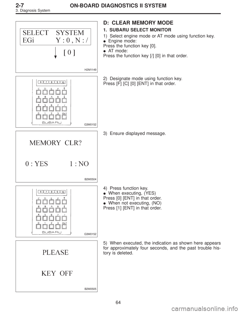
D: CLEAR MEMORY MODE
1. SUBARU SELECT MONITOR
1) Select engine mode or AT mode using function key.
�Engine mode:
Press the function key [0].
�AT mode:
Press the function key [/] [0] in that order.
G3M0152
2) Designate mode using function key.
Press [F] [C] [0] [ENT] in that order.
B2M0504
3) Ensure displayed message.
G3M0152
4) Press function key.
�When executing, (YES)
Press [0] [ENT] in that order.
�When not executing, (NO)
Press [1] [ENT] in that order.
B2M0505
5) When executed, the indication as shown here appears
for approximately four seconds, and the past trouble his-
tory is deleted.
64
2-7ON-BOARD DIAGNOSTICS II SYSTEM
3. Diagnosis System
Page 1919 of 3342
 Connect ST to Subaru select monitor cable.
ST 498357200 ADAPTER CABLE
OBD0006F
B2M0433D
(2) Open the cov")
OBD0669A
�Using data link connector for Subaru select monitor and
OBD-II general scan tool:
(1) Connect ST to Subaru select monitor cable.
ST 498357200 ADAPTER CABLE
OBD0006F
B2M0433D
(2) Open the cover and connect Subaru select monitor
to data link connector located in the lower portion of the
instrument panel (on the driver’s side), to the lower
cover.
CAUTION:
Do not connect scan tools except for Subaru select
monitor and OBD-II general scan tool.
OBD0060
6) Turn ignition switch to ON (engine OFF) and Subaru
select monitor switch to ON.
7) Start the engine.
NOTE:
�Ensure the selector lever is placed in the“P”position
before starting. (AT vehicles)
�Depress clutch pedal when starting the engine. (MT
vehicles)
8) Using the selector lever or shift lever, turn the“P”posi-
tion switch and the“N”position switch to ON.
9) Depress the brake pedal to turn the brake switch ON.
(AT vehicles)
10) Keep engine speed in the 2,500—3,000 rpm range
for 40 seconds.
NOTE:
On models without tachometer, use the Subaru select
monitor or tachometer (Secondary pickup type).
11) Place the selector lever or shift lever in the“D”posi-
tion (AT vehicles) or“1st”gear (MT vehicles) and drive the
vehicle at 5 to 10 km/h (3 to 6 MPH).
68
2-7ON-BOARD DIAGNOSTICS II SYSTEM
3. Diagnosis System
Page 1921 of 3342
 Start the engine.
NOTE:
�Ensure the selector lever is placed in the“P”position
before starting. (AT vehicles)
�Depress clutch pedal when starting the engine. (MT
vehicles)
4) Using the selector")
3) Start the engine.
NOTE:
�Ensure the selector lever is placed in the“P”position
before starting. (AT vehicles)
�Depress clutch pedal when starting the engine. (MT
vehicles)
4) Using the selector lever or shift lever, turn the“P”posi-
tion switch and the“N”position switch to ON.
5) Depress the brake pedal to turn the brake switch ON.
(AT vehicles)
6) Keep engine speed in the 2,500—3,000 rpm range for
40 seconds.
NOTE:
On models without tachometer, use the Subaru select
monitor or tachometer (Secondary pickup type).
7) Place the selector lever or shift lever in the“D”position
(AT vehicles) or“1st”gear (MT vehicles) and drive the
vehicle at 5 to 10 km/h (3 to 6 MPH).
NOTE:
�On AWD vehicles, release the parking brake.
�The speed difference between front and rear wheels
may light either the ABS or the ABS/TCS warning light, but
this indicates no malfunctions. When engine control diag-
nosis is finished, perform the ABS or the ABS/TCS memory
clearance procedure of self-diagnosis system.
4-4b [T6D2] or [T9K0], or 4-4c [T6D2] or [T9J0], or 4-4d
[T6D2] or [T9J0].>
8) Using the OBD-II general scan tool, check for diagnos-
tic trouble code(s) and record the result(s).
NOTE:
�For detailed operation procedures, refer to the OBD-II
General Scan Tool Instruction Manual.
�For details concerning diagnostic trouble codes, refer to
the DIAGNOSTIC TROUBLE CODE (DTC) LIST.
2-7 [T10A0], [T11A0].>
H2M1149
4. READ DIAGNOSTIC TROUBLE CODE (DTC)
SHOWN ON DISPLAY. (MODE FB0
MODE>)
Using Subaru select monitor, check for diagnostic trouble
code(s) and record the result(s).
1) Select engine mode using function key.
Press the function key [0].
70
2-7ON-BOARD DIAGNOSTICS II SYSTEM
3. Diagnosis System
Page 1928 of 3342
 Use engine grounding terminal or engine proper as the
grounding point to the body when measuring voltage and
resistance in the engine compartment.
OBD0040B
8) Use TCM mounting stud bolts a")
B2M0648A
7) Use engine grounding terminal or engine proper as the
grounding point to the body when measuring voltage and
resistance in the engine compartment.
OBD0040B
8) Use TCM mounting stud bolts at the body head ground-
ing point when measuring voltage and resistance inside the
passenger compartment.
9) Every MFI-related part is a precision part. Do not drop
them.
10) Observe the following cautions when installing a radio
in MFI equipped models.
CAUTION:
�The antenna must be kept as far apart as possible
from the control unit.
(The ECM is located under the steering column, inside
of the instrument panel lower trim panel.)
�The antenna feeder must be placed as far apart as
possible from the ECM and MFI harness.
�Carefully adjust the antenna for correct matching.
�When mounting a large power type radio, pay spe-
cial attention to the three items above mentioned.
�Incorrect installation of the radio may affect the
operation of the ECM.
11) Before disconnecting the fuel hose, disconnect the fuel
pump connector and crank the engine for more than five
seconds to release pressure in the fuel system. If engine
starts during this operation, run it until it stops.
12) Problems in the electronic-controlled automatic trans-
mission may be caused by failure of the engine, the elec-
tronic control system, the transmission proper, or by a com-
bination of these. These three causes must be distin-
guished clearly when performing diagnostics.
13) Diagnostics should be conducted by rotating with
simple, easy operations and proceeding to complicated,
difficult operations. The most important thing in diagnostics
is to understand the customer’s complaint, and distinguish
between the three causes.
77
2-7ON-BOARD DIAGNOSTICS II SYSTEM
4. Cautions
Page 1960 of 3342
 Measure resistance between spark plug cord contact
portions to check secondary coil.
: Terminals
#1—#2:
�2200 cc model
Is the resistance between 10 and 15 kΩ?
�2500 cc model
I")
B2M1050A
OBD0125B
2) Measure resistance between spark plug cord contact
portions to check secondary coil.
: Terminals
#1—#2:
�2200 cc model
Is the resistance between 10 and 15 kΩ?
�2500 cc model
Is the resistance between 18 and 24 kΩ?
: Go to next.
: Replace ignition coil.
: Terminals
#3—#4:
�2200 cc model
Is the resistance between 10 and 15 kΩ?
�2500 cc model
Is the resistance between 18 and 24 kΩ?
: Go to step8D4.
: Replace ignition coil.
OBD0126A
8D4CHECK HARNESS BETWEEN IGNITOR
AND IGNITION COIL CONNECTOR.
1) Turn ignition switch to OFF.
2) Disconnect connector from ignitor.
3) Measure resistance of harness connector between igni-
tion coil and ignitor.
: Connector & terminal
(B13) No. 5—(E12) No. 1:
Is the resistance less than 1Ω?
: Go to next.
: Go to next.
: Connector & terminal
(B13) No. 6—(E12) No. 3:
Is the resistance less than 1Ω?
: Go to step8D5.
: Go to next.
: Is there poor contact in coupling connector
(B22)?
: Repair poor contact in coupling connector.
: Repair open circuit in harness between ignition
coil and ignitor connector.
109
2-7ON-BOARD DIAGNOSTICS II SYSTEM
8. Diagnostics for Engine Starting Failure
Page 1964 of 3342

8E1CHECK OPERATING SOUND OF FUEL
PUMP.
Make sure that fuel pump is in operation for two seconds
when turning ignition switch to ON.
: Does fuel pump produce operating sound?
NOTE:
Fuel pump operation check can also be executed using
Subaru Select Monitor (Function mode: FD01).
For the procedure, refer to“COMPULSORY VALVE
OPERATION CHECK MODE”.
: Check fuel injector circuit.
: Go to step8E2.
OBD0132A
8E2CHECK GROUND CIRCUIT OF FUEL
PUMP.
1) Turn ignition switch to OFF.
2) Disconnect connector from fuel pump.
3) Measure resistance of harness connector between fuel
pump and chassis ground.
: Connector & terminal
(R58) No. 4—Chassis ground:
Is the resistance less than 5Ω?
: Go to step8E3.
: Repair open circuit in fuel pump ground circuit.
OBD0133A
8E3
CHECK POWER SUPPLY TO FUEL PUMP.
1) Turn ignition switch to ON.
2) Measure voltage of power supply circuit between fuel
pump connector and chassis ground.
: Connector & terminal
(R58) No. 1 (+)—Chassis ground (�):
Is the voltage more than 10 V?
: Replace fuel pump.
: Go to step8E4.
11 3
2-7ON-BOARD DIAGNOSTICS II SYSTEM
8. Diagnostics for Engine Starting Failure
Page 1968 of 3342

8F1CHECK OPERATING SOUND OF FUEL
PUMP.
Make sure that fuel pump is in operation for two seconds
when turning ignition switch to ON.
: Does fuel pump produce operating sound?
NOTE:
Fuel pump operation check can also be executed using
Subaru Select Monitor (Function mode: FD01).
For the procedure, refer to“COMPULSORY VALVE
OPERATION CHECK MODE”.
: Check fuel injector circuit.
: Go to step8F2.
OBD0132A
8F2CHECK GROUND CIRCUIT OF FUEL
PUMP.
1) Turn ignition switch to OFF.
2) Disconnect connector from fuel pump.
3) Measure resistance of harness connector between fuel
pump and chassis ground.
: Connector & terminal
(R58) No. 4—Chassis ground:
Is the resistance less than 5Ω?
: Go to step8F3.
: Repair open circuit in fuel pump ground circuit.
OBD0133A
8F3
CHECK POWER SUPPLY TO FUEL PUMP.
1) Turn ignition switch to ON.
2) Measure voltage of power supply circuit between fuel
pump connector and chassis ground.
: Connector & terminal
(R58) No. 1 (+)—Chassis ground (�):
Is the voltage more than 10 V?
: Replace fuel pump.
: Go to step8F4.
11 7
2-7ON-BOARD DIAGNOSTICS II SYSTEM
8. Diagnostics for Engine Starting Failure
Page 1985 of 3342
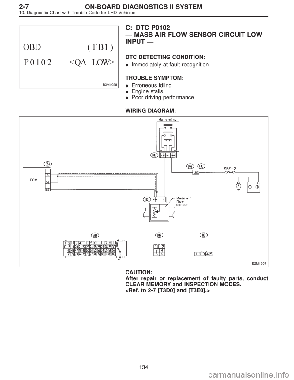
B2M1058
C: DTC P0102
—MASS AIR FLOW SENSOR CIRCUIT LOW
INPUT—
DTC DETECTING CONDITION:
�Immediately at fault recognition
TROUBLE SYMPTOM:
�Erroneous idling
�Engine stalls.
�Poor driving performance
WIRING DIAGRAM:
B2M1057
CAUTION:
After repair or replacement of faulty parts, conduct
CLEAR MEMORY and INSPECTION MODES.
134
2-7ON-BOARD DIAGNOSTICS II SYSTEM
10. Diagnostic Chart with Trouble Code for LHD Vehicles