Page 2298 of 3342
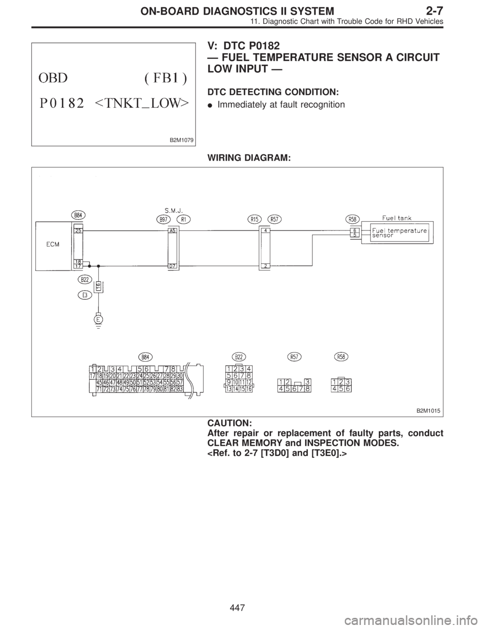
B2M1079
V: DTC P0182
—FUEL TEMPERATURE SENSOR A CIRCUIT
LOW INPUT—
DTC DETECTING CONDITION:
�Immediately at fault recognition
WIRING DIAGRAM:
B2M1015
CAUTION:
After repair or replacement of faulty parts, conduct
CLEAR MEMORY and INSPECTION MODES.
447
2-7ON-BOARD DIAGNOSTICS II SYSTEM
11. Diagnostic Chart with Trouble Code for RHD Vehicles
Page 2301 of 3342
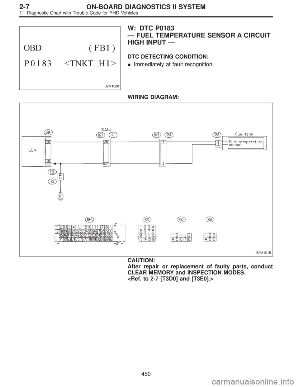
B2M1080
W: DTC P0183
—FUEL TEMPERATURE SENSOR A CIRCUIT
HIGH INPUT—
DTC DETECTING CONDITION:
�Immediately at fault recognition
WIRING DIAGRAM:
B2M1015
CAUTION:
After repair or replacement of faulty parts, conduct
CLEAR MEMORY and INSPECTION MODES.
450
2-7ON-BOARD DIAGNOSTICS II SYSTEM
11. Diagnostic Chart with Trouble Code for RHD Vehicles
Page 2325 of 3342
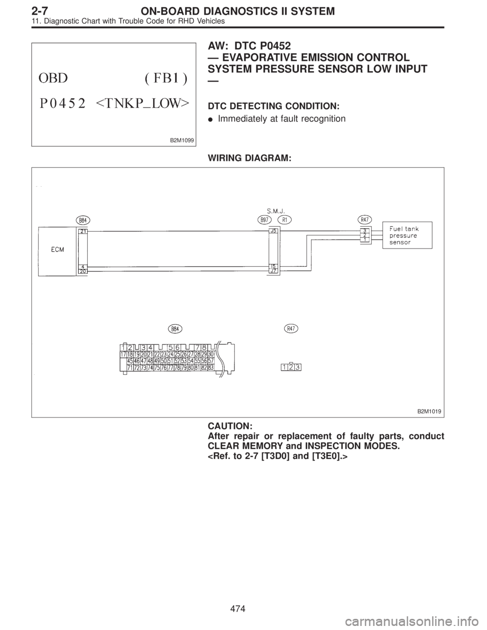
B2M1099
AW: DTC P0452
—EVAPORATIVE EMISSION CONTROL
SYSTEM PRESSURE SENSOR LOW INPUT
—
DTC DETECTING CONDITION:
�Immediately at fault recognition
WIRING DIAGRAM:
B2M1019
CAUTION:
After repair or replacement of faulty parts, conduct
CLEAR MEMORY and INSPECTION MODES.
474
2-7ON-BOARD DIAGNOSTICS II SYSTEM
11. Diagnostic Chart with Trouble Code for RHD Vehicles
Page 2330 of 3342
B2M1100
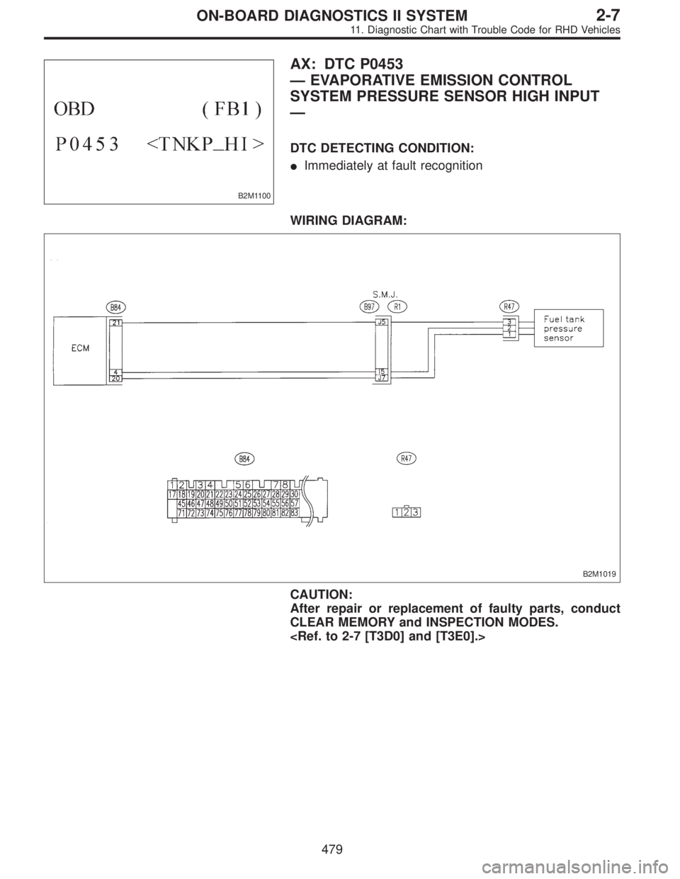
AX: DTC P0453
—EVAPORATIVE EMISSION CONTROL
SYSTEM PRESSURE SENSOR HIGH INPUT
—
DTC DETECTING CONDITION:
�Immediately at fault recognition
WIRING DIAGRAM:
B2M1019
CAUTION:
After repair or replacement of faulty parts, conduct
CLEAR MEMORY and INSPECTION MODES.
479
2-7ON-BOARD DIAGNOSTICS II SYSTEM
11. Diagnostic Chart with Trouble Code for RHD Vehicles
Page 2479 of 3342
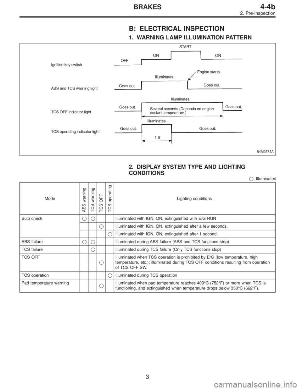
B: ELECTRICAL INSPECTION
1. WARNING LAMP ILLUMINATION PATTERN
B4M0372A
2. DISPLAY SYSTEM TYPE AND LIGHTING
CONDITIONS
�: Illuminated
Mode
ABS warning
TCS warning
TCS OFF
TCS operating
Lighting conditions
Bulb check��Illuminated with IGN. ON, extinguished with E/G RUN
�Illuminated with IGN. ON, extinguished after a few seconds.
�Illuminated with IGN. ON, extinguished after 1 second.
ABS failure��Illuminated during ABS failure (ABS and TCS functions stop)
TCS failure�Illuminated during TCS failure (Only TCS functions stop)
TCS OFF
�Illuminated when TCS operation is prohibited by E/G (low temperature, high
temperature, etc.); illuminated during TCS OFF conditions resulting from operation
of TCS OFF SW.
TCS operation�Illuminated during TCS operation
Pad temperature warning
�Illuminated when pad temperature reaches 400°C (752°F) or more when TCS is
functioning, and extinguished when temperature drops below 350°C (662°F).
3
4-4bBRAKES
2. Pre-inspection
Page 2486 of 3342

3. LIST OF ABS/TCS ON-BOARD DIAGNOSTICS
FUNCTIONS
Trouble codeDiagnostic items
Detection timingIndicator
light ON
Parts concerned
At initial checking
Under no control
Under ABS control
Under TCS control
In diagnostic mode
ABS warning light
TCS warning light
TCS OFF indicator light
21 FR
23 FL
25 RR
27 RLDetection of fault in ABS sensor hardware
���� ��—ABS sensor (ABS/TCS C/M)
22 FR
24 FL
26 RR
28 RLDetection of fault in ABS sensor software
��� ��—ABS sensor (ABS/TCS C/M)
��� ��—ABS sensor harness circuit (ABS/TCS C/M)
Detection of fault in ABS sensor software
���—ABS sensor and solenoid valve (ABS/TCS C/M)
���—ABS sensor (ABS/TCS C/M)
Detection of fault in sensor software
���� ��—ABS sensor (ABS/TCS C/M)
31 FRI
32 FRO
33 FLI
34 FLO
35 RRI
36 RRO
37 RLI
38 RLO
61 TCS1
62 TCS2Abnormal valve
����*
���—Solenoid valve (ABS/TCS C/M)
41 Abnormal ABS/TCS C/M
���� ��—ABS/TCS C/M
42 Abnormal line voltage
�������—Power source operating environment (ABS/TCS C/M)
—Power source voltage drop
���� ��—
������—
*: Except when trouble code is being displayed.
10
4-4bBRAKES
5. Control Module I/O Signal
Page 2489 of 3342
6. Diagnostics Chart for On-board
Diagnosis System
A: BASIC DIAGNOSTICS PROCEDURE
TROUBLE OCCURS.
Ask the customer when and how the
trouble occurred using interview
check list.
PRE-INSPECTION
INSPECTION MODE
CALLING UP A TROUBLE CODE.
�No trouble code is readable.
�
Inspection using Diagnostic Chart for
Warning Light Failure.
Record all trouble codes.
Trouble codes
are issued.
�Only the start code is issued.
Inspection using General Diagnostics
Chart
Perform diagnostics in accordance with trouble code.
Trouble code
designated.
�
Repair.�
Clear memory.
INSPECTION MODE
CALLING UP A TROUBLE CODE.
Only the start code is issued.
CONFIRMATION TEST
END
NOTE:
�To check harness for broken wires or short circuits,
shake it while holding it or the connector.
�When TCS warning light illuminates, read and record
trouble code indicated by TCS warning light.
�
�
�
�
�
�
�
�
�
�
�
�
13
4-4bBRAKES
6. Diagnostics Chart for On-board Diagnosis System
Page 2568 of 3342
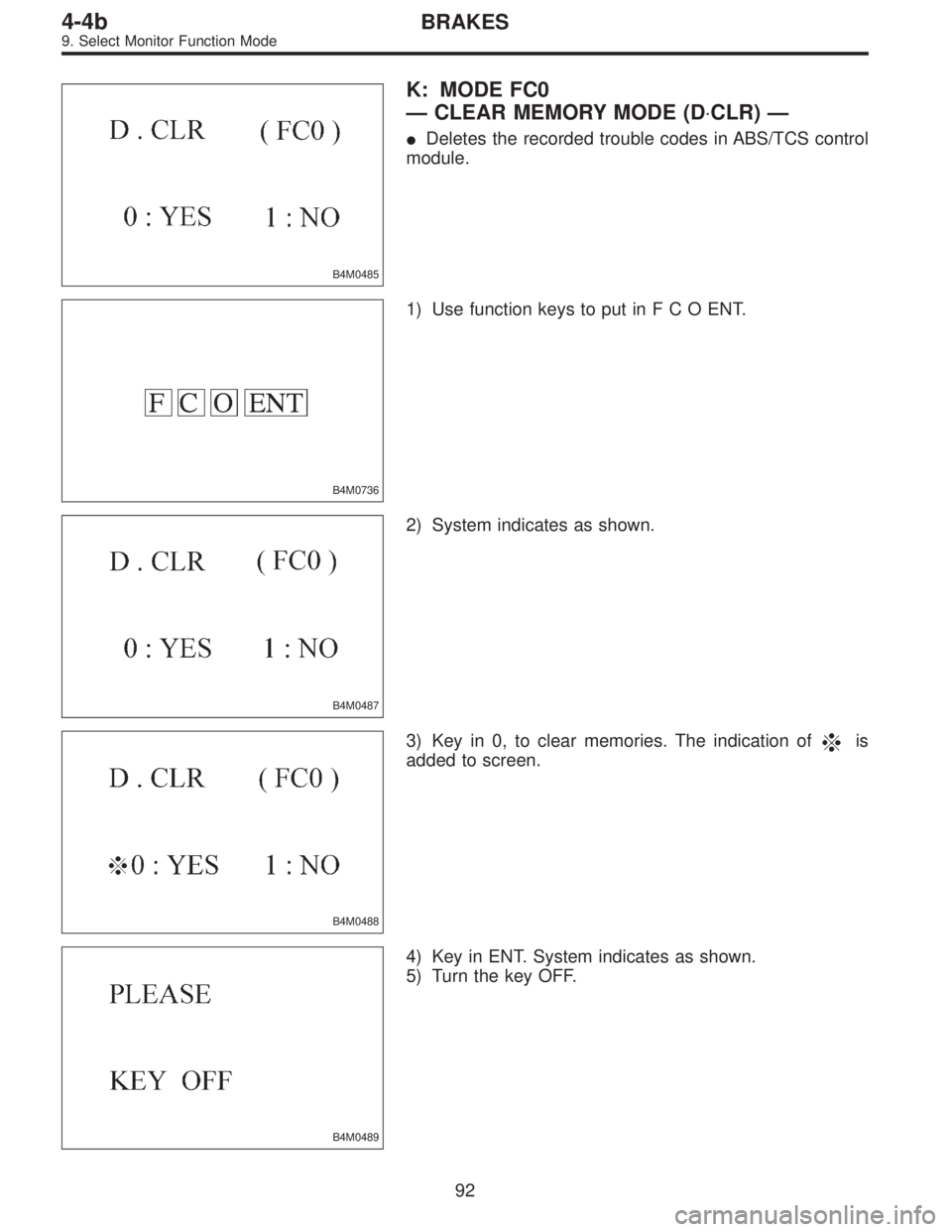
B4M0485
K: MODE FC0
—CLEAR MEMORY MODE (D⋅CLR)—
�Deletes the recorded trouble codes in ABS/TCS control
module.
B4M0736
1) Use function keys to put inFCOENT.
B4M0487
2) System indicates as shown.
B4M0488
3) Key in 0, to clear memories. The indication ofis
added to screen.
B4M0489
4) Key in ENT. System indicates as shown.
5) Turn the key OFF.
92
4-4bBRAKES
9. Select Monitor Function Mode
![SUBARU LEGACY 1997 Service Repair Manual 6. Diagnostics Chart for On-board
Diagnosis System
A: BASIC DIAGNOSTICS PROCEDURE
TROUBLE OCCURS.
Ask the customer when and how the
trouble occurred using interview
check list. <Ref. to 4-4b [T6B0].>](/manual-img/17/57434/w960_57434-2488.png "SUBARU LEGACY 1997 Service Repair Manual 6. Diagnostics Chart for On-board
Diagnosis System
A: BASIC DIAGNOSTICS PROCEDURE
TROUBLE OCCURS.
Ask the customer when and how the
trouble occurred using interview
check list. <Ref. to 4-4b [T6B0].>")