Page 2569 of 3342
10. Diagnostic Chart with Select
Monitor
A: BASIC DIAGNOSTIC CHART
TROUBLE OCCURS.
Ask the customer when and how
the trouble occurred using
interview check list.
PRE-INSPECTION
INSPECTION MODE
Use select monitor, retrieve
trouble code in function modes
FB0, FB1 and record the code.Only the start code is
designated.
�
Inspection using General
Diagnostics Chart
Trouble code designated.
Perform diagnostics in accordance with trouble code.
Trouble code
designated.
�
Repair.�
Clear memory.
INSPECTION MODE
Use select monitor, retrieve trouble code in function
modes FB0, FB1 and record the code.
No trouble code designated.
CONFIRMATION TEST
END
NOTE:
To check harness for broken wires or short circuits, shake
it while holding it or the connector.
�
�
�
�
�
�
�
�
�
�
�
93
4-4bBRAKES
10. Diagnostic Chart with Select Monitor
Page 2571 of 3342
CodeDisplay screen
(FB0)Diagnostic items (select monitor FB1) Display screen (FB1)Ref. to
4-4b
Abnormal stroke sen-
sor and stop light
switch54 PSS & BLSOpen/short")
Diagnostic items
(select monitor FB0)CodeDisplay screen
(FB0)Diagnostic items (select monitor FB1) Display screen (FB1)Ref. to
4-4b
Abnormal stroke sen-
sor and stop light
switch54 PSS & BLSOpen/short circuits of stroke sensor B.SW HARD [T10Y1]
Comparison of stroke sensor and acceleration B.SW SOFT(G) [T10Y2]
Comparison of stroke sensor and stop light switch B.SW SOFT(B) [T10Y3]
Comparison of stroke sensor and pump B.SW SOFT(P) [T10Y4]
Open circuit of stop light switch B.SW SOFT(O) [T10Y5]
Abnormal fluid level
sensor line57 FLUID LEVEL SS Abnormal fluid level sensor line FLUID LEVEL SS [T10Z0]
Abnormal pressure
switch58 PRESSURE SW Abnormal pressure switch PRESSURE SW [T10AA0]
Abnormal TCS1 valve 61 TCS1 VALVE Abnormal TCS1 valve TCS1 VALVE [T10AB0]
Abnormal TCS2 valve 62 TCS2 VALVE Abnormal TCS2 valve TCS2 VALVE [T10AC0]
1. IF THE SELECT MONITOR IS USED FOR
TROUBLESHOOTING, IT IS ADVISED TO FOLLOW
THE PROCEDURE BELOW
1) Activate function FB0 to read the most recent trouble
code and record it.
2) Activate function FB1 to read all trouble codes and
record them.
(If troubles occur in the wheel speed sensor, stop & brake
switch, valve relay or motor system, detailed data on
troubles are displayed by the FB1 function, allowing you to
easily locate points where need repair.)
3) Perform troubleshooting mainly in the FB1 mode.
95
4-4bBRAKES
10. Diagnostic Chart with Select Monitor
Page 2575 of 3342
B4M0494
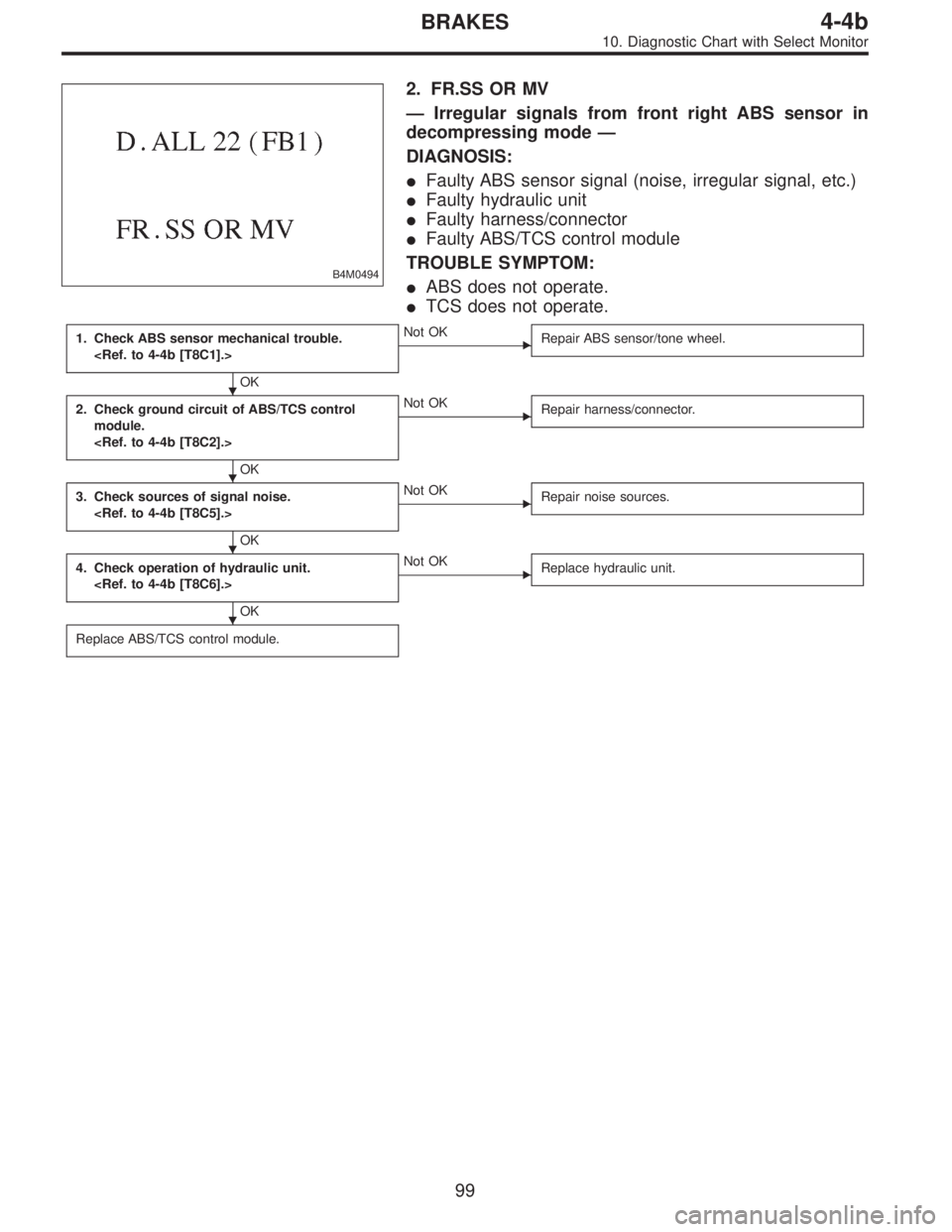
2. FR.SS OR MV
—Irregular signals from front right ABS sensor in
decompressing mode—
DIAGNOSIS:
�Faulty ABS sensor signal (noise, irregular signal, etc.)
�Faulty hydraulic unit
�Faulty harness/connector
�Faulty ABS/TCS control module
TROUBLE SYMPTOM:
�ABS does not operate.
�TCS does not operate.
1. Check ABS sensor mechanical trouble.
OK
�Not OK
Repair ABS sensor/tone wheel.
2. Check ground circuit of ABS/TCS control
module.
OK
�Not OK
Repair harness/connector.
3. Check sources of signal noise.
OK
�Not OK
Repair noise sources.
4. Check operation of hydraulic unit.
OK
�Not OK
Replace hydraulic unit.
Replace ABS/TCS control module.
�
�
�
�
99
4-4bBRAKES
10. Diagnostic Chart with Select Monitor
Page 2578 of 3342

�Faulty harness/connector
�Faulty AB")
B4M0498
G: TROUBLE CODE 24
1. FL.SS W.SPEED
—Irregular signals from front left ABS sensor—
DIAGNOSIS:
�Faulty ABS sensor signal (noise, irregular signal, etc.)
�Faulty harness/connector
�Faulty ABS/TCS control module
TROUBLE SYMPTOM:
�ABS and TCS do not operate.
NOTE:
The procedures used are the same as those for FR.SS
W.SPEED.
B4M0499
2. FL.SS OR MV
—Irregular signals from front left ABS sensor in
decompressing mode—
DIAGNOSIS:
�Faulty ABS sensor signal (noise, irregular signal, etc.)
�Faulty hydraulic unit
�Faulty harness/connector
�Faulty ABS/TCS control module
TROUBLE SYMPTOM:
�ABS and TCS do not operate.
NOTE:
The procedures used are the same as those for FR.SS OR
MV.
B4M0500
3. FL.SS OVER
—Excessive speed of front left ABS sensor signal—
DIAGNOSIS:
�Faulty ABS sensor signal (noise, irregular signal, etc.)
�Faulty harness/connector
�Faulty ABS/TCS control module
TROUBLE SYMPTOM:
�ABS and TCS do not operate.
NOTE:
The procedures used are the same as those for FR.SS
OVER.
102
4-4bBRAKES
10. Diagnostic Chart with Select Monitor
Page 2580 of 3342

�Faulty harness/connector
�Faulty AB")
B4M0503
I: TROUBLE CODE 26
1. RR.SS W.SPEED
—Irregular signals from rear right ABS sensor—
DIAGNOSIS:
�Faulty ABS sensor signal (noise, irregular signal, etc.)
�Faulty harness/connector
�Faulty ABS/TCS control module
TROUBLE SYMPTOM:
�ABS and TCS do not operate.
NOTE:
The procedures used are the same as those for FR.SS
W.SPEED.
B4M0504
2. RR.SS OR MV
—Irregular signals from rear right ABS sensor in
decompressing mode—
DIAGNOSIS:
�Faulty ABS sensor signal (noise, irregular signal, etc.)
�Faulty hydraulic unit
�Faulty harness/connector
�Faulty ABS/TCS control module
TROUBLE SYMPTOM:
�ABS and TCS do not operate.
NOTE:
The procedures used are the same as those for FR.SS OR
MV.
B4M0505
3. RR.SS OVER
—Excessive speed of rear right ABS sensor signal—
DIAGNOSIS:
�Faulty ABS sensor signal (noise, irregular signal, etc.)
�Faulty harness/connector
�Faulty ABS/TCS control module
TROUBLE SYMPTOM:
�ABS and TCS do not operate.
NOTE:
The procedures used are the same as those for FR.SS
OVER.
104
4-4bBRAKES
10. Diagnostic Chart with Select Monitor
Page 2582 of 3342

�Faulty harness/connector
�Faulty ABS")
B4M0508
K: TROUBLE CODE 28
1. RL.SS W.SPEED
—Irregular signals from rear left ABS sensor—
DIAGNOSIS:
�Faulty ABS sensor signal (noise, irregular signal, etc.)
�Faulty harness/connector
�Faulty ABS/TCS control module
TROUBLE SYMPTOM:
�ABS and TCS do not operate.
NOTE:
The procedures used are the same as those for FR.SS
W.SPEED.
B4M0509
2. RL.SS OR MV
—Irregular signals from rear left ABS sensor in
decompressing mode—
DIAGNOSIS:
�Faulty ABS sensor signal (noise, irregular signal, etc.)
�Faulty hydraulic unit
�Faulty harness/connector
�Faulty ABS/TCS control module
TROUBLE SYMPTOM:
�ABS and TCS do not operate.
NOTE:
The procedures used are the same as those for FR.SS OR
MV.
B4M0510
3. RL.SS OVER
—Excessive speed of rear left ABS sensor signal—
DIAGNOSIS:
�Faulty ABS sensor signal (noise, irregular signal, etc.)
�Faulty harness/connector
�Faulty ABS/TCS control module
TROUBLE SYMPTOM:
�ABS and TCS do not operate.
NOTE:
The procedures used are the same as those for FR.SS
OVER.
106
4-4bBRAKES
10. Diagnostic Chart with Select Monitor
Page 2604 of 3342
 and,
when it operates, acceleration can become slow*. T")
12. Phenomena Peculiar to the System
1. WHEN TRAVELING WITH EXTREMELY UNDER
INFLATED TIRES
The TCS is apt to operate (particularly when turning) and,
when it operates, acceleration can become slow*. This
state is not abnormal. Immediately restore the tires to nor-
mal by traveling after releasing the TCS with the TCS OFF
switch.
* Poor acceleration is sometimes caused by the engine
itself. Check whether or not the TCS operating indicator
light (green) comes on to determine that the failure is
caused by the TCS control.
2. WHEN THE T TIRES ARE FITTED
The TCS is apt to operate (particularly when turning) and,
when it operates, acceleration can become slow. This state
is not abnormal. Immediately restore the tires to normal by
traveling after releasing the TCS with the TCS OFF switch.
3. WHEN OPERATING THE TCS CONTINUOUSLY ON
A SLOPE IMPOSSIBLE TO CLIMB OR IN STACK
S TAT E
When operating the TCS for a long time, it can be auto-
matically turned off (the OFF indicator light will come on),
stopping braking. This state is not abnormal. It automati-
cally resets by stopping and leaving the vehicle.
4. WHEN HEAVY LOAD IS PLACED ON THE BRAKES
If service brakes are used too often when descending a
long slope, heavy load can be placed on the brakes. To
prevent this problem, the TCS is automatically turned off
(the OFF indicator light will come on). This state is not
abnormal. Stop the vehicle and leave it in the same way as
step 3, it automatically resets.
5. KICKBACK TO THE BRAKE PEDAL WHEN THE
ABS IS OPERATING
Compared with ABS of the AWD model system, pedal kick-
back with large amplitude of vibration and long cycle can
be felt. This is caused by the difference in system configu-
ration and, therefore, not abnormal. If you receive an
inquiry from your clients, fully explain this point.
128
4-4bBRAKES
12. Phenomena Peculiar to the System
Page 2613 of 3342
Front left wheel 49—19
0.12—1V
(When it is 20 Hz.) Front right wheel 14—15
Rear le")
Contents Terminal No.Input/Output signal
Measured value and measuring conditions
ABS sensor
(Wheel
speed
sensor)Front left wheel 49—19
0.12—1V
(When it is 20 Hz.) Front right wheel 14—15
Rear left wheel 16—17
Rear right wheel 18—46
Hydraulic
control unitSolenoid
valveFront left outlet 51—1
10—13 V when the valve is OFF and
less than 1.5 V when the valve is ON. Front right outlet 3—1
Rear left outlet 4—1
Rear right outlet 50—1
Front left inlet 24—1
Front right inlet 30—1
Rear left inlet 31—1
Rear right inlet 23—1
Relay boxValve relay power supply 27—110—13 V when ignition switch is ON.
Valve relay coil 47—1 Less than 1.5 V when ignition switch is ON.
Motor relay coil 22—1More than 10 V when the ABS control does not operate still
and less than 1.5 V when ABS operates.
Motor monitoring 10—1Less than 1.5 V when the ABS control does not operate still
and more than 10 V when ABS operates.
G sensor
(AWD
model only)power supply 8—45 4.75—5.25 V
ground 45—
output 7—45 2.3±0.2 V when vehicle is in horizontal position.
Stop light switch 36—1Less than 1.5 V when the stop light is OFF and more than
4.5 V when the stop light is ON.
ABS warning light 54—1Less than 1.5 V during 1.5 seconds when ignition switch is
ON, and 10—14 V after 1.5 seconds.
AT ABS signal
(AT model only)12—1Less than 1.5 V when the ABS control does not operate still
and more than 5.5 V when ABS operates.
ABS operation signal monitor 39—1Less than 1.5 V when the ABS control does not operate still
and more than 5.5 V when ABS operates.
Select
monitorData is received. 11—1 Less than 1.5 V when no data is received.
Data is sent. 38—1 4.75—5.25 V when no data is sent.
Diagnosis
connectorTerminal No. 3 5—110—14 V when ignition switch is ON.
Terminal No. 6 13—110—14 V when ignition switch is ON.
Power supply 28—110—14 V when ignition switch is ON.
Grounding line 1—
Grounding line 55—
8
4-4cBRAKES [ABS 5.3 TYPE]
5. Control Module I/O Signal
![SUBARU LEGACY 1997 Service Repair Manual 10. Diagnostic Chart with Select
Monitor
A: BASIC DIAGNOSTIC CHART
TROUBLE OCCURS.
Ask the customer when and how
the trouble occurred using
interview check list.
<Ref. to 4-4b [T6B0].>
PRE-INSPECTION](/manual-img/17/57434/w960_57434-2568.png "SUBARU LEGACY 1997 Service Repair Manual 10. Diagnostic Chart with Select
Monitor
A: BASIC DIAGNOSTIC CHART
TROUBLE OCCURS.
Ask the customer when and how
the trouble occurred using
interview check list.
<Ref. to 4-4b [T6B0].>
PRE-INSPECTION")