Page 120 of 3342
![SUBARU LEGACY 1997 Service Repair Manual
4-4d
[T1
0A01
BRAKES
[ABS
5
.3i
TYPE]
10
.
Diagnostics
Chart
with
Select
Monitor
10
.
Diagnostics
Chart
with
Select
Monitor
I
TROUBLE
OCCURS
.I
A
:
BASIC
DIAGNOSTIC
CHART
Is
Select
Monitor
avai](/manual-img/17/57434/w960_57434-119.png "SUBARU LEGACY 1997 Service Repair Manual
4-4d
[T1
0A01
BRAKES
[ABS
5
.3i
TYPE]
10
.
Diagnostics
Chart
with
Select
Monitor
10
.
Diagnostics
Chart
with
Select
Monitor
I
TROUBLE
OCCURS
.I
A
:
BASIC
DIAGNOSTIC
CHART
Is
Select
Monitor
avai")
4-4d
[T1
0A01
BRAKES
[ABS
5
.3i
TYPE]
10
.
Diagnostics
Chart
with
Select
Monitor
10
.
Diagnostics
Chart
with
Select
Monitor
I
TROUBLE
OCCURS
.I
A
:
BASIC
DIAGNOSTIC
CHART
Is
Select
Monitor
available?
No
Yes
Ask
the
customer
when
and
how
the
trouble
occurred
using
interview
check
list
.
I
PRE-INSPECTION
I
Use
select
monitor,
retrieve
trouble
code
in
function
mode
FBiand
record
the
code
.
Perform
diagnostics
in
accordance
with
trouble
code
.
No
corresponding
trouble
code
Diagnostics
Chart
for
On-board
Diagnosis
System
Inspection
using
General
Diagnostics
chart
Trouble
code
is
designated
or
ABS
warning
light
constantly
remains
on
.
Repair
.
Clear
memory
.
I
INSPECTION
MODE
I
Use
select
monitor,
retrieve
trouble
code
in
function
model
FB1and
recordthe
code
.
No
trouble
code
is
designated
and
ABS
warning
light
goes
out
after
turning
on
.
I
CONFIRMATION
TEST
I
END
B4M1076A
CAUTION
:
Remove
foreign
matter
(dust,
water,
etc
.)
from
the
ABSCM&H/U
connector
during
removal
and
installation
.
NOTE
:
To
check
harness
for
broken
wires
or
short
circuits,
shake
it
while
holding
it
or
the
connector
.
102
Page 246 of 3342

1. Foreword
This chapter describes major inspection and service pro-
cedures for the engine mounted on the body. For proce-
dures not found in this chapter, refer to the service proce-
dure section in the applicable chapter.
2. Ignition Timing
A: MEASUREMENT
1. 2200 cc MODEL
1) Warm-up the engine.
G2M0094
2) To check the ignition timing, connect a timing light to #1
cylinder spark plug cord, and illuminate the timing mark
with the timing light.
3) Start the engine at idle speed and check the ignition
timing.
If the timing is not correct, check the ignition control sys-
tem.
Ignition timing [BTDC/rpm]:
14°±8°/700 (MT)
20°±8°/700 (AT)
2. 2500 cc MODEL
CAUTION:
After warming-up, engine becomes very hot. Be care-
ful not to burn yourself during measurement.
1) Warm-up the engine.
B2M0750A
2) To check the ignition timing, connect a timing light to #1
cylinder spark plug cord, and illuminate the timing mark
with the timing light.
3) Start the engine at idle speed and check the ignition
timing.
If the timing is not correct, check the ignition control sys-
tem.
Ignition timing [BTDC/rpm]:
15°±8°/700
2
2-2
1. Foreword - 2. Ignition Timing
Page 247 of 3342

1. Foreword
This chapter describes major inspection and service pro-
cedures for the engine mounted on the body. For proce-
dures not found in this chapter, refer to the service proce-
dure section in the applicable chapter.
2. Ignition Timing
A: MEASUREMENT
1. 2200 cc MODEL
1) Warm-up the engine.
G2M0094
2) To check the ignition timing, connect a timing light to #1
cylinder spark plug cord, and illuminate the timing mark
with the timing light.
3) Start the engine at idle speed and check the ignition
timing.
If the timing is not correct, check the ignition control sys-
tem.
Ignition timing [BTDC/rpm]:
14°±8°/700 (MT)
20°±8°/700 (AT)
2. 2500 cc MODEL
CAUTION:
After warming-up, engine becomes very hot. Be care-
ful not to burn yourself during measurement.
1) Warm-up the engine.
B2M0750A
2) To check the ignition timing, connect a timing light to #1
cylinder spark plug cord, and illuminate the timing mark
with the timing light.
3) Start the engine at idle speed and check the ignition
timing.
If the timing is not correct, check the ignition control sys-
tem.
Ignition timing [BTDC/rpm]:
15°±8°/700
2
2-2
1. Foreword - 2. Ignition Timing
Page 248 of 3342
 Before checking idle speed, check the following:
(1) Ensure that air cleaner element is free from
clogging, ignition timing is correct, spark plugs are in
good c")
3. Engine Idle Speed
A: MEASUREMENT
1) Before checking idle speed, check the following:
(1) Ensure that air cleaner element is free from
clogging, ignition timing is correct, spark plugs are in
good condition, and that hoses are connected properly.
(2) Ensure that malfunction indicator light (CHECK
ENGINE light) does not illuminate.
2) Warm-up the engine.
G2M0096
3) Connect Subaru Select Monitor or the OBD-II general
scan tool to data link connector.
CAUTION:
When connecting Subaru Select Monitor, turn ignition
switch to OFF.
4) Start the engine and measure engine speed.
NOTE:
Engine speed is indicated on Subaru Select Monitor by
selecting “MODE F04”.
G2M0097
NOTE:
�When using the OBD-II general scan tool, carefully read
its operation manual.
�When Subaru Select Monitor is not used, attach the
pickup sensor on tachometer (Secondary pickup type) to
#1 cylinder spark plug cord.
�This ignition system provides simultaneous ignition for
#1 and #2 plugs. It must be noted that some tachometers
may register twice that of actual engine speed.
5) Check idle speed when unloaded. (With headlights,
heater fan, rear defroster, radiator fan, air conditioning, etc.
OFF)
Idle speed (No load and gears in neutral (MT) or N or
P (AT) position):
700±100 rpm
6) Check idle speed when loaded. (Turn air conditioning
switch to “ON” and operate compressor for at least one
minute before measurement.)
Idle speed [A/C“ON”, no load and gears in neutral
(MT) or N or P (AT) position]:
850±50 rpm
CAUTION:
Never rotate idle adjusting screw. If idle speed is out
of specifications, refer to General On-board Diagnosis
Table under “2-7 On-Board Diagnostics II System”.
3
2-2
3. Engine Idle Speed
Page 249 of 3342
 After warming-up the engine, turn ignition switch to
OFF.
2) Make sure that the battery is fully charged.
3) Remove all the spark plugs.
4) Dis")
4. Engine Compression
A: MEASUREMENT
1. 2200 cc MODEL
1) After warming-up the engine, turn ignition switch to
OFF.
2) Make sure that the battery is fully charged.
3) Remove all the spark plugs.
4) Disconnect connectors from fuel injectors.
5) Fully open throttle valve.
6) Check the starter motor for satisfactory performance
and operation.
G2M0098
7) Hold the compression gauge tight against the spark
plug hole.
CAUTION:
When using a screw-in type compression gauge, the
screw (put into cylinder head spark plug hole) should
be less than 18 mm (0.71 in) long.
8) Crank the engine by means of the starter motor, and
read the maximum value on the gauge when the pointer is
steady.
9) Perform at least two measurements per cylinder, and
make sure that the values are correct.
Compression (200—300 rpm and fully open throttle):
Standard
1,079—1,275 kPa
(11.0—13.0 kg/cm
2, 156—185 psi)
Limit
883 kPa (9.0 kg/cm
2, 128 psi)
Difference between cylinders
196 kPa (2.0 kg/cm
2, 28 psi)
2. 2500 cc MODEL
CAUTION:
After warming-up, engine becomes very hot. Be care-
ful not to burn yourself during measurement.
1) After warming-up the engine, turn ignition switch to
OFF.
2) Make sure that the battery is fully charged.
3) Remove all the spark plugs.
[W3E0].>
4) Disconnect connectors from fuel injectors.
4
2-2
4. Engine Compression
Page 260 of 3342
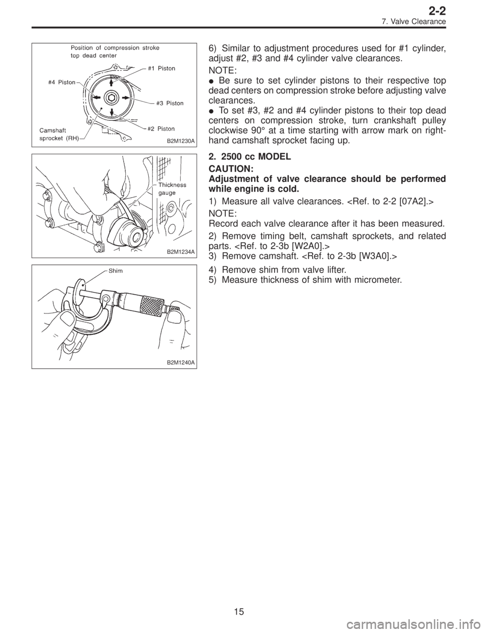
B2M1230A
6) Similar to adjustment procedures used for #1 cylinder,
adjust #2, #3 and #4 cylinder valve clearances.
NOTE:
�Be sure to set cylinder pistons to their respective top
dead centers on compression stroke before adjusting valve
clearances.
�To set #3, #2 and #4 cylinder pistons to their top dead
centers on compression stroke, turn crankshaft pulley
clockwise 90°at a time starting with arrow mark on right-
hand camshaft sprocket facing up.
B2M1234A
2. 2500 cc MODEL
CAUTION:
Adjustment of valve clearance should be performed
while engine is cold.
1) Measure all valve clearances.
NOTE:
Record each valve clearance after it has been measured.
2) Remove timing belt, camshaft sprockets, and related
parts.
3) Remove camshaft.
B2M1240A
4) Remove shim from valve lifter.
5) Measure thickness of shim with micrometer.
15
2-2
7. Valve Clearance
Page 567 of 3342
 Check the routing of clutch cable for smoothness.
2) Excessive tightnes")
1. General
A: PRECAUTION
When servicing clutch system, pay attention to the follow-
ing items.
1. MECHANICAL APPLICATION TYPE
1) Check the routing of clutch cable for smoothness.
2) Excessive tightness or looseness of clutch cable have
a bad influence upon the cable durability.
3) Apply grease sufficiently to the connecting portion of
clutch pedal.
4) Apply grease sufficiently to the release lever portion.
5) Position clutch cable through the center of toe board
hole and route it smoothly. Adjustment is done by moving
the outer cable.
6) Make sure not to let the clutch chatter when starting
forward or rearward. If clutch chattering occurs, readjust so
that the bend of clutch outer cable becomes flatter.
B2M1177A
2. HYDRAULIC APPLICATION TYPE
1) Check fluid level using a scale on outside of reservoir
tank. If the level is below“MIN”, add clutch fluid to bring it
up to“MAX”.
Recommended clutch fluid:
FMVSS No. 116, fresh DOT3 or DOT4 brake fluid
CAUTION:
�Avoid mixing different brakes of brake fluid to pre-
vent degradation of the fluid.
�Be careful not to allow dirt or dust to get into the
reservoir tank.
�Use fresh DOT3 or DOT4 brake fluid when refilling
fluid.
2) Make sure that clutch fluid does not leak from master
cylinder, operating cylinder and piping.
3) Apply grease sufficiently to the release lever pinion.
4) Check for proper clutch disengagement and clutch
pedal return ability.
G2M0234
2. On-Car Service
1. MECHANICAL APPLICATION TYPE
1) Remove release lever return spring from lever (Models
without hill holder only).
2) Adjust spherical nut so that the play is within the speci-
fied value at the lever end (center of spherical nut).
CAUTION:
Take care not to twist the cable during adjustment
Play: 3 — 4 mm (0.12 — 0.16 in)
Full stroke: 24 — 26 mm (0.94 — 1.02 in)
6
2-10SERVICE PROCEDURE
1. General - 2. On-Car Service
Page 568 of 3342
 Check the routing of clutch cable for smoothness.
2) Excessive tightnes")
1. General
A: PRECAUTION
When servicing clutch system, pay attention to the follow-
ing items.
1. MECHANICAL APPLICATION TYPE
1) Check the routing of clutch cable for smoothness.
2) Excessive tightness or looseness of clutch cable have
a bad influence upon the cable durability.
3) Apply grease sufficiently to the connecting portion of
clutch pedal.
4) Apply grease sufficiently to the release lever portion.
5) Position clutch cable through the center of toe board
hole and route it smoothly. Adjustment is done by moving
the outer cable.
6) Make sure not to let the clutch chatter when starting
forward or rearward. If clutch chattering occurs, readjust so
that the bend of clutch outer cable becomes flatter.
B2M1177A
2. HYDRAULIC APPLICATION TYPE
1) Check fluid level using a scale on outside of reservoir
tank. If the level is below“MIN”, add clutch fluid to bring it
up to“MAX”.
Recommended clutch fluid:
FMVSS No. 116, fresh DOT3 or DOT4 brake fluid
CAUTION:
�Avoid mixing different brakes of brake fluid to pre-
vent degradation of the fluid.
�Be careful not to allow dirt or dust to get into the
reservoir tank.
�Use fresh DOT3 or DOT4 brake fluid when refilling
fluid.
2) Make sure that clutch fluid does not leak from master
cylinder, operating cylinder and piping.
3) Apply grease sufficiently to the release lever pinion.
4) Check for proper clutch disengagement and clutch
pedal return ability.
G2M0234
2. On-Car Service
1. MECHANICAL APPLICATION TYPE
1) Remove release lever return spring from lever (Models
without hill holder only).
2) Adjust spherical nut so that the play is within the speci-
fied value at the lever end (center of spherical nut).
CAUTION:
Take care not to twist the cable during adjustment
Play: 3 — 4 mm (0.12 — 0.16 in)
Full stroke: 24 — 26 mm (0.94 — 1.02 in)
6
2-10SERVICE PROCEDURE
1. General - 2. On-Car Service