Page 151 of 3342
![SUBARU LEGACY 1997 Service Repair Manual
4-4d
[rionns1
BRAKES
[ABS
5
.31
TYPE]
10
.
Diagnostics
Chart
withSelect
Monitor
G4M0700
I
G4M0701
I
1
101111116
I
CHECK
INSTALLATION
OF
TONE
WHEEL
.
Tightening
torque
:
13
±
3
N~m
(1.3
f
0
.3
k](/manual-img/17/57434/w960_57434-150.png "SUBARU LEGACY 1997 Service Repair Manual
4-4d
[rionns1
BRAKES
[ABS
5
.31
TYPE]
10
.
Diagnostics
Chart
withSelect
Monitor
G4M0700
I
G4M0701
I
1
101111116
I
CHECK
INSTALLATION
OF
TONE
WHEEL
.
Tightening
torque
:
13
±
3
N~m
(1.3
f
0
.3
k")
4-4d
[rionns1
BRAKES
[ABS
5
.31
TYPE]
10
.
Diagnostics
Chart
withSelect
Monitor
G4M0700
I
G4M0701
I
1
101111116
I
CHECK
INSTALLATION
OF
TONE
WHEEL
.
Tightening
torque
:
13
±
3
N~m
(1.3
f
0
.3
kg-m,
9
±
2
.2
ft-Ib)
CHECK
:
Are
thetone
wheel
installation
bolts
tight-
ened
securely?
,rES
:
Go
to
step
10M7
.
No
:
Tightentone
wheel
installation
bolts
securely
.
CHECK
ABS
SENSOR
GAP
.
Measure
tone
wheel
to
pole
piece
gap
over
entire
perim-
eterof
the
wheel
.
CHECK
:
Is
the
gap
within
the
specifications
shown
in
the
following
fable?
Front
wheel
Rear
wheel
Specifications
0
.9
-
1
.4
mm
(0
.035
-
0
.055
in)
0
.7
-
1
.2
mm
(0
.028
-
0
.047
in)
Go
tostep
10M8
.
No
:
Adjustthe
gap
.
NOTE
:
Adjustthe
gap
using
spacer
(Part
No
.
26755AA000)
.
If
spacers
cannot
correct
the
gap,
replace
worn
sensor
or
worn
tone
wheel
.
1111011111118
1
CHECK
OSCILLOSCOPE
.
I
i
CHECK
:
Is
an
oscilloscope
available?
Go
to
step
10M9
.
No
:
Go
to
step
10M10
.
10M9
CHECK
ABS
SENSOR
SIGNAL
.
1)
Raise
all
four
wheels
of
ground
.
2)
Turn
ignition
switch
OFF
.
3)
Connect
the
oscilloscope
to
the
connector
(F1)
or
con
nector
(B100)
in
accordance
with
trouble
code
.
4)
Turn
ignition
switch
ON
.
134
Sensor
gap
Sensor
gap
Page 271 of 3342
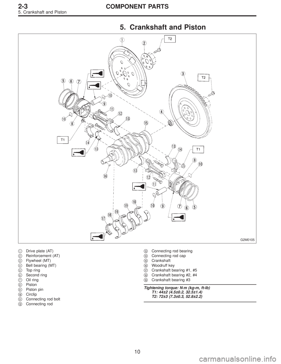
5. Crankshaft and Piston
G2M0105
�1Drive plate (AT)
�
2Reinforcement (AT)
�
3Flywheel (MT)
�
4Bell bearing (MT)
�
5Top ring
�
6Second ring
�
7Oil ring
�
8Piston
�
9Piston pin
�
10Circlip
�
11Connecting rod bolt
�
12Connecting rod�
13Connecting rod bearing
�
14Connecting rod cap
�
15Crankshaft
�
16Woodruff key
�
17Crankshaft bearing #1, #5
�
18Crankshaft bearing #2, #4
�
19Crankshaft bearing #3
Tightening torque: N⋅m (kg-m, ft-lb)
T1: 44±2 (4.5±0.2, 32.5±1.4)
T2: 72±3 (7.3±0.3, 52.8±2.2)
10
2-3COMPONENT PARTS
5. Crankshaft and Piston
Page 578 of 3342
 Damage of facing and ring gear
If defective, replace")
G2M0250
3. FLYWHEEL
CAUTION:
Since this bearing is grease sealed and is of a nonlu-
brication type, do not wash with gasoline or any sol-
vent.
1) Damage of facing and ring gear
If defective, replace flywheel.
G2M0251
2) Smoothness of rotation
Rotate ball bearing applying pressure in thrust direction.
If noise or excessive play is noted, replace ball bearing as
follows:
(1) Drive out ball bearing from flywheel.
(2) Press bearing into flywheel until bearing end sur-
face is flush with clutch disc contact surface of flywheel.
Do not press inner race.
ST 899754112 SNAP RING PRESS
B2M0331A
B2M0332A
C: INSTALLATION
1) Install flywheel.
2) Install ST, and tighten the flywheel attaching bolts to the
specified torque.
ST 498497100 CRANKSHAFT STOPPER
Tightening torque:
72±3 N⋅m (7.3±0.3 kg-m, 52.8±2.2 ft-lb)
NOTE:
Tighten flywheel installing bolts gradually. Each bolt should
be tightened to the specified torque in a crisscross fashion.
G2M0253
3) Insert ST into the clutch disc and install them on the
flywheel by inserting the ST end into the pilot bearing.
ST 499747100 CLUTCH DISC GUIDE
14
2-10SERVICE PROCEDURE
4. Clutch Disc and Cover
Page 579 of 3342
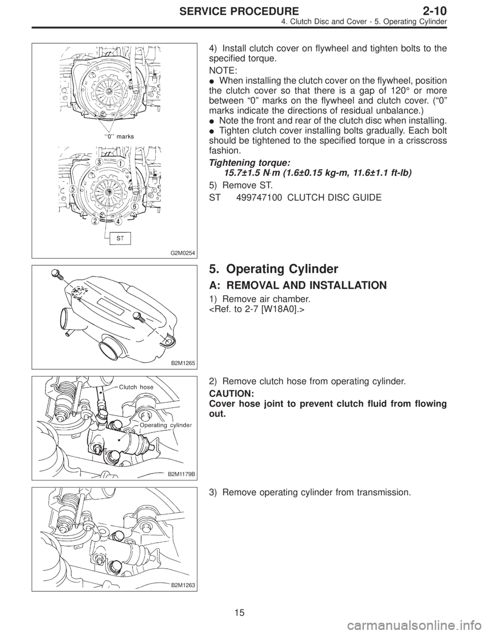
G2M0254
4) Install clutch cover on flywheel and tighten bolts to the
specified torque.
NOTE:
�When installing the clutch cover on the flywheel, position
the clutch cover so that there is a gap of 120°or more
between“0”marks on the flywheel and clutch cover. (“0”
marks indicate the directions of residual unbalance.)
�Note the front and rear of the clutch disc when installing.
�Tighten clutch cover installing bolts gradually. Each bolt
should be tightened to the specified torque in a crisscross
fashion.
Tightening torque:
15.7±1.5 N⋅m (1.6±0.15 kg-m, 11.6±1.1 ft-lb)
5) Remove ST.
ST 499747100 CLUTCH DISC GUIDE
B2M1265
5. Operating Cylinder
A: REMOVAL AND INSTALLATION
1) Remove air chamber.
B2M1179B
2) Remove clutch hose from operating cylinder.
CAUTION:
Cover hose joint to prevent clutch fluid from flowing
out.
B2M1263
3) Remove operating cylinder from transmission.
15
2-10SERVICE PROCEDURE
4. Clutch Disc and Cover - 5. Operating Cylinder
Page 580 of 3342
G2M0254
4) Install clutch cover on flywheel and tighten bolts to the
specified torque.
NOTE:
�When installing the clutch cover on the flywheel, position
the clutch cover so that there is a gap of 120°or more
between“0”marks on the flywheel and clutch cover. (“0”
marks indicate the directions of residual unbalance.)
�Note the front and rear of the clutch disc when installing.
�Tighten clutch cover installing bolts gradually. Each bolt
should be tightened to the specified torque in a crisscross
fashion.
Tightening torque:
15.7±1.5 N⋅m (1.6±0.15 kg-m, 11.6±1.1 ft-lb)
5) Remove ST.
ST 499747100 CLUTCH DISC GUIDE
B2M1265
5. Operating Cylinder
A: REMOVAL AND INSTALLATION
1) Remove air chamber.
B2M1179B
2) Remove clutch hose from operating cylinder.
CAUTION:
Cover hose joint to prevent clutch fluid from flowing
out.
B2M1263
3) Remove operating cylinder from transmission.
15
2-10SERVICE PROCEDURE
4. Clutch Disc and Cover - 5. Operating Cylinder
Page 1078 of 3342

1. Rear Differential
Symptom and possible cause Remedy
1. Oil leakage
�
1Worn, scratched, or incorrectly seated front or side oil seal.
Scored, battered, or excessively worn sliding surface of com-
panion flange.Repair or replace.
�
2Clogged or damaged air breather. Clean, repair or replace.
�
3Loose bolts on differential spindle or side retainer, or incor-
rectly fitted O-ring.Tighten bolts to specified torque. Replace O-ring.
�
4Loose rear cover attaching bolts or damaged gasket. Tighten bolts to specified torque. Replace gasket and apply liquid
packing.
�
5Loose oil filler or drain plug. Retighten and apply liquid packing.
�
6Wear, damage or incorrectly fitting for spindle, side retainer
and oil seal.Repair or replace.
2. Seizure
Seized or damaged parts should be replaced, and also other parts should be thoroughly checked for any defect and should be
repaired or replaced as required.
�
1Insufficient backlash for hypoid gear. Readjust or replace.
�
2Excessive preload for side, rear, or front bearing. Readjust or replace.
�
3Insufficient or improper oil used. Replace seized part and fill with specified oil to specified level.
3. Damage
Damaged parts should be replaced, and also other parts should be thoroughly checked for any defect and should be repaired or
replaced as required.
�
1Improper backlash for hypoid gear. Replace.
�
2Insufficient or excessive preload for side, rear, or front bear-
ing.Readjust or replace.
�
3Excessive backlash for differential gear. Replace gear or thrust washer.
�
4Loose bolts and nuts such as crown gear bolt. Retighten.
�
5Damage due to overloading. Replace.
4. Noises when starting or shifting gears
Noises may be caused by differential assembly, universal joint, wheel bearing, etc. Find out what is actually making noise before dis-
assembly.
�
1Excessive backlash for hypoid gear. Readjust.
�
2Excessive backlash for differential gear. Replace gear or thrust washer.
�
3Insufficient preload for front or rear bearing. Readjust.
�
4Loose drive pinion nut. Tighten to specified torque.
�
5Loose bolts and nuts such as side bearing retainer attaching
bolt.Tighten to specified torque.
40
3-4DIAGNOSTICS
1. Rear Differential
Page 1085 of 3342
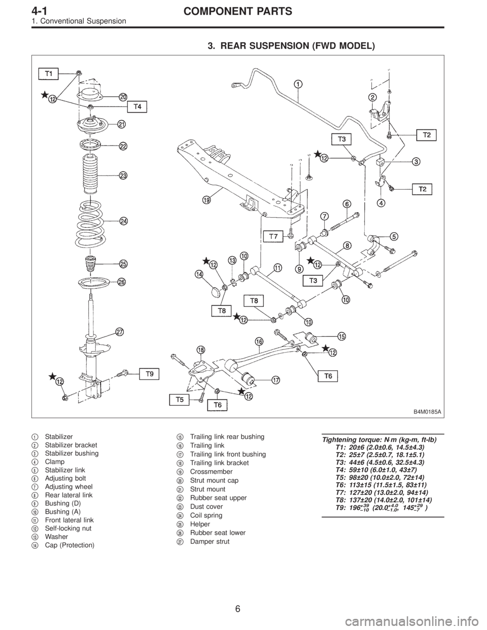
3. REAR SUSPENSION (FWD MODEL)
B4M0185A
�1Stabilizer
�
2Stabilizer bracket
�
3Stabilizer bushing
�
4Clamp
�
5Stabilizer link
�
6Adjusting bolt
�
7Adjusting wheel
�
8Rear lateral link
�
9Bushing (D)
�
10Bushing (A)
�
11Front lateral link
�
12Self-locking nut
�
13Washer
�
14Cap (Protection)�
15Trailing link rear bushing
�
16Trailing link
�
17Trailing link front bushing
�
18Trailing link bracket
�
19Crossmember
�
20Strut mount cap
�
21Strut mount
�
22Rubber seat upper
�
23Dust cover
�
24Coil spring
�
25Helper
�
26Rubber seat lower
�
27Damper strut
Tightening torque: N⋅m (kg-m, ft-lb)
T1: 20±6 (2.0±0.6, 14.5±4.3)
T2: 25±7 (2.5±0.7, 18.1±5.1)
T3: 44±6 (4.5±0.6, 32.5±4.3)
T4: 59±10 (6.0±1.0, 43±7)
T5: 98±20 (10.0±2.0, 72±14)
T6: 113±15 (11.5±1.5, 83±11)
T7: 127±20 (13.0±2.0, 94±14)
T8: 137±20 (14.0±2.0, 101±14)
T9: 196
+39
�10(20.0+4.0
�1.0, 145+29
�7)
6
4-1COMPONENT PARTS
1. Conventional Suspension
Page 1090 of 3342
 Loosen the left and right side steering tie-rods lock nuts.
2) Turn the left and right tie rods equal amounts until the
toe-in is at the specification.
Both the left and right t")
G4M0482
�Adjustment
1) Loosen the left and right side steering tie-rods lock nuts.
2) Turn the left and right tie rods equal amounts until the
toe-in is at the specification.
Both the left and right tie-rods are right-hand threaded. To
increase toe-in, turn both tie-rods clockwise equal amounts
(as viewed from the inside of the vehicle).
3) Tighten tie-rod lock nut.
Tightening torque:
83±5 N⋅m (8.5±0.5 kg-m, 61.5±3.6 ft-lb)
CAUTION:
Correct tie-rod boot, if it is twisted.
NOTE:
Check the left and right wheel steering angle is within
specifications.
M4A0059
4. REAR WHEEL TOE-IN (FWD MODEL)
�Inspection
1) Using a toe-in gauge, measure rear wheel toe-in.
Toe-in: 0±3 mm (0±0.12 in)
2) Mark rear sides of left and right tires at height corre-
sponding to center of spindles and measure distance“B”
between marks.
3) Move vehicle forward so that marks line up with front
sides at height corresponding to center of spindles.
4) Measure distance“A”between left and right marks.
Toe-in can then be obtained by the following equation:
B�A = Toe-in
G4M0483
�Adjustment
1) Remove cap from lateral link and loosen self-locking
nut.
CAUTION:
�When loosening or tightening adjusting bolt, hold
the bolt head and loosen self-locking nut.
�Replace self-locking nut with a new one.
2) Using two wrenches, turn adjusting wheel and adjusting
bolt equally in opposite directions so that toe-in is at the
specification.
11
4-1SERVICE PROCEDURE
1. On-car Services