Page 1121 of 3342
 Install strut mount cap.
2) Tighten self-locking nut used to secure strut mount to
vehicle body.
CAUTION:
Use a new self-locking nut.
NOTE:
Tighten strut mount and cap as a unit.
Ti")
E: INSTALLATION
1) Install strut mount cap.
2) Tighten self-locking nut used to secure strut mount to
vehicle body.
CAUTION:
Use a new self-locking nut.
NOTE:
Tighten strut mount and cap as a unit.
Tightening torque:
20±6 N⋅m (2.0±0.6 kg-m, 14.5±4.3 ft-lb)
3) Tighten bolts securing rear strut to housing.
Tightening torque:
196
+39
�10N⋅m (20.0+4.0
�1.0kg-m, 145+29
�7ft-lb)
CAUTION:
Use a new self-locking nut.
4) Models with rear disc brakes:
Tighten brake hose union bolt on brake caliper.
Tightening torque:
18±3 N⋅m (1.8±0.3 kg-m, 13.0±2.2 ft-lb)
Models with rear drum brakes:
Connect brake hose to brake pipe.
Tightening torque:
15
+3
�2N⋅m (1.5+0.3
�0.2kg-m, 10.8+2.2
�1.4ft-lb)
5) Insert brake hose clip between brake hose and lower
side of strut.
CAUTION:
�Check that hose clip is positioned properly.
�Check brake hose for twisting, or excessive tension.
�Models equipped with A.B.S.:
Do not subject A.B.S. sensor harness to excessive ten-
sion.
6) Be sure to bleed air from brake system.
7) Lower vehicle and tighten wheel nut.
Tightening torque:
88±10 N⋅m (9±1 kg-m, 65±7 ft-lb)
8) Sedan:
Install rear seat backrest and rear seat cushion.
Wagon:
Install strut cap of rear quarter trim.
NOTE:
Check wheel alignment and adjust if necessary.
42
4-1SERVICE PROCEDURE
9. Rear Strut
Page 1122 of 3342
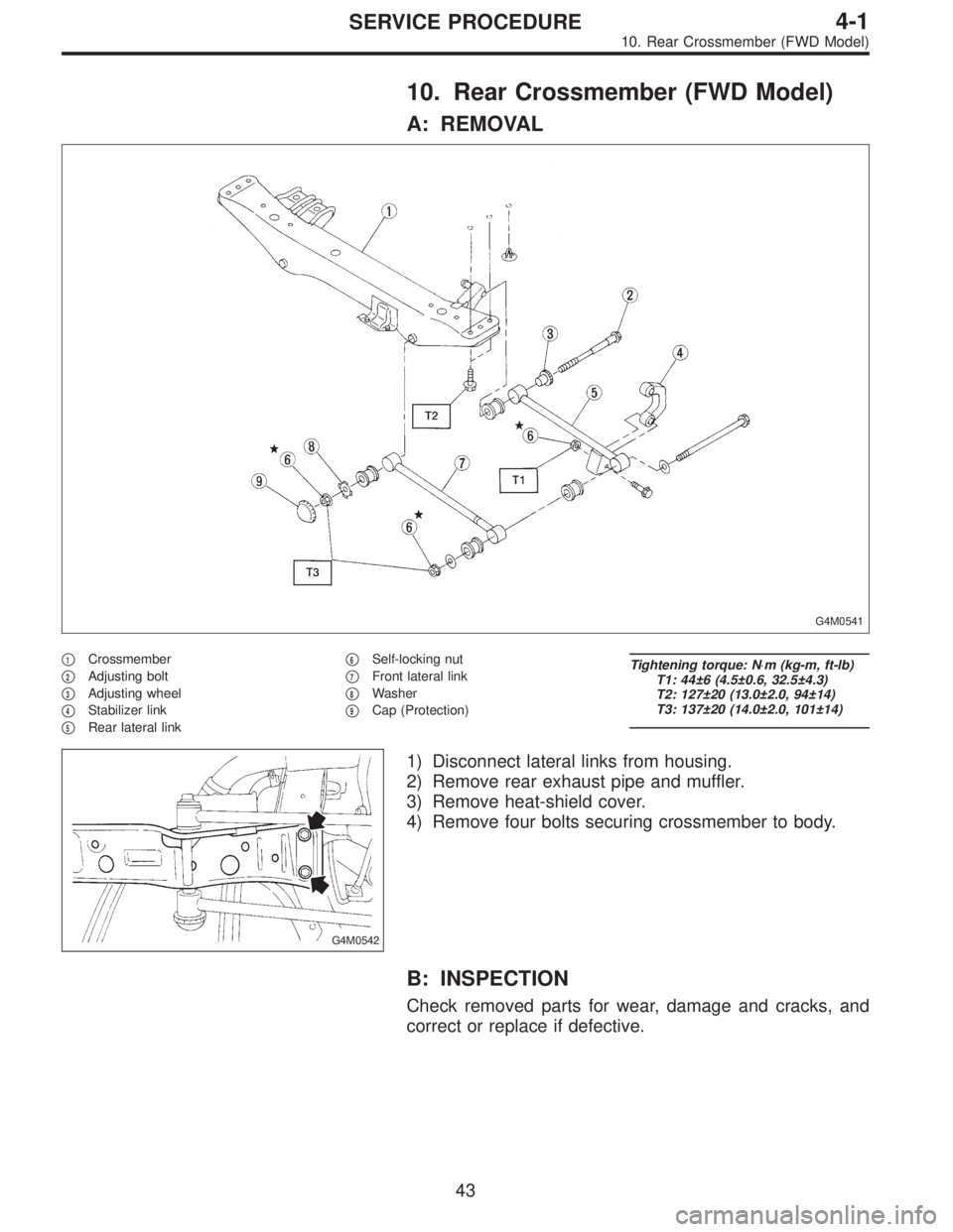
10. Rear Crossmember (FWD Model)
A: REMOVAL
G4M0541
�1Crossmember
�
2Adjusting bolt
�
3Adjusting wheel
�
4Stabilizer link
�
5Rear lateral link�
6Self-locking nut
�
7Front lateral link
�
8Washer
�
9Cap (Protection)
Tightening torque: N⋅m (kg-m, ft-lb)
T1: 44±6 (4.5±0.6, 32.5±4.3)
T2: 127±20 (13.0±2.0, 94±14)
T3: 137±20 (14.0±2.0, 101±14)
G4M0542
1) Disconnect lateral links from housing.
2) Remove rear exhaust pipe and muffler.
3) Remove heat-shield cover.
4) Remove four bolts securing crossmember to body.
B: INSPECTION
Check removed parts for wear, damage and cracks, and
correct or replace if defective.
43
4-1SERVICE PROCEDURE
10. Rear Crossmember (FWD Model)
Page 1125 of 3342
G4M0544
5) Place transmission jack under rear crossmember.
G4M0545
6) Remove bolts securing crossmember to vehicle body,
and remove crossmember.
7) Scribe an alignment mark on rear lateral link cam bolt
and crossmember.
8) Remove four bolts securing front and rear lateral links
to crossmember by loosening nuts.
B: INSPECTION
Check removed parts for damage and cracks, and correct
or replace if defective.
C: INSTALLATION
1) Install in reverse order of removal.
2) For installation and tightening torque of rear differential,
refer to 3-4 [W2F0].
CAUTION:
Always tighten rubber bushing when wheels are in full
contact with the ground and vehicle is at curb weight
condition.
NOTE:
Check wheel alignment and adjust if necessary.
46
4-1SERVICE PROCEDURE
11. Rear Crossmember (AWD Model)
Page 1126 of 3342
 Permanent distortion or breakage of coil spring Replace.
(2) Unsmooth operation of damper st")
1. Suspension
1. IMPROPER VEHICLE POSTURE OR IMPROPER
WHEEL ARCH HEIGHT
Possible causes Countermeasures
(1) Permanent distortion or breakage of coil spring Replace.
(2) Unsmooth operation of damper strut Replace.
(3) Installation of wrong strut Replace with proper parts.
(4) Installation of wrong coil spring Replace with proper parts.
2. POOR RIDE COMFORT
1) Large rebound shock
2) Rocking of vehicle continues too long after running over
bump and/or hump.
3) Large shock in bumping
Possible causes Countermeasures
(1) Breakage of coil spring Replace.
(2) Over-inflation pressure of tire Adjust.
(3) Improper wheel arch height Adjust or replace coil springs with new ones.
(4) Fault in operation of damper strut Replace.
(5) Damage or deformation of strut mount Replace.
(6) Unsuitability of maximum and/or minimum length of
damper strutReplace with proper parts.
(7) Deformation or loss of bushing Replace.
(8) Deformation or damage of helper in strut assembly Replace.
(9) Oil leakage of damper strut Replace.
3. NOISE
Possible causes Countermeasures
(1) Wear or damage of damper strut component parts Replace.
(2) Loosening of suspension link installing bolt and/or nut Retighten to the specified torque.
(3) Deformation or loss of bushing Replace.
(4) Unsuitability of maximum and/or minimum length of
damper strutReplace with proper parts.
(5) Breakage of coil spring Replace.
(6) Wear or damage of ball joint Replace.
(7) Deformation of stabilizer clamp Replace.
47
4-1DIAGNOSTICS
1. Suspension
Page 1130 of 3342
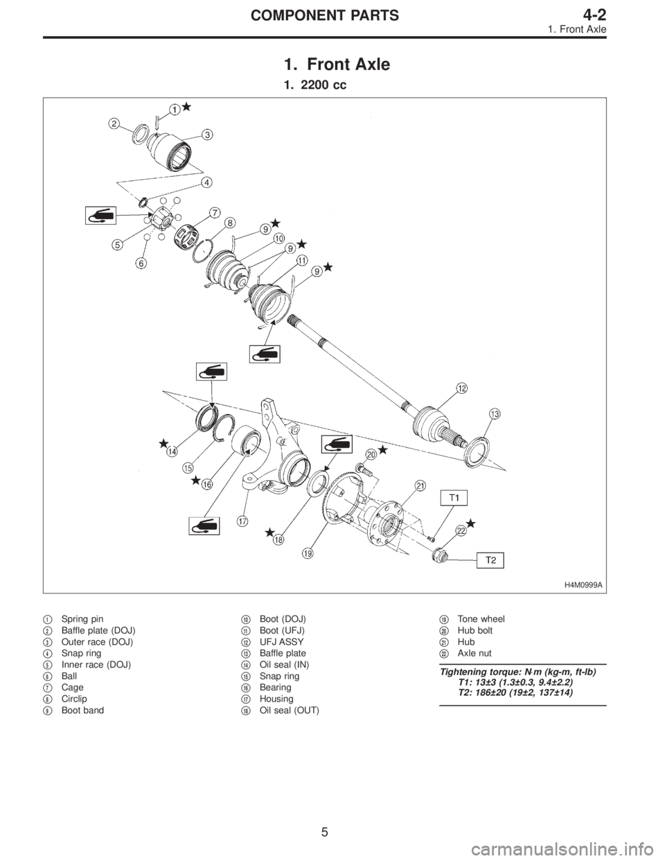
1. Front Axle
1. 2200 cc
H4M0999A
�1Spring pin
�
2Baffle plate (DOJ)
�
3Outer race (DOJ)
�
4Snap ring
�
5Inner race (DOJ)
�
6Ball
�
7Cage
�
8Circlip
�
9Boot band�
10Boot (DOJ)
�
11Boot (UFJ)
�
12UFJ ASSY
�
13Baffle plate
�
14Oil seal (IN)
�
15Snap ring
�
16Bearing
�
17Housing
�
18Oil seal (OUT)�
19Tone wheel
�
20Hub bolt
�
21Hub
�
22Axle nut
Tightening torque: N⋅m (kg-m, ft-lb)
T1: 13±3 (1.3±0.3, 9.4±2.2)
T2: 186±20 (19±2, 137±14)
5
4-2COMPONENT PARTS
1. Front Axle
Page 1131 of 3342
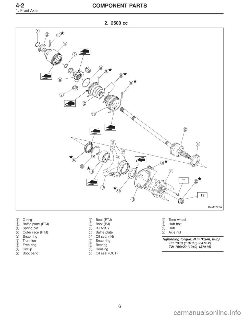
2. 2500 cc
B4M0773A
�1O-ring
�
2Baffle plate (FTJ)
�
3Spring pin
�
4Outer race (FTJ)
�
5Snap ring
�
6Trunnion
�
7Free ring
�
8Circlip
�
9Boot band�
10Boot (FTJ)
�
11Boot (BJ)
�
12BJ ASSY
�
13Baffle plate
�
14Oil seal (IN)
�
15Snap ring
�
16Bearing
�
17Housing
�
18Oil seal (OUT)�
19Tone wheel
�
20Hub bolt
�
21Hub
�
22Axle nut
Tightening torque: N⋅m (kg-m, ft-lb)
T1: 13±3 (1.3±0.3, 9.4±2.2)
T2: 186±20 (19±2, 137±14)
6
4-2COMPONENT PARTS
1. Front Axle
Page 1132 of 3342
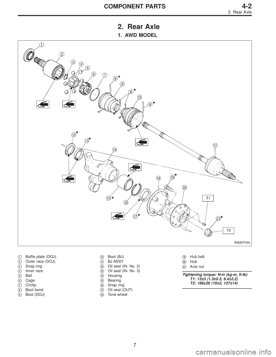
2. Rear Axle
1. AWD MODEL
B4M0704A
�1Baffle plate (DOJ)
�
2Outer race (DOJ)
�
3Snap ring
�
4Inner race
�
5Ball
�
6Cage
�
7Circlip
�
8Boot band
�
9Boot (DOJ)�
10Boot (BJ)
�
11BJ ASSY
�
12Oil seal (IN. No. 2)
�
13Oil seal (IN. No. 3)
�
14Housing
�
15Bearing
�
16Snap ring
�
17Oil seal (OUT)
�
18Tone wheel�
19Hub bolt
�
20Hub
�
21Axle nut
Tightening torque: N⋅m (kg-m, ft-lb)
T1: 13±3 (1.3±0.3, 9.4±2.2)
T2: 186±20 (19±2, 137±14)
7
4-2COMPONENT PARTS
2. Rear Axle
Page 1140 of 3342
 Install transverse link ball joint to housing.
Tightening torque:
44±6 N⋅m (4.5±0.6 kg-m, 32.5±4.3 ft-lb)
2) While aligning alignment mark on camber adjusting bolt
head, connec")
E: INSTALLATION
1) Install transverse link ball joint to housing.
Tightening torque:
44±6 N⋅m (4.5±0.6 kg-m, 32.5±4.3 ft-lb)
2) While aligning alignment mark on camber adjusting bolt
head, connect housing and strut.
CAUTION:
Use a new self-locking nut.
Tightening torque:
147±15 N⋅m (15±1.5 kg-m, 108±11 ft-lb)
3) Install speed sensor and harness on housing (only
vehicle equipped with A.B.S.).
4) Install disc rotor on hub.
5) Install disc brake caliper on housing.
Tightening torque:
59±10 N⋅m (6±1 kg-m, 43±7 ft-lb)
6) Install front drive shaft.
7) Connect stabilizer link.
G4M0236
8) Install tie-rod end ball joint on housing knuckle arm.
Tightening torque:
27.0±2.5 N⋅m (2.75±0.25 kg-m, 19.9±1.8 ft-lb)
G4M0237
9) While depressing brake pedal, tighten axle nut and lock
it securely.
Tightening torque:
186±20 N⋅m (19±2 kg-m, 137±14 ft-lb)
CAUTION:
�Use a new axle nut.
�Always tighten axle nut before installing wheel on
vehicle. If wheel is installed and comes in contact with
ground when axle nut is loose, wheel bearings may be
damaged.
�Be sure to tighten axle nut to specified torque. Do
not overtighten it as this may damage wheel bearing.
15
4-2SERVICE PROCEDURE
1. Front Axle
 Place transmission jack under rear crossmember.
G4M0545
6) Remove bolts securing crossmember to vehicle body,
and remove crossmember.
7) Scribe an alignment mark on rear lateral link cam bo")