Page 1342 of 3342
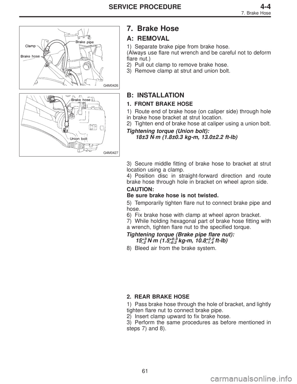
G4M0426
7. Brake Hose
A: REMOVAL
1) Separate brake pipe from brake hose.
(Always use flare nut wrench and be careful not to deform
flare nut.)
2) Pull out clamp to remove brake hose.
3) Remove clamp at strut and union bolt.
G4M0427
B: INSTALLATION
1. FRONT BRAKE HOSE
1) Route end of brake hose (on caliper side) through hole
in brake hose bracket at strut location.
2) Tighten end of brake hose at caliper using a union bolt.
Tightening torque (Union bolt):
18±3 N⋅m (1.8±0.3 kg-m, 13.0±2.2 ft-lb)
3) Secure middle fitting of brake hose to bracket at strut
location using a clamp.
4) Position disc in straight-forward direction and route
brake hose through hole in bracket on wheel apron side.
CAUTION:
Be sure brake hose is not twisted.
5) Temporarily tighten flare nut to connect brake pipe and
hose.
6) Fix brake hose with clamp at wheel apron bracket.
7) While holding hexagonal part of brake hose fitting with
a wrench, tighten flare nut to the specified torque.
Tightening torque (Brake pipe flare nut):
15
+3
�2N⋅m (1.5+0.3
�0.2kg-m, 10.8+2.2
�1.4ft-lb)
8) Bleed air from the brake system.
2. REAR BRAKE HOSE
1) Pass brake hose through the hole of bracket, and lightly
tighten flare nut to connect brake pipe.
2) Insert clamp upward to fix brake hose.
3) Perform the same procedures as before mentioned in
steps 7) and 8).
61
4-4SERVICE PROCEDURE
7. Brake Hose
Page 1418 of 3342
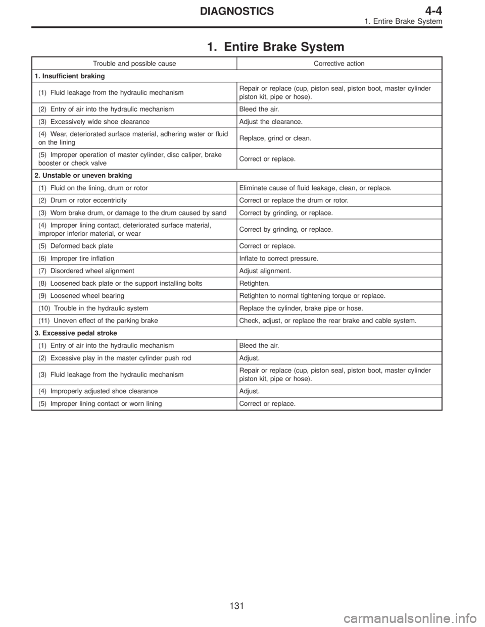
1. Entire Brake System
Trouble and possible cause Corrective action
1. Insufficient braking
(1) Fluid leakage from the hydraulic mechanismRepair or replace (cup, piston seal, piston boot, master cylinder
piston kit, pipe or hose).
(2) Entry of air into the hydraulic mechanism Bleed the air.
(3) Excessively wide shoe clearance Adjust the clearance.
(4) Wear, deteriorated surface material, adhering water or fluid
on the liningReplace, grind or clean.
(5) Improper operation of master cylinder, disc caliper, brake
booster or check valveCorrect or replace.
2. Unstable or uneven braking
(1) Fluid on the lining, drum or rotor Eliminate cause of fluid leakage, clean, or replace.
(2) Drum or rotor eccentricity Correct or replace the drum or rotor.
(3) Worn brake drum, or damage to the drum caused by sand Correct by grinding, or replace.
(4) Improper lining contact, deteriorated surface material,
improper inferior material, or wearCorrect by grinding, or replace.
(5) Deformed back plate Correct or replace.
(6) Improper tire inflation Inflate to correct pressure.
(7) Disordered wheel alignment Adjust alignment.
(8) Loosened back plate or the support installing bolts Retighten.
(9) Loosened wheel bearing Retighten to normal tightening torque or replace.
(10) Trouble in the hydraulic system Replace the cylinder, brake pipe or hose.
(11) Uneven effect of the parking brake Check, adjust, or replace the rear brake and cable system.
3. Excessive pedal stroke
(1) Entry of air into the hydraulic mechanism Bleed the air.
(2) Excessive play in the master cylinder push rod Adjust.
(3) Fluid leakage from the hydraulic mechanismRepair or replace (cup, piston seal, piston boot, master cylinder
piston kit, pipe or hose).
(4) Improperly adjusted shoe clearance Adjust.
(5) Improper lining contact or worn lining Correct or replace.
131
4-4DIAGNOSTICS
1. Entire Brake System
Page 1419 of 3342
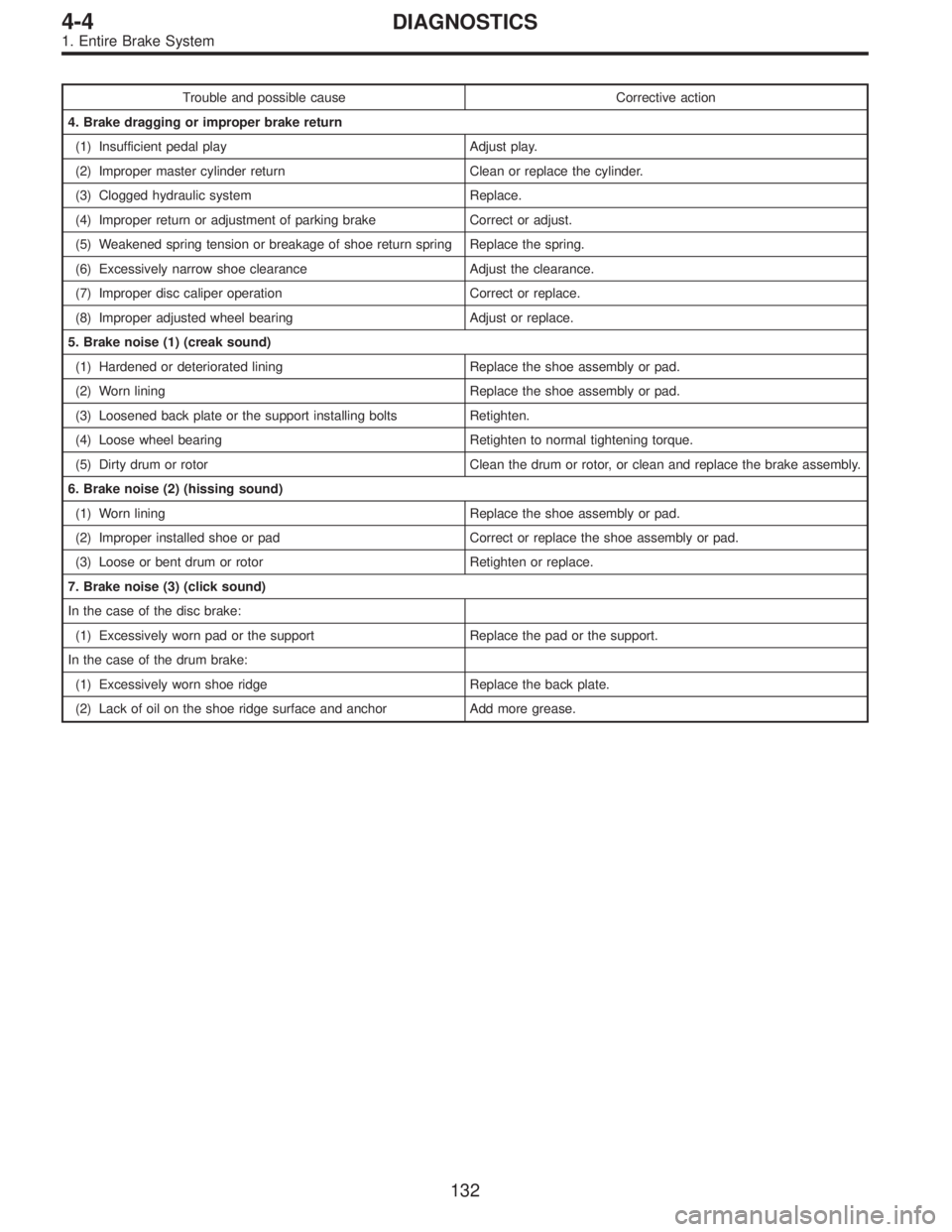
Trouble and possible cause Corrective action
4. Brake dragging or improper brake return
(1) Insufficient pedal play Adjust play.
(2) Improper master cylinder return Clean or replace the cylinder.
(3) Clogged hydraulic system Replace.
(4) Improper return or adjustment of parking brake Correct or adjust.
(5) Weakened spring tension or breakage of shoe return spring Replace the spring.
(6) Excessively narrow shoe clearance Adjust the clearance.
(7) Improper disc caliper operation Correct or replace.
(8) Improper adjusted wheel bearing Adjust or replace.
5. Brake noise (1) (creak sound)
(1) Hardened or deteriorated lining Replace the shoe assembly or pad.
(2) Worn lining Replace the shoe assembly or pad.
(3) Loosened back plate or the support installing bolts Retighten.
(4) Loose wheel bearing Retighten to normal tightening torque.
(5) Dirty drum or rotor Clean the drum or rotor, or clean and replace the brake assembly.
6. Brake noise (2) (hissing sound)
(1) Worn lining Replace the shoe assembly or pad.
(2) Improper installed shoe or pad Correct or replace the shoe assembly or pad.
(3) Loose or bent drum or rotor Retighten or replace.
7. Brake noise (3) (click sound)
In the case of the disc brake:
(1) Excessively worn pad or the support Replace the pad or the support.
In the case of the drum brake:
(1) Excessively worn shoe ridge Replace the back plate.
(2) Lack of oil on the shoe ridge surface and anchor Add more grease.
132
4-4DIAGNOSTICS
1. Entire Brake System
Page 2637 of 3342
8B5CHECK ABS SENSOR MECHANICAL
TROUBLE.
: Tightening torque:
32±10 N⋅m (3.3±1.0 kg-m, 24±7 ft-lb)
Are the ABS sensor installation bolts tight-
ened securely?
: Go to next.
: Tighten ABS sensor installation bolts securely.
: Tightening torque:
13±3 N⋅m (1.3±0.3 kg-m, 9±2.2 ft-lb)
Are the tone wheel installation bolts tight-
ened securely?
: Go to next step.
: Tighten tone wheel installation bolts securely.
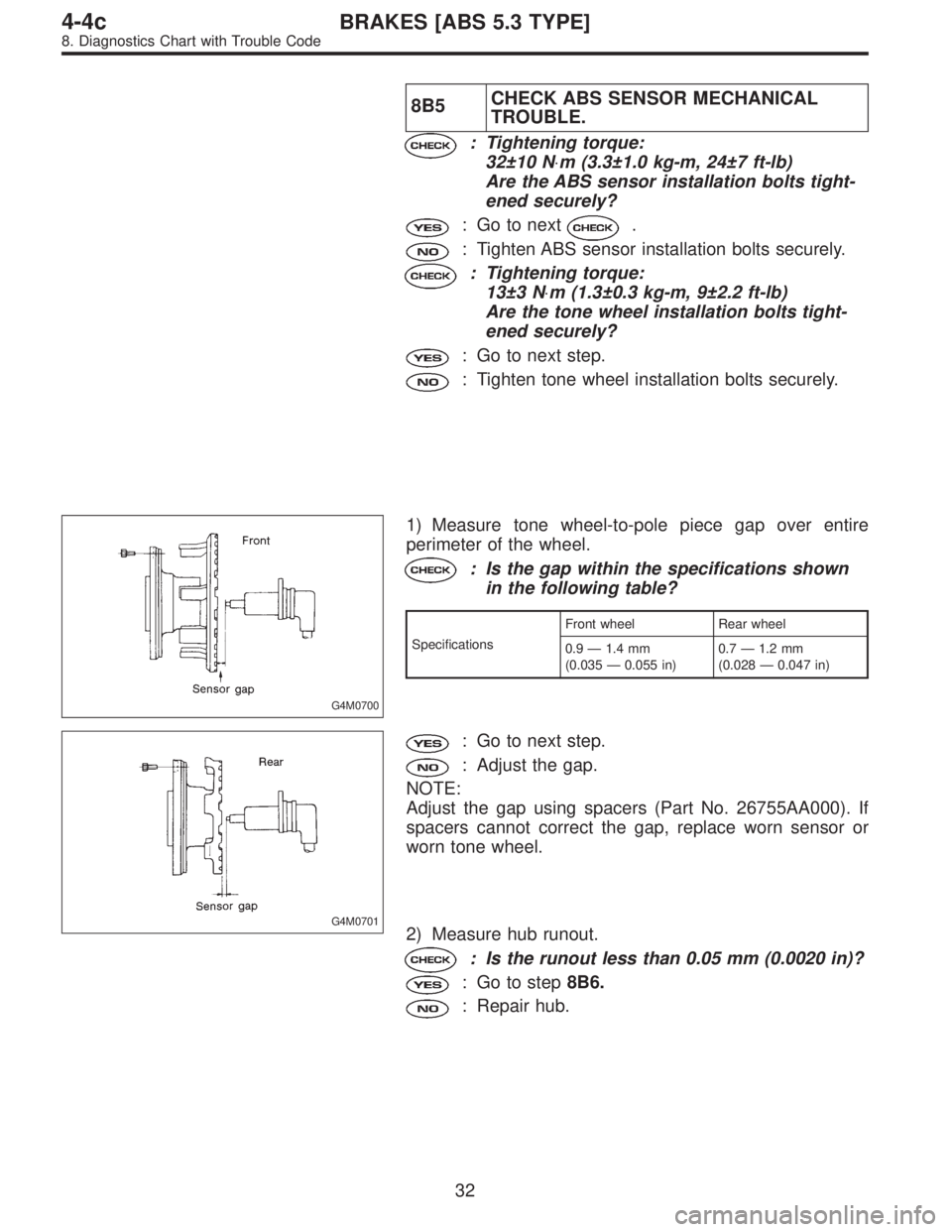
G4M0700
1) Measure tone wheel-to-pole piece gap over entire
perimeter of the wheel.
: Is the gap within the specifications shown
in the following table?
SpecificationsFront wheel Rear wheel
0.9—1.4 mm
(0.035—0.055 in)0.7—1.2 mm
(0.028—0.047 in)
G4M0701
: Go to next step.
: Adjust the gap.
NOTE:
Adjust the gap using spacers (Part No. 26755AA000). If
spacers cannot correct the gap, replace worn sensor or
worn tone wheel.
2) Measure hub runout.
: Is the runout less than 0.05 mm (0.0020 in)?
: Go to step8B6.
: Repair hub.
32
4-4cBRAKES [ABS 5.3 TYPE]
8. Diagnostics Chart with Trouble Code
Page 2640 of 3342
WIRING DIAGRAM:
B4M1035
8C1CHECK ABS SENSOR MECHANICAL
TROUBLE.
: Tightening torque:
32±10 N⋅m (3.3±1.0 kg-m, 24±7 ft-lb)
Are the ABS sensor installation bolts tight-
ened securely?
: Go to next.
: Tighten ABS sensor installation bolts securely.
: Tightening torque:
13±3 N⋅m (1.3±0.3 kg-m, 9±2.2 ft-lb)
Are the tone wheel installation bolts tight-
ened securely?
: Go to next step.
: Tighten tone wheel installation bolts securely.
35
4-4cBRAKES [ABS 5.3 TYPE]
8. Diagnostics Chart with Trouble Code
Page 2649 of 3342
8D2
CHECK TIRE.
: Are the tire specifications correct?
: Go to next.
: Replace tire.
: Is the tire worn excessively?
: Replace tire.
: Go to next.
: Is the tire pressure correct?
: Go to step8D3.
: Adjust tire pressure.
8D3CHECK ABS SENSOR MECHANICAL
TROUBLE.
: Tightening torque:
32±10 N⋅m (3.3±1.0 kg-m, 24±7 ft-lb)
Are the ABS sensor installation bolts tight-
ened securely?
: Go to next.
: Tighten ABS sensor installation bolts securely.
: Tightening torque:
13±3 N⋅m (1.3±0.3 kg-m, 9±2.2 ft-lb)
Are the tone wheel installation bolts tight-
ened securely?
: Go to next step.
: Tighten tone wheel installation bolts securely.
G4M0700
1) Measure tone wheel to pole piece gap over entire
perimeter of the wheel.
: Is the gap within the specifications shown
in the following table?
SpecificationsFront wheel Rear wheel
0.9—1.4 mm
(0.035—0.055 in)0.7—1.2 mm
(0.028—0.047 in)
44
4-4cBRAKES [ABS 5.3 TYPE]
8. Diagnostics Chart with Trouble Code
Page 2740 of 3342
B4M0922
10H1CHECK OUTPUT OF ABS SENSOR
USING SELECT MONITOR.
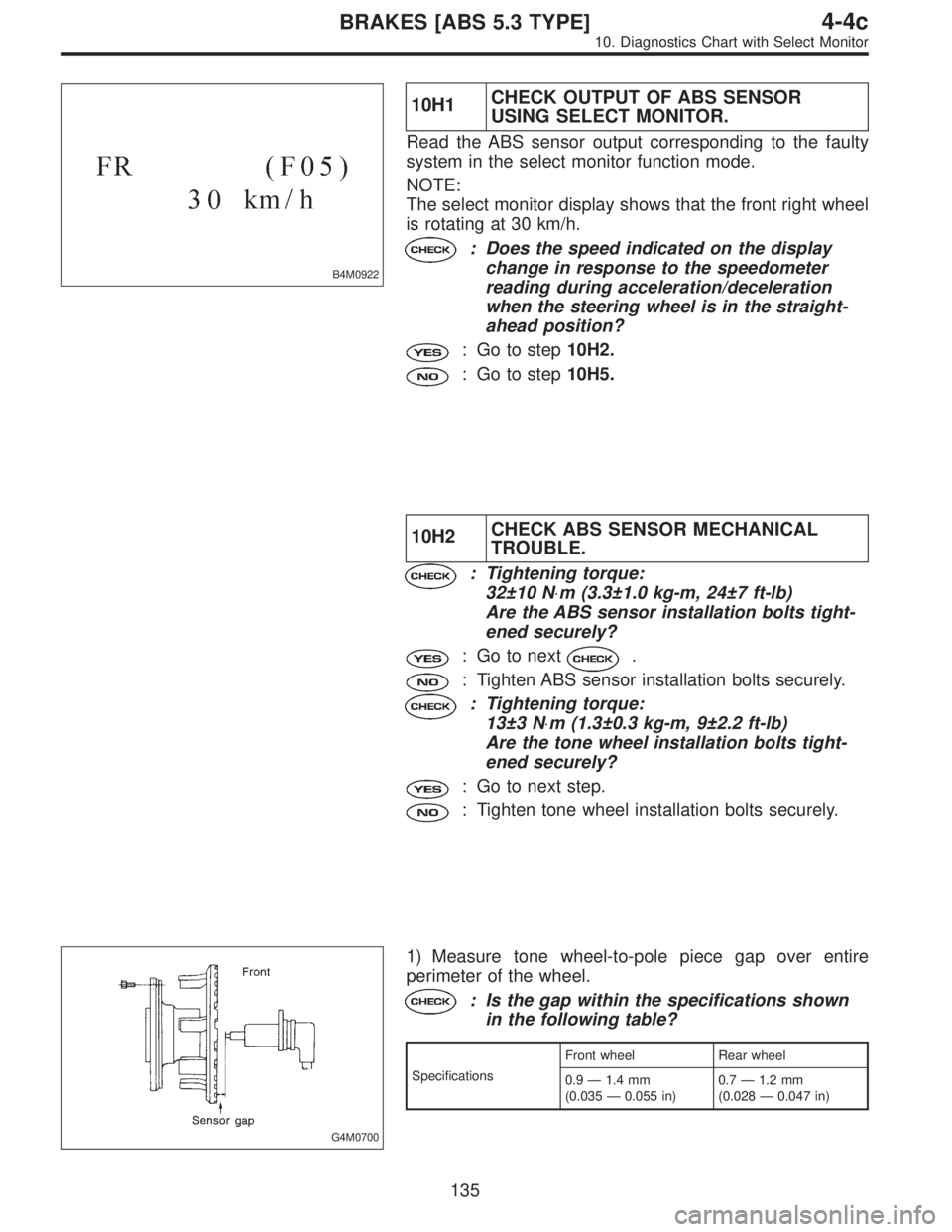
Read the ABS sensor output corresponding to the faulty
system in the select monitor function mode.
NOTE:
The select monitor display shows that the front right wheel
is rotating at 30 km/h.
: Does the speed indicated on the display
change in response to the speedometer
reading during acceleration/deceleration
when the steering wheel is in the straight-
ahead position?
: Go to step10H2.
: Go to step10H5.
10H2CHECK ABS SENSOR MECHANICAL
TROUBLE.
: Tightening torque:
32±10 N⋅m (3.3±1.0 kg-m, 24±7 ft-lb)
Are the ABS sensor installation bolts tight-
ened securely?
: Go to next.
: Tighten ABS sensor installation bolts securely.
: Tightening torque:
13±3 N⋅m (1.3±0.3 kg-m, 9±2.2 ft-lb)
Are the tone wheel installation bolts tight-
ened securely?
: Go to next step.
: Tighten tone wheel installation bolts securely.
G4M0700
1) Measure tone wheel-to-pole piece gap over entire
perimeter of the wheel.
: Is the gap within the specifications shown
in the following table?
SpecificationsFront wheel Rear wheel
0.9—1.4 mm
(0.035—0.055 in)0.7—1.2 mm
(0.028—0.047 in)
135
4-4cBRAKES [ABS 5.3 TYPE]
10. Diagnostics Chart with Select Monitor
Page 2744 of 3342
10H9CHECK ABS SENSOR MECHANICAL
TROUBLE.
: Tightening torque:
32±10 N⋅m (3.3±1.0 kg-m, 24±7 ft-lb)
Are the ABS sensor installation bolts tight-
ened securely?
: Go to next.
: Tighten ABS sensor installation bolts securely.
: Tightening torque:
13±3 N⋅m (1.3±0.3 kg-m, 9±2.2 ft-lb)
Are the tone wheel installation bolts tight-
ened securely?
: Go to next step.
: Tighten tone wheel installation bolts securely.
G4M0700
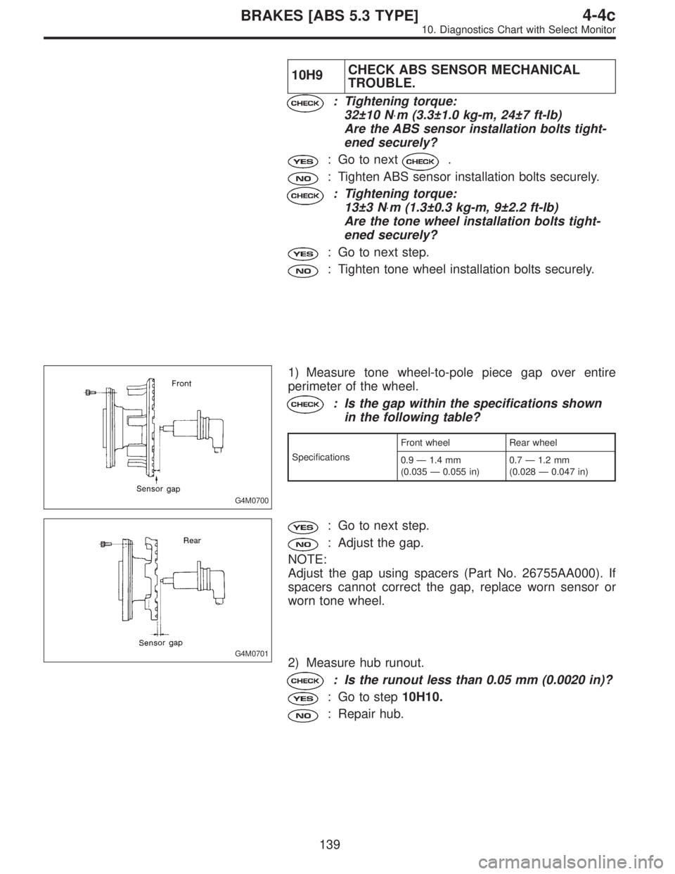
1) Measure tone wheel-to-pole piece gap over entire
perimeter of the wheel.
: Is the gap within the specifications shown
in the following table?
SpecificationsFront wheel Rear wheel
0.9—1.4 mm
(0.035—0.055 in)0.7—1.2 mm
(0.028—0.047 in)
G4M0701
: Go to next step.
: Adjust the gap.
NOTE:
Adjust the gap using spacers (Part No. 26755AA000). If
spacers cannot correct the gap, replace worn sensor or
worn tone wheel.
2) Measure hub runout.
: Is the runout less than 0.05 mm (0.0020 in)?
: Go to step10H10.
: Repair hub.
139
4-4cBRAKES [ABS 5.3 TYPE]
10. Diagnostics Chart with Select Monitor