Page 1141 of 3342
G4M0238
10) After tightening axle nut, lock it securely.
11) Install wheel and tighten wheel nuts to specified
torque.
Tightening torque:
88±10 N⋅m (9±1 kg-m, 65±7 ft-lb)
2. Rear Axle (AWD Model)
A: REMOVAL
1) Disconnect ground cable from battery.
2) Jack-up vehicle, and remove rear wheel cap and
wheels.
CAUTION:
Be sure to loosen and retighten axle nut after remov-
ing wheel from vehicle. Failure to follow this rule may
damage wheel bearings.
3) Unlock axle nut.
4) Remove axle nut using a socket wrench.
B4M0050A
5) Return parking brake lever and loosen adjusting nut.
(1) Disc brake: Perform steps 6) and 7).
(2) Drum brake: Perform steps 8) through 10).
G4M0240
6) Remove disc brake caliper from back plate, and sus-
pend it from strut using a piece of wire.
7) Remove disc rotor from hub.
NOTE:
If disc rotor seizes up within hub, drive it out by installing
an 8-mm bolt into bolt hole in disc rotor.
16
4-2SERVICE PROCEDURE
1. Front Axle - 2. Rear Axle (AWD Model)
Page 1142 of 3342
G4M0238
10) After tightening axle nut, lock it securely.
11) Install wheel and tighten wheel nuts to specified
torque.
Tightening torque:
88±10 N⋅m (9±1 kg-m, 65±7 ft-lb)
2. Rear Axle (AWD Model)
A: REMOVAL
1) Disconnect ground cable from battery.
2) Jack-up vehicle, and remove rear wheel cap and
wheels.
CAUTION:
Be sure to loosen and retighten axle nut after remov-
ing wheel from vehicle. Failure to follow this rule may
damage wheel bearings.
3) Unlock axle nut.
4) Remove axle nut using a socket wrench.
B4M0050A
5) Return parking brake lever and loosen adjusting nut.
(1) Disc brake: Perform steps 6) and 7).
(2) Drum brake: Perform steps 8) through 10).
G4M0240
6) Remove disc brake caliper from back plate, and sus-
pend it from strut using a piece of wire.
7) Remove disc rotor from hub.
NOTE:
If disc rotor seizes up within hub, drive it out by installing
an 8-mm bolt into bolt hole in disc rotor.
16
4-2SERVICE PROCEDURE
1. Front Axle - 2. Rear Axle (AWD Model)
Page 1180 of 3342
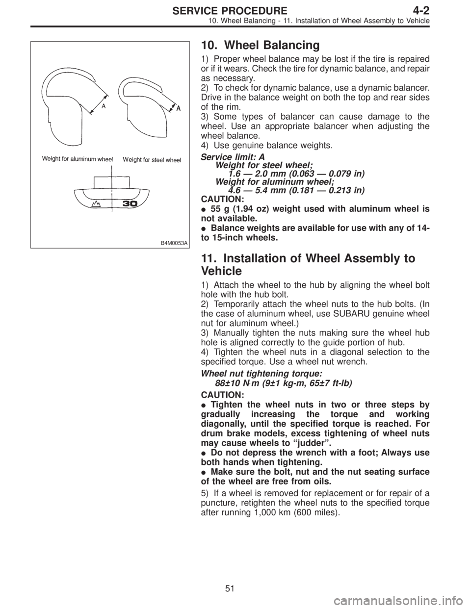
B4M0053A
10. Wheel Balancing
1) Proper wheel balance may be lost if the tire is repaired
or if it wears. Check the tire for dynamic balance, and repair
as necessary.
2) To check for dynamic balance, use a dynamic balancer.
Drive in the balance weight on both the top and rear sides
of the rim.
3) Some types of balancer can cause damage to the
wheel. Use an appropriate balancer when adjusting the
wheel balance.
4) Use genuine balance weights.
Service limit: A
Weight for steel wheel;
1.6—2.0 mm (0.063—0.079 in)
Weight for aluminum wheel;
4.6—5.4 mm (0.181—0.213 in)
CAUTION:
�55 g (1.94 oz) weight used with aluminum wheel is
not available.
�Balance weights are available for use with any of 14-
to 15-inch wheels.
11. Installation of Wheel Assembly to
Vehicle
1) Attach the wheel to the hub by aligning the wheel bolt
hole with the hub bolt.
2) Temporarily attach the wheel nuts to the hub bolts. (In
the case of aluminum wheel, use SUBARU genuine wheel
nut for aluminum wheel.)
3) Manually tighten the nuts making sure the wheel hub
hole is aligned correctly to the guide portion of hub.
4) Tighten the wheel nuts in a diagonal selection to the
specified torque. Use a wheel nut wrench.
Wheel nut tightening torque:
88±10 N⋅m (9±1 kg-m, 65±7 ft-lb)
CAUTION:
�Tighten the wheel nuts in two or three steps by
gradually increasing the torque and working
diagonally, until the specified torque is reached. For
drum brake models, excess tightening of wheel nuts
may cause wheels to “judder”.
�Do not depress the wrench with a foot; Always use
both hands when tightening.
�Make sure the bolt, nut and the nut seating surface
of the wheel are free from oils.
5) If a wheel is removed for replacement or for repair of a
puncture, retighten the wheel nuts to the specified torque
after running 1,000 km (600 miles).
51
4-2SERVICE PROCEDURE
10. Wheel Balancing - 11. Installation of Wheel Assembly to Vehicle
Page 1181 of 3342
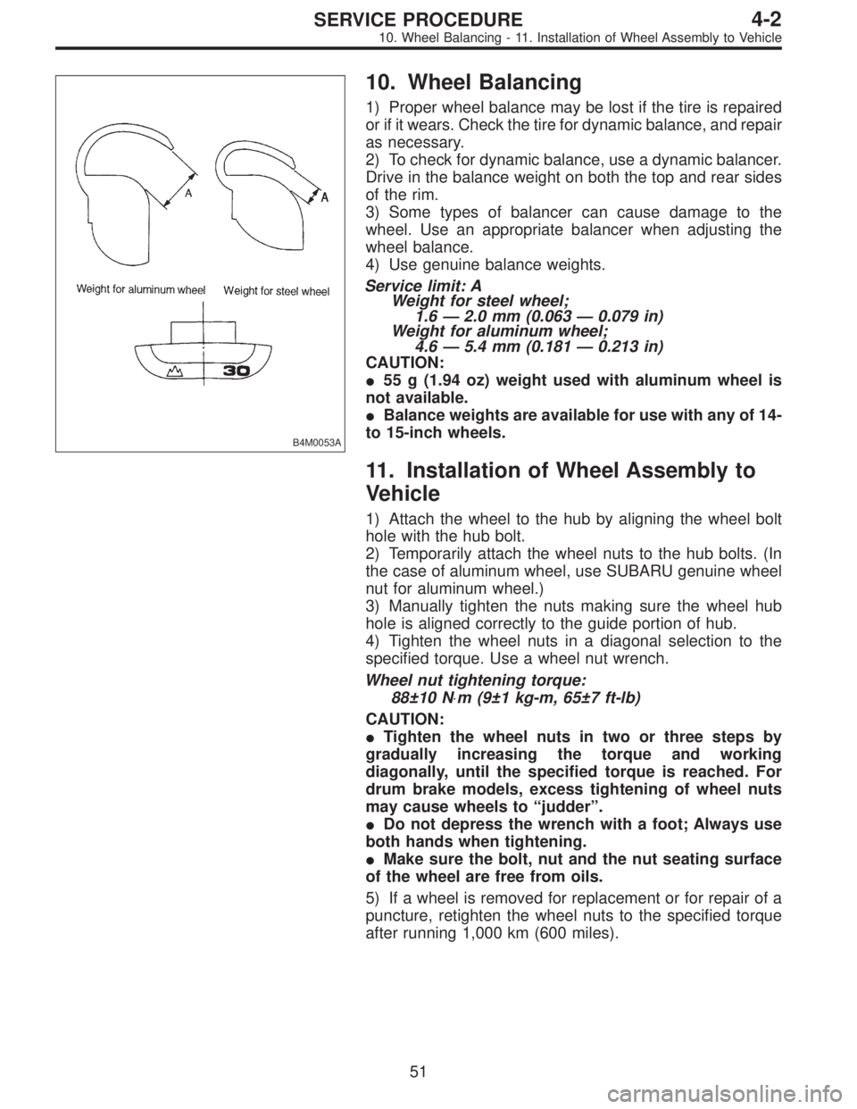
B4M0053A
10. Wheel Balancing
1) Proper wheel balance may be lost if the tire is repaired
or if it wears. Check the tire for dynamic balance, and repair
as necessary.
2) To check for dynamic balance, use a dynamic balancer.
Drive in the balance weight on both the top and rear sides
of the rim.
3) Some types of balancer can cause damage to the
wheel. Use an appropriate balancer when adjusting the
wheel balance.
4) Use genuine balance weights.
Service limit: A
Weight for steel wheel;
1.6—2.0 mm (0.063—0.079 in)
Weight for aluminum wheel;
4.6—5.4 mm (0.181—0.213 in)
CAUTION:
�55 g (1.94 oz) weight used with aluminum wheel is
not available.
�Balance weights are available for use with any of 14-
to 15-inch wheels.
11. Installation of Wheel Assembly to
Vehicle
1) Attach the wheel to the hub by aligning the wheel bolt
hole with the hub bolt.
2) Temporarily attach the wheel nuts to the hub bolts. (In
the case of aluminum wheel, use SUBARU genuine wheel
nut for aluminum wheel.)
3) Manually tighten the nuts making sure the wheel hub
hole is aligned correctly to the guide portion of hub.
4) Tighten the wheel nuts in a diagonal selection to the
specified torque. Use a wheel nut wrench.
Wheel nut tightening torque:
88±10 N⋅m (9±1 kg-m, 65±7 ft-lb)
CAUTION:
�Tighten the wheel nuts in two or three steps by
gradually increasing the torque and working
diagonally, until the specified torque is reached. For
drum brake models, excess tightening of wheel nuts
may cause wheels to “judder”.
�Do not depress the wrench with a foot; Always use
both hands when tightening.
�Make sure the bolt, nut and the nut seating surface
of the wheel are free from oils.
5) If a wheel is removed for replacement or for repair of a
puncture, retighten the wheel nuts to the specified torque
after running 1,000 km (600 miles).
51
4-2SERVICE PROCEDURE
10. Wheel Balancing - 11. Installation of Wheel Assembly to Vehicle
Page 1197 of 3342
B4M0555
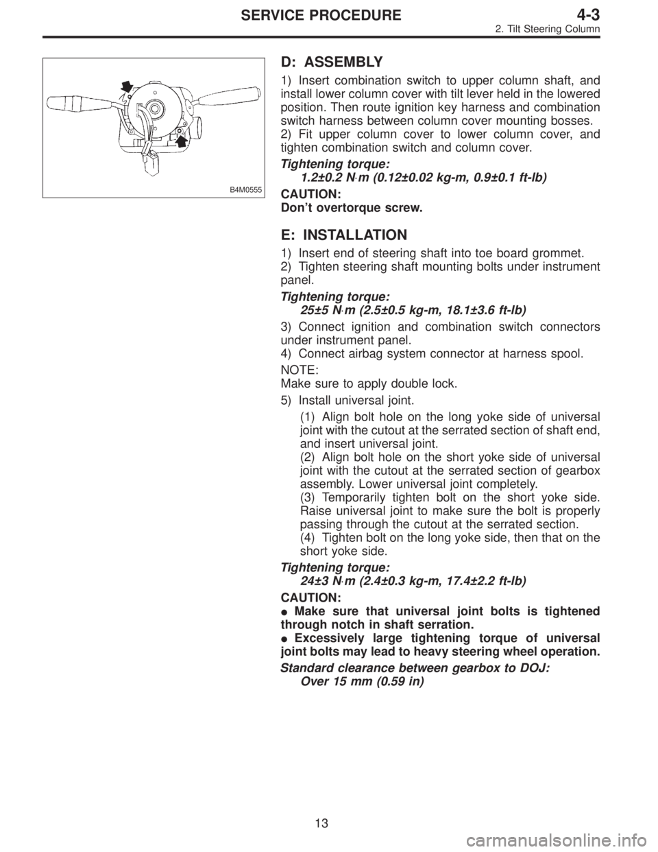
D: ASSEMBLY
1) Insert combination switch to upper column shaft, and
install lower column cover with tilt lever held in the lowered
position. Then route ignition key harness and combination
switch harness between column cover mounting bosses.
2) Fit upper column cover to lower column cover, and
tighten combination switch and column cover.
Tightening torque:
1.2±0.2 N⋅m (0.12±0.02 kg-m, 0.9±0.1 ft-lb)
CAUTION:
Don’t overtorque screw.
E: INSTALLATION
1) Insert end of steering shaft into toe board grommet.
2) Tighten steering shaft mounting bolts under instrument
panel.
Tightening torque:
25±5 N⋅m (2.5±0.5 kg-m, 18.1±3.6 ft-lb)
3) Connect ignition and combination switch connectors
under instrument panel.
4) Connect airbag system connector at harness spool.
NOTE:
Make sure to apply double lock.
5) Install universal joint.
(1) Align bolt hole on the long yoke side of universal
joint with the cutout at the serrated section of shaft end,
and insert universal joint.
(2) Align bolt hole on the short yoke side of universal
joint with the cutout at the serrated section of gearbox
assembly. Lower universal joint completely.
(3) Temporarily tighten bolt on the short yoke side.
Raise universal joint to make sure the bolt is properly
passing through the cutout at the serrated section.
(4) Tighten bolt on the long yoke side, then that on the
short yoke side.
Tightening torque:
24±3 N⋅m (2.4±0.3 kg-m, 17.4±2.2 ft-lb)
CAUTION:
�Make sure that universal joint bolts is tightened
through notch in shaft serration.
�Excessively large tightening torque of universal
joint bolts may lead to heavy steering wheel operation.
Standard clearance between gearbox to DOJ:
Over 15 mm (0.59 in)
13
4-3SERVICE PROCEDURE
2. Tilt Steering Column
Page 1210 of 3342
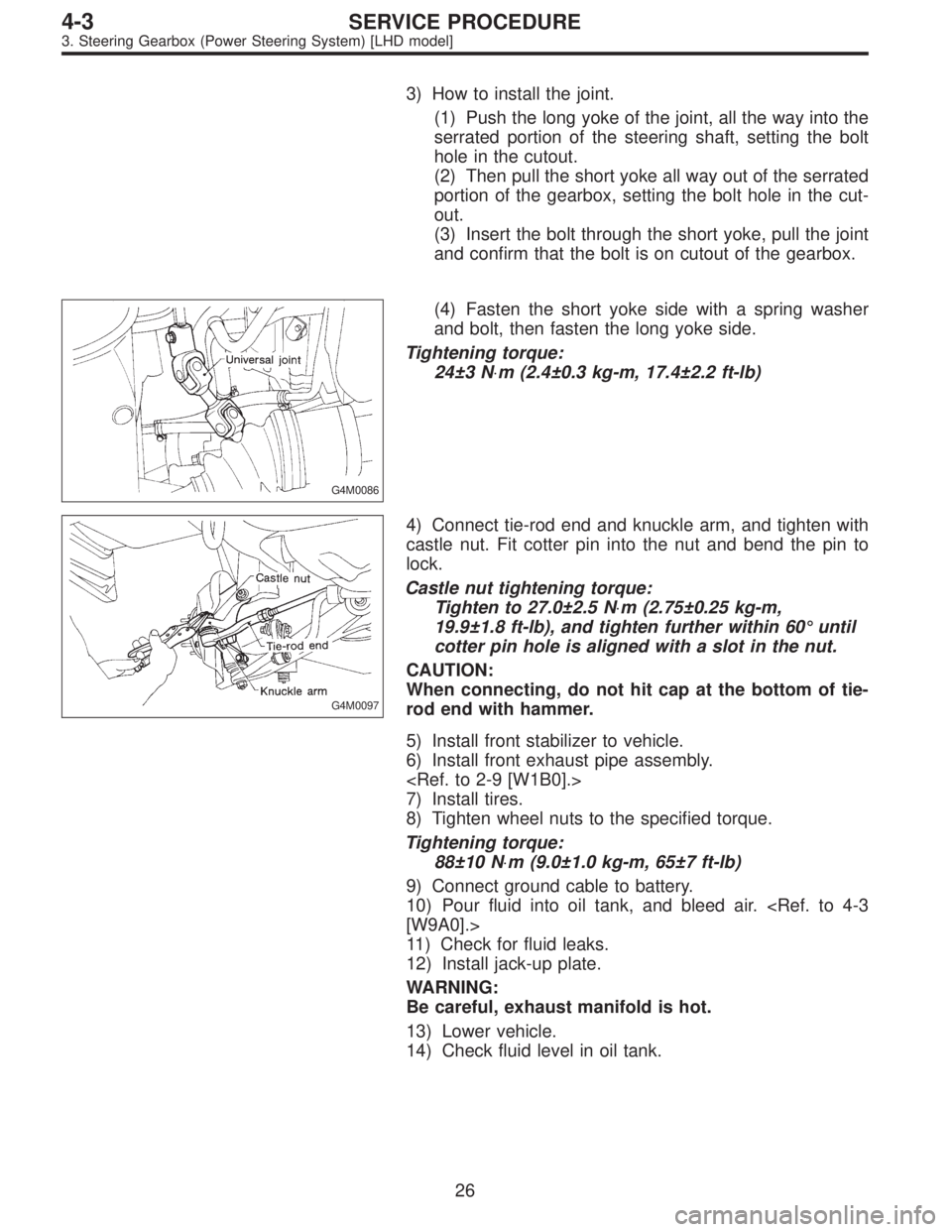
3) How to install the joint.
(1) Push the long yoke of the joint, all the way into the
serrated portion of the steering shaft, setting the bolt
hole in the cutout.
(2) Then pull the short yoke all way out of the serrated
portion of the gearbox, setting the bolt hole in the cut-
out.
(3) Insert the bolt through the short yoke, pull the joint
and confirm that the bolt is on cutout of the gearbox.
G4M0086
(4) Fasten the short yoke side with a spring washer
and bolt, then fasten the long yoke side.
Tightening torque:
24±3 N⋅m (2.4±0.3 kg-m, 17.4±2.2 ft-lb)
G4M0097
4) Connect tie-rod end and knuckle arm, and tighten with
castle nut. Fit cotter pin into the nut and bend the pin to
lock.
Castle nut tightening torque:
Tighten to 27.0±2.5 N⋅m (2.75±0.25 kg-m,
19.9±1.8 ft-lb), and tighten further within 60°until
cotter pin hole is aligned with a slot in the nut.
CAUTION:
When connecting, do not hit cap at the bottom of tie-
rod end with hammer.
5) Install front stabilizer to vehicle.
6) Install front exhaust pipe assembly.
7) Install tires.
8) Tighten wheel nuts to the specified torque.
Tightening torque:
88±10 N⋅m (9.0±1.0 kg-m, 65±7 ft-lb)
9) Connect ground cable to battery.
10) Pour fluid into oil tank, and bleed air.
[W9A0].>
11) Check for fluid leaks.
12) Install jack-up plate.
WARNING:
Be careful, exhaust manifold is hot.
13) Lower vehicle.
14) Check fluid level in oil tank.
26
4-3SERVICE PROCEDURE
3. Steering Gearbox (Power Steering System) [LHD model]
Page 1327 of 3342
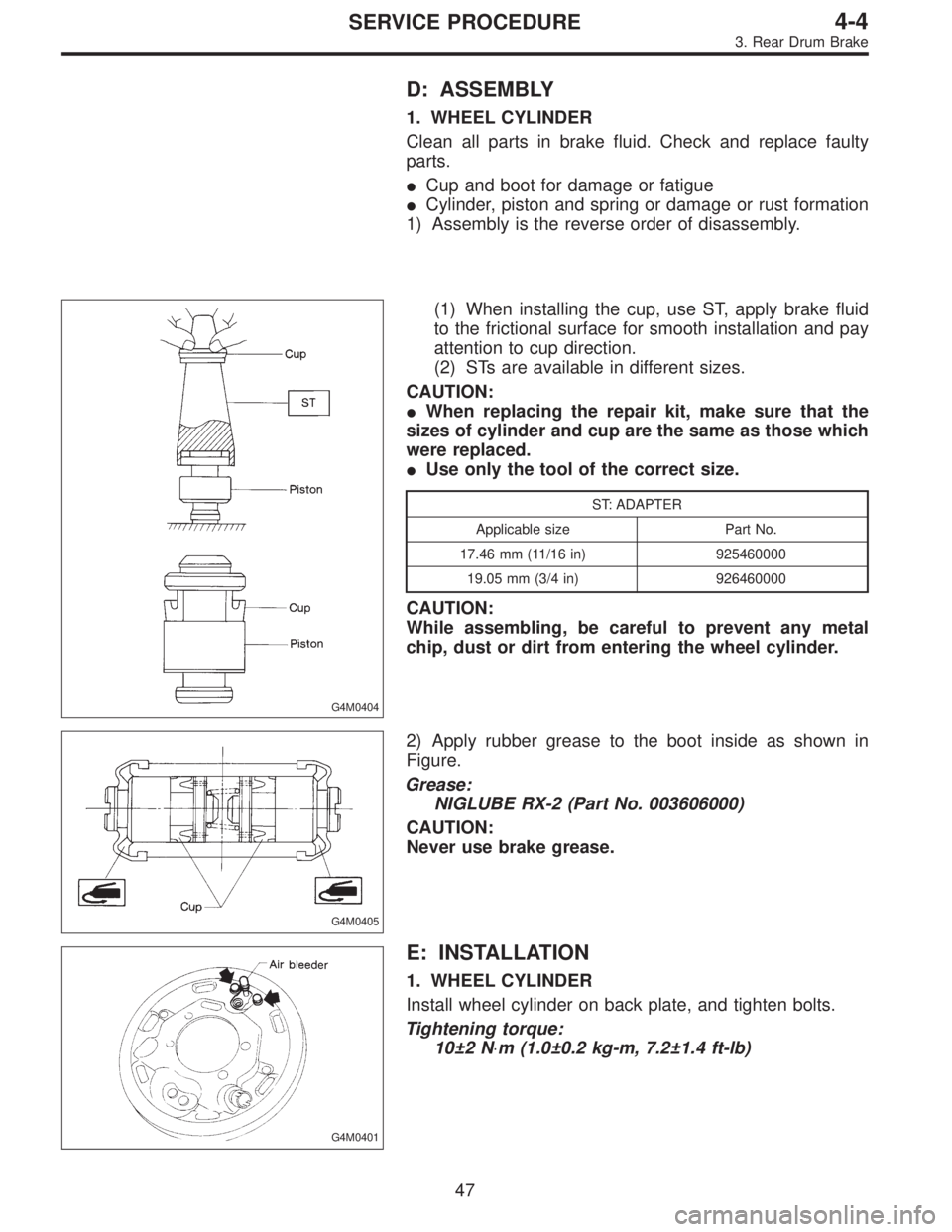
D: ASSEMBLY
1. WHEEL CYLINDER
Clean all parts in brake fluid. Check and replace faulty
parts.
�Cup and boot for damage or fatigue
�Cylinder, piston and spring or damage or rust formation
1) Assembly is the reverse order of disassembly.
G4M0404
(1) When installing the cup, use ST, apply brake fluid
to the frictional surface for smooth installation and pay
attention to cup direction.
(2) STs are available in different sizes.
CAUTION:
�When replacing the repair kit, make sure that the
sizes of cylinder and cup are the same as those which
were replaced.
�Use only the tool of the correct size.
ST: ADAPTER
Applicable size Part No.
17.46 mm (11/16 in) 925460000
19.05 mm (3/4 in) 926460000
CAUTION:
While assembling, be careful to prevent any metal
chip, dust or dirt from entering the wheel cylinder.
G4M0405
2) Apply rubber grease to the boot inside as shown in
Figure.
Grease:
NIGLUBE RX-2 (Part No. 003606000)
CAUTION:
Never use brake grease.
G4M0401
E: INSTALLATION
1. WHEEL CYLINDER
Install wheel cylinder on back plate, and tighten bolts.
Tightening torque:
10±2 N⋅m (1.0±0.2 kg-m, 7.2±1.4 ft-lb)
47
4-4SERVICE PROCEDURE
3. Rear Drum Brake
Page 1328 of 3342
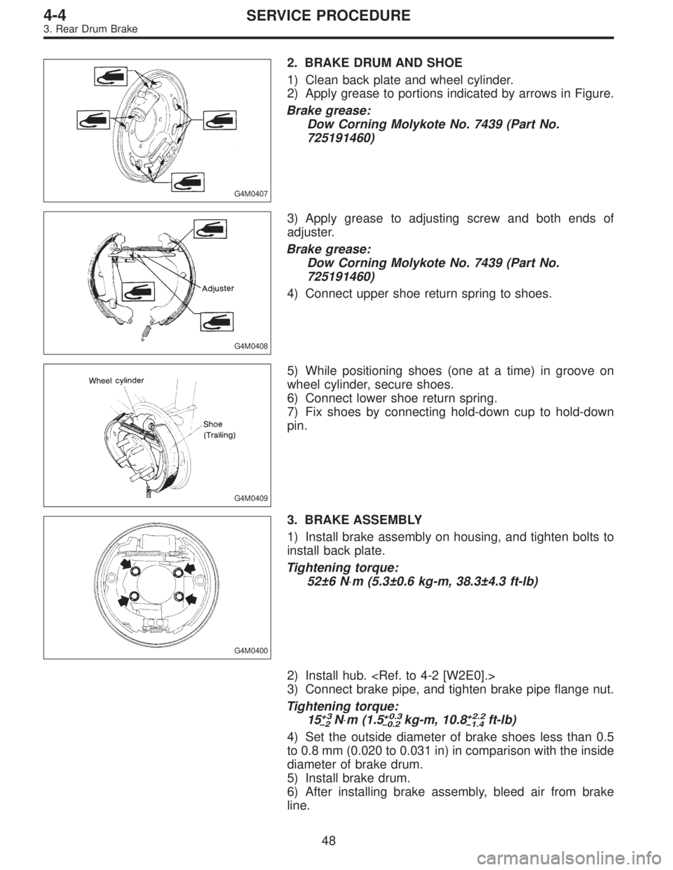
G4M0407
2. BRAKE DRUM AND SHOE
1) Clean back plate and wheel cylinder.
2) Apply grease to portions indicated by arrows in Figure.
Brake grease:
Dow Corning Molykote No. 7439 (Part No.
725191460)
G4M0408
3) Apply grease to adjusting screw and both ends of
adjuster.
Brake grease:
Dow Corning Molykote No. 7439 (Part No.
725191460)
4) Connect upper shoe return spring to shoes.
G4M0409
5) While positioning shoes (one at a time) in groove on
wheel cylinder, secure shoes.
6) Connect lower shoe return spring.
7) Fix shoes by connecting hold-down cup to hold-down
pin.
G4M0400
3. BRAKE ASSEMBLY
1) Install brake assembly on housing, and tighten bolts to
install back plate.
Tightening torque:
52±6 N⋅m (5.3±0.6 kg-m, 38.3±4.3 ft-lb)
2) Install hub.
3) Connect brake pipe, and tighten brake pipe flange nut.
Tightening torque:
15
+3
�2N⋅m (1.5+0.3
�0.2kg-m, 10.8+2.2
�1.4ft-lb)
4) Set the outside diameter of brake shoes less than 0.5
to 0.8 mm (0.020 to 0.031 in) in comparison with the inside
diameter of brake drum.
5) Install brake drum.
6) After installing brake assembly, bleed air from brake
line.
48
4-4SERVICE PROCEDURE
3. Rear Drum Brake