Page 382 of 3342
 Inspect the flange and stem of valve, and replace if
damaged, worn, or deformed, or if“H”is less than the
specified limit.
H:
Intake
Standard
1.2 mm (0.047 i")
G2M0153
4. INTAKE AND EXHAUST VALVE
1) Inspect the flange and stem of valve, and replace if
damaged, worn, or deformed, or if“H”is less than the
specified limit.
H:
Intake
Standard
1.2 mm (0.047 in)
Limit
0.8 mm (0.031 in)
Exhaust
Standard
1.5 mm (0.059 in)
Limit
0.8 mm (0.031 in)
Valve overall length:
Intake 105.9 mm (4.169 in)
Exhaust 106.2 mm (4.181 in)
2) Put a small amount of grinding compound on the seat
surface and lap the valve and seat surface. Install a new
intake valve oil seal after lapping.
G2M0154
5. VALVE SPRINGS
1) Check valve springs for damage, free length, and ten-
sion. Replace valve spring if it is not to the specifications
presented below.
2) To measure the squareness of the valve spring, stand
the spring on a surface plate and measure its deflection at
the top using a try square.
Valve spring
Free length 48.04 mm (1.8913 in)
Tension/spring height146.1—167.7 N
(14.9—17.1 kg, 32.9—37.7 lb)/42.0 mm
(1.654 in)
455.0—523.7 N
(46.4—53.4 kg, 102.3—117.7 lb)/33.4 mm
(1.315 in)
Squareness 2.5°, 2.1 mm (0.083 in)
G2M0765
6. INTAKE AND EXHAUST VALVE OIL SEAL
Replace oil seal with new one, if lip is damaged or spring
out of place, or when the surfaces of intake valve and valve
seat are reconditioned or intake valve guide is replaced.
1) Place cylinder head on ST1.
2) Press in oil seal to the specified dimension indicated in
the figure by using ST2.
ST1 498267600 CYLINDER HEAD TABLE
ST2 498857100 VALVE OIL SEAL GUIDE
41
2-3bSERVICE PROCEDURE
4. Cylinder Head
Page 383 of 3342
CAUTION:
�Apply engine oil to oil seal before force-fitting.
�Differentiate between intake valve oil seal and
exhaust valve oil seal by noting their difference in
color.
Color of rubber part:
Intake [Black]
Exhaust [Brown]
Color of spring part:
Intake [Black]
Exhaust [Black]
G2M0766
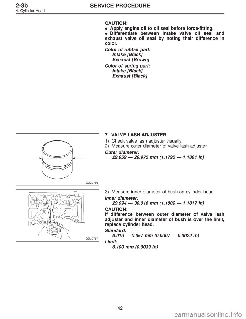
7. VALVE LASH ADJUSTER
1) Check valve lash adjuster visually.
2) Measure outer diameter of valve lash adjuster.
Outer diameter:
29.959—29.975 mm (1.1795—1.1801 in)
G2M0767
3) Measure inner diameter of bush on cylinder head.
Inner diameter:
29.994—30.016 mm (1.1809—1.1817 in)
CAUTION:
If difference between outer diameter of valve lash
adjuster and inner diameter of bush is over the limit,
replace cylinder head.
Standard:
0.019—0.057 mm (0.0007—0.0022 in)
Limit:
0.100 mm (0.0039 in)
42
2-3bSERVICE PROCEDURE
4. Cylinder Head
Page 384 of 3342
B2M1222
8. VALVE LIFTER
1) Check valve lifter for scratch or uneven wear.
2) Measure outer diameter of valve lifter.
Outer diameter:
32.959—32.975 mm (1.2976—1.2982 in)
G2M0767
3) Measure inner diameter of valve lifter mating part on
cylinder head.
Inner diameter:
32.994—33.016 mm (1.2990—1.2998 in)
CAUTION:
If difference between outer diameter of valve lifter and
inner diameter of valve lifter mating part is over the
limit, replace cylinder head.
Standard:
0.019—0.057 mm (0.0007—0.0022 in)
Limit:
0.100 mm (0.0039 in)
43
2-3bSERVICE PROCEDURE
4. Cylinder Head
Page 385 of 3342
D: ASSEMBLY
B2M1220B
B2M1221A
1) Installation of valve spring and valve
(1) Coat stem of each valve with engine oil and insert
valve into valve guide.
CAUTION:
When inserting valve into valve guide, use special care
not to damage the oil seal lip.
(2) Set cylinder head on ST1.
(3) Install valve spring and retainer using ST2.
ST1 498267600 CYLINDER HEAD TABLE
ST2 499718000 VALVE SPRING REMOVER
CAUTION:
Be sure to install the valve springs with their painted
facing towards the valve spring retainer.
(4) Compress valve spring and fit valve spring retainer
key.
(5) After installing, tap valve spring retainers lightly
with wooden hammer for better seating.
2) Install valve lifter and shim.
44
2-3bSERVICE PROCEDURE
4. Cylinder Head
Page 386 of 3342
E: INSTALLATION
1. CYLINDER HEAD
B2M0771A
1) Install cylinder head and gaskets on cylinder block.
CAUTION:
Use new cylinder head gaskets.
G2M0771
2) Tighten cylinder head bolts.
(1) Apply a coat of engine oil to washers and bolt
threads.
(2) Tighten all bolts to 29 N⋅m (3.0 kg-m, 22 ft-lb) in
numerical sequence.
Then tighten all bolts to 69 N⋅m (7.0 kg-m, 51 ft-lb) in
numerical sequence.
(3) Back off all bolts by 180°first; back them off by 180°
again.
(4) Tighten bolts�
1and�2to 34 N⋅m (3.5 kg-m, 25 ft-
lb).
(5) Tighten bolts�
3,�4,�5and�6to 15 N⋅m (1.5 kg-m,
11 ft-lb).
(6) Tighten all bolts by 80 to 90°in numerical
sequence.
CAUTION:
Do not tighten bolts more than 90°.
45
2-3bSERVICE PROCEDURE
4. Cylinder Head
Page 387 of 3342
(7) Further tighten all bolts by 80 to 90°in numerical
sequence.
CAUTION:
Ensure that the total“re-tightening angle”[steps (6)
and (7) above] do not exceed 180°.
3) Install oil level gauge guide attaching bolt (left side
only).
2. INTAKE MANIFOLD
1) Install camshafts, rocker cover and related parts.
G2M0750
Tightening torque: N⋅m (kg-m, ft-lb)
T1: 10±0.7 (1.0±0.07, 7.2±0.5)
T2: 20±2 (2.0±0.2, 14.5±1.4)
46
2-3bSERVICE PROCEDURE
4. Cylinder Head
Page 388 of 3342
2) Install camshaft sprockets, timing belt and related parts.
B2M0702
B2M0703
3) Install engine coolant pipe.
CAUTION:
Use new gaskets.
47
2-3bSERVICE PROCEDURE
4. Cylinder Head
Page 389 of 3342
G2M0774
4) Install intake manifold.
CAUTION:
Use new gaskets.
5) Install coolant filler tank.
6) Install crankshaft position sensor, camshaft position
sensor and knock sensor. Use dry compressed air to
remove foreign particles before installing sensors.
7) Connect each connector and/or install connector
bracket.
8) Connect hoses and tubes to cylinder block.
9) Install brackets, generator and air conditioner compres-
sor.
10) Install V-belt.
48
2-3bSERVICE PROCEDURE
4. Cylinder Head
 Check valve lifter for scratch or uneven wear.
2) Measure outer diameter of valve lifter.
Outer diameter:
32.959—32.975 mm (1.2976—1.2982 in)
G2M0767
3) Measure inner di")
 Installation of valve spring and valve
(1) Coat stem of each valve with engine oil and insert
valve into valve guide.
CAUTION:
When inserting valve into valve guide, u")
 Install cylinder head and gaskets on cylinder block.
CAUTION:
Use new cylinder head gaskets.
G2M0771
2) Tighten cylinder head bolts.
(1) Apply a coat of en")
![SUBARU LEGACY 1997 Service Repair Manual (7) Further tighten all bolts by 80 to 90°in numerical
sequence.
CAUTION:
Ensure that the total“re-tightening angle”[steps (6)
and (7) above] do not exceed 180°.
3) Install oil level gauge guide](/manual-img/17/57434/w960_57434-386.png "SUBARU LEGACY 1997 Service Repair Manual (7) Further tighten all bolts by 80 to 90°in numerical
sequence.
CAUTION:
Ensure that the total“re-tightening angle”[steps (6)
and (7) above] do not exceed 180°.
3) Install oil level gauge guide")
![SUBARU LEGACY 1997 Service Repair Manual 2) Install camshaft sprockets, timing belt and related parts.
<Ref. to 2-3b [W2C0].>
B2M0702
B2M0703
3) Install engine coolant pipe.
CAUTION:
Use new gaskets.
47
2-3bSERVICE PROCEDURE
4. Cylinder Head](/manual-img/17/57434/w960_57434-387.png "SUBARU LEGACY 1997 Service Repair Manual 2) Install camshaft sprockets, timing belt and related parts.
<Ref. to 2-3b [W2C0].>
B2M0702
B2M0703
3) Install engine coolant pipe.
CAUTION:
Use new gaskets.
47
2-3bSERVICE PROCEDURE
4. Cylinder Head")
 Install intake manifold.
CAUTION:
Use new gaskets.
5) Install coolant filler tank.
6) Install crankshaft position sensor, camshaft position
sensor and knock sensor. Use dry compressed air t")