Page 374 of 3342
C: INSTALLATION
1. CAMSHAFT
B2M1304F
Tightening torque: N⋅m (kg-m, ft-lb)
T1: 5±0.5 (0.5±0.05, 3.6±0.4)
T2: 10±0.7 (1.0±0.07, 7.2±0.5)
T3: 20±2 (2.0±0.2, 14.5±1.4)
B2M1200A
1) Camshaft installation
Apply engine oil to cylinder head at camshaft bearing loca-
tion before installing camshaft. Install camshaft so that
rocker arm is close to or in contact with“base circle”of cam
lobe.
CAUTION:
�When camshafts are positioned as shown in figure,
camshafts need to be rotated at a minimum to align
with timing belt during installation.
�Right-hand camshaft need not be rotated when set
at position shown in figure.
Left-hand intake camshaft: Rotate 80°clockwise.
Left-hand exhaust camshaft: Rotate 45°counter-clock-
wise.
33
2-3bSERVICE PROCEDURE
3. Camshaft
Page 375 of 3342
 Camshaft cap installation
(1) Apply fluid packing sparingly to cap mating surface.
CAUTION:
Do not apply fluid packing excessively. Failure to do so
may cause excess packing to come out and")
G2M0752
2) Camshaft cap installation
(1) Apply fluid packing sparingly to cap mating surface.
CAUTION:
Do not apply fluid packing excessively. Failure to do so
may cause excess packing to come out and flow
toward oil seal, resulting in oil leaks.
Fluid packing:
THREE BOND 1215 or equivalent
G2M0753
(2) Apply engine oil to cap bearing surface and install
cap on camshaft as shown by identification mark.
(3) Gradually tighten cap in at least two stages in the
numerical order shown in figure, and then tighten to
specified torque.
(4) Similarly, tighten cap on exhaust side.
After tightening cap, ensure camshaft rotates only
slightly while holding it at“base”circle.
B2M1219A
3) Inspect for valve clearance.
Measure valve clearances using thickness gauge.
2-2 [07A2].>
If necessary, adjust valve clearances.
G2M0754
4) Camshaft oil seal installation
Apply grease to new oil seal lips and press onto front end
of camshaft by using ST1 and ST2.
CAUTION:
Use a new oil seal.
ST1 499587100 OIL SEAL INSTALLER
ST2 499597000 OIL SEAL GUIDE
G2M0755
5) Rocker cover installation
(1) Install gaskets on rocker cover.
Install peripheral rocker cover gaskets.
(2) Apply fluid packing to four front open edges of
peripheral gasket.
Fluid packing:
THREE BOND 1215 or equivalent
(3) Install rocker cover on cylinder head. Ensure gas-
ket is properly positioned during installation.
34
2-3bSERVICE PROCEDURE
3. Camshaft
Page 376 of 3342
6) Install spark plug cords.
7) Install camshaft position sensor.
8) Similarly, install parts on right-hand side.
2. RELATED PARTS
Install timing belt, camshaft sprockets and related parts.
35
2-3bSERVICE PROCEDURE
3. Camshaft
Page 377 of 3342
4. Cylinder Head
A: REMOVAL
1. INTAKE MANIFOLD
1) Remove V-belt.
2) Remove generator, air conditioner compressor and
brackets.
3) Remove hoses and tubes from cylinder block.
4) Disconnect each connector and/or remove connector
bracket.
5) Remove coolant filler tank.
6) Remove intake manifold assembly and gasket.
7) Remove water pipe.
8) Remove crank angle sensor, cam angle sensor and
knock sensor.
9) Remove timing belt, camshaft sprockets and related
parts.
10) Remove rocker cover, camshafts and related parts.
2. CYLINDER HEAD
B2M0770A
36
2-3bSERVICE PROCEDURE
4. Cylinder Head
Page 378 of 3342
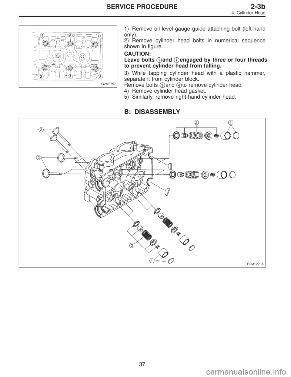
G2M0757
1) Remove oil level gauge guide attaching bolt (left-hand
only).
2) Remove cylinder head bolts in numerical sequence
shown in figure.
CAUTION:
Leave bolts�
1and�4engaged by three or four threads
to prevent cylinder head from falling.
3) While tapping cylinder head with a plastic hammer,
separate it from cylinder block.
Remove bolts�
1and�4to remove cylinder head.
4) Remove cylinder head gasket.
5) Similarly, remove right-hand cylinder head.
B: DISASSEMBLY
B2M1220A
37
2-3bSERVICE PROCEDURE
4. Cylinder Head
Page 379 of 3342
 Remove shims and valve lifters.
2) Compress the valve spring and remove the valve spring
retainer key. Remove each valve and valve spring.
ST1 498267600 CYLINDER HEAD TABLE
ST2 499718000 V")
B2M1221A
1) Remove shims and valve lifters.
2) Compress the valve spring and remove the valve spring
retainer key. Remove each valve and valve spring.
ST1 498267600 CYLINDER HEAD TABLE
ST2 499718000 VALVE SPRING REMOVER
CAUTION:
�Keep removed parts in order for re-installing in their
original positions.
�Mark each valve to prevent confusion.
�Use extreme care not to damage the lips of the
intake valve oil seals and exhaust valve oil seals.
G2M0760
C: INSPECTION
1. CYLINDER HEAD
1) Make sure that no crack or other damage exists. In
addition to visual inspection, inspect important areas by
means of red check.
2) Measure the warping of the cylinder head surface that
mates with crankcase by using a straight edge and thick-
ness gauge.
If the warping exceeds 0.05 mm (0.0020 in), regrind the
surface with a surface grinder.
Warping limit:
0.05 mm (0.0020 in)
Grinding limit:
0.3 mm (0.012 in)
Standard height of cylinder head:
127.5 mm (5.02 in)
CAUTION:
Uneven torque for the cylinder head nuts can cause
warping. When reassembling, pay special attention to
the torque so as to tighten evenly.
38
2-3bSERVICE PROCEDURE
4. Cylinder Head
Page 380 of 3342
G2M0761
2. VALVE SEAT
Inspect intake and exhaust valve seats, and correct the
contact surfaces with valve seat cutter if they are defective
or when valve guides are replaced.
Valve seat width: W
Intake
Standard
1.0 mm (0.039 in)
Limit
1.7 mm (0.067 in)
Exhaust
Standard
1.5 mm (0.059 in)
Limit
2.2 mm (0.087 in)
3. VALVE GUIDE
1) Check the clearance between valve guide and stem.
The clearance can be checked by measuring the outside
diameter of valve stem and the inside diameter of valve
guide with outside and inside micrometers respectively.
Clearance between the valve guide and valve stem:
Standard
Intake
0.035—0.062 mm (0.0014—0.0024 in)
Exhaust
0.040—0.067 mm (0.0016—0.0026 in)
Limit
0.15 mm (0.0059 in)
Valve guide inner diameter:
6.000—6.015 mm (0.2362—0.2368 in)
Valve stem outer diameter:
Intake
5.950—5.965 mm (0.2343—0.2348 in)
Exhaust
5.950—5.965 mm (0.2343—0.2348 in)
39
2-3bSERVICE PROCEDURE
4. Cylinder Head
Page 381 of 3342
 If the clearance between valve guide and stem exceeds
the specification, replace guide as follows:
(1) Place cylinder head on ST1 with the combustion
chamber upward so that valve guides ent")
G2M0762
2) If the clearance between valve guide and stem exceeds
the specification, replace guide as follows:
(1) Place cylinder head on ST1 with the combustion
chamber upward so that valve guides enter the holes
in ST1.
(2) Insert ST2 into valve guide and press it down to
remove valve guide.
ST1 498267600 CYLINDER HEAD TABLE
ST2 499767200 VALVE GUIDE REMOVER
G2M0763
(3) Turn cylinder head upside down and place ST as
shown in the figure.
ST 498267700 VALVE GUIDE ADJUSTER
G2M0764
(4) Before installing new valve guide, make sure that
neither scratches nor damages exist on the inside sur-
face of the valve guide holes in cylinder head.
(5) Put new valve guide, coated with sufficient oil, in
cylinder, and insert ST1 into valve guide. Press in until
the valve guide upper end is flush with the upper sur-
face of ST2.
ST1 499767200 VALVE GUIDE REMOVER
ST2 498267700 VALVE GUIDE ADJUSTER
(6) Check the valve guide protrusion.
Valve guide protrusion: L
12.0—12.4 mm (0.472—0.488 in)
(7) Ream the inside of valve guide with ST. Gently
rotate the reamer clockwise while pressing it lightly into
valve guide, and return it also rotating clockwise. After
reaming, clean valve guide to remove chips.
ST 499767400 VALVE GUIDE REAMER
CAUTION:
�Apply engine oil to the reamer when reaming.
�If the inner surface of the valve guide is torn, the
edge of the reamer should be slightly ground with an
oil stone.
�If the inner surface of the valve guide becomes lus-
trous and the reamer does not chips, use a new reamer
or remedy the reamer.
(8) Recheck the contact condition between valve and
valve seat after replacing valve guide.
40
2-3bSERVICE PROCEDURE
4. Cylinder Head

T1: 5±0.5 (0.5±0.05, 3.6±0.4)
T2: 10±0.7 (1.0±0.07, 7.2±0.5)
T3: 20±2 (2.0±0.2, 14.5±1.4)
B2M1200A
1) Camshaft inst")
 Install spark plug cords.
7) Install camshaft position sensor.
8) Similarly, install parts on right-hand side.
2. RELATED PARTS
Install timing belt, camshaft sprockets and related parts.
<Ref. to 2")
 Remove V-belt.
2) Remove generator, air conditioner compressor and
brackets.
3) Remove hoses and tubes from cylinder block.
4) Disconnect each connect")