Page 366 of 3342
(6) Ensure camshaft and crankshaft sprockets are
positioned as shown.
G2M0734
G2M0735
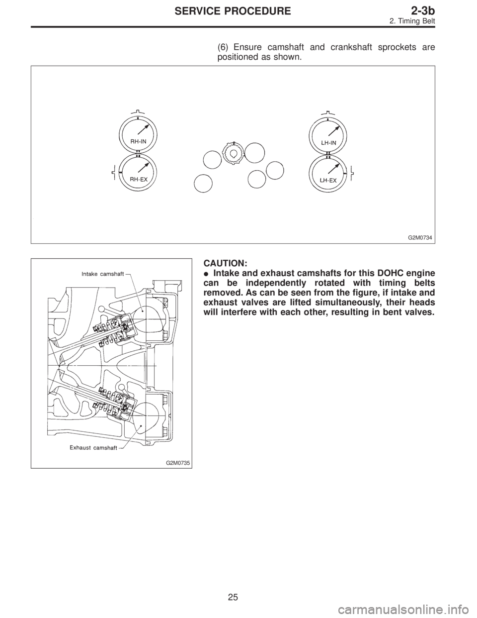
CAUTION:
�Intake and exhaust camshafts for this DOHC engine
can be independently rotated with timing belts
removed. As can be seen from the figure, if intake and
exhaust valves are lifted simultaneously, their heads
will interfere with each other, resulting in bent valves.
25
2-3bSERVICE PROCEDURE
2. Timing Belt
Page 367 of 3342

B2M0698A
�When timing belts are not installed, four camshafts
are held at the“zero-lift”position, where all cams on
camshafts do not push intake and exhaust valves
down. (Under this condition, all valves remain
unlifted.)
�When camshafts are rotated to install timing belts,
#2 intake and #4 exhaust cam of left-hand camshafts
are held to push their corresponding valves down.
(Under this condition, these valves are held lifted.)
Right-side camshafts are held so that their cams do
not push valves down.
�Left-hand camshafts must be rotated from the“zero-
lift”position to the position where timing belt is to be
installed at as small an angle as possible, in order to
prevent mutual interference of intake and exhaust
valve heads.
�Do not allow camshafts to rotate in the direction
shown in the upper of figure as this causes both intake
and exhaust valves to lift simultaneously, resulting in
interference with their heads.
B2M0699
2) Installation of timing belt
Align alignment mark on timing belt with marks on sprock-
ets in the numerical order shown in figure. While aligning
marks, position timing belt properly.
CAUTION:
Ensure belt’s rotating direction is correct.
G2M0738
26
2-3bSERVICE PROCEDURE
2. Timing Belt
Page 368 of 3342
G2M0739
3) Install belt idler.
CAUTION:
Make sure that the marks on timing belt and sprockets
are aligned.
B2M0700
4) Loosen tension adjuster attaching bolts and move
adjuster all the way to the left. Tighten the bolts.
G2M0741
5) After ensuring that the marks on timing belt and sprock-
ets are aligned, remove stopper pin from tension adjuster.
27
2-3bSERVICE PROCEDURE
2. Timing Belt
Page 369 of 3342
4. CRANKSHAFT PULLEY AND BELT COVER
B2M1215B
Tightening torque: N⋅m (kg-m, ft-lb)
T1: 5±0.5 (0.5±0.05, 3.6±0.4)
T2: 177±10 (18.0±1.0, 130±7)
B2M0731
1) Install front belt cover.
B2M0730
2) Install right-hand belt cover.
B2M0729
3) Install left-hand belt cover.
4) Install crankshaft pulley.
28
2-3bSERVICE PROCEDURE
2. Timing Belt
Page 370 of 3342
G2M0711
5) Install pulley bolt by using ST.
ST 499977100 CRANKSHAFT PULLEY WRENCH
6) Install V-belt.
CAUTION:
After installing V-belt, check and adjust V-belt tension.
29
2-3bSERVICE PROCEDURE
2. Timing Belt
Page 371 of 3342
3. Camshaft
A: REMOVAL
1. RELATED PARTS
Remove timing belt, camshaft sprockets and related parts.
2. CAMSHAFT LH
G2M0743
1) Remove camshaft position sensor.
2) Remove ignition coils.
3) Remove rocker cover and gasket.
G2M0744
4) Loosen intake camshaft cap bolts equally, a little at a
time in the numerical sequence shown in figure.
5) Remove camshaft caps and intake camshaft.
30
2-3bSERVICE PROCEDURE
3. Camshaft
Page 372 of 3342
 Loosen exhaust camshaft cap bolts equally, a little at a
time in the numerical sequence shown in figure.
7) Remove camshaft caps and exhaust camshaft.
CAUTION:
Arrange camshaft caps in orde")
G2M0745
6) Loosen exhaust camshaft cap bolts equally, a little at a
time in the numerical sequence shown in figure.
7) Remove camshaft caps and exhaust camshaft.
CAUTION:
Arrange camshaft caps in order so that they can be
installed in their original positions.
8) Similarly, remove right-hand camshafts and related
parts.
G2M0746
B: INSPECTION
1. CAMSHAFT
1) Measure the bend, and repair or replace if necessary.
Limit:
0.020 mm (0.0008 in)
2) Check journal for damage and wear. Replace if faulty.
3) Measure outside diameter of camshaft journal. If the
journal diameter is not as specified, check the oil clear-
ance.
Camshaft journal
Front Center, rear
Standard31.946—31.963 mm
(1.2577—1.2584 in)27.946—27.963 mm
(1.1002—1.1009 in)
B2M1216
4) Measurement of the camshaft journal oil clearance
(1) Clean the bearing caps and camshaft journals.
(2) Place the camshafts on the cylinder head. (Without
installing valve rocker.)
(3) Place plastigauge across each of the camshaft
journals.
(4) Install the bearing caps.
CAUTION:
Do not turn the camshaft.
(5) Remove the bearing caps.
(6) Measure the widest point of the plastigauge on
each journal.
If the oil clearance exceeds the limit, replace the cam-
shaft. If necessary, replace the camshaft caps and cyl-
inder head as a set.
Standard oil clearance:
0.037—0.072 mm (0.0015—0.0028 in)
Limit:
0.10 mm (0.0039 in)
(7) Completely remove the plastigauge.
31
2-3bSERVICE PROCEDURE
3. Camshaft
Page 373 of 3342
B2M1209A
5) Check cam face condition; remove minor faults by
grinding with oil stone. Measure the cam height H; replace
if the limit has been exceeded.
Cam height: H
Standard:
Intake:
42.20—42.30 mm (1.6614—1.6654 in)
Exhaust:
Front: 42.50—42.60 mm (1.6732—1.6772 in)
Rear: 41.40—41.50 mm (1.6299—1.6339 in)
Limit:
Intake:
42.04 mm (1.6551 in)
Exhaust:
Front: 42.34 mm (1.6669 in)
Rear: 41.24 mm (1.6236 in)
Cam base circle diameter A:
28.0 mm (1.102 in)
B2M1217
6) Measure the thrust clearance of camshaft with dial
gauge. If the clearance exceeds the limit, replace caps and
cylinder head as a set. If necessary replace camshaft.
Standard:
0.040—0.080 mm (0.0016—0.0031 in)
Limit:
0.1 mm (0.004 in)
32
2-3bSERVICE PROCEDURE
3. Camshaft
 Install belt idler.
CAUTION:
Make sure that the marks on timing belt and sprockets
are aligned.
B2M0700
4) Loosen tension adjuster attaching bolts and move
adjuster all the way to the left.")

T1: 5±0.5 (0.5±0.05, 3.6±0.4)
T2: 177±10 (18.0±1.0, 130±7)
B2M0731
1) Install front belt cover.
B2M0730
2) Ins")
 Install pulley bolt by using ST.
ST 499977100 CRANKSHAFT PULLEY WRENCH
6) Install V-belt.
CAUTION:
After installing V-belt, check and adjust V-belt tension.
29
2-3bSERVICE PROCEDURE
2. Timi")
![SUBARU LEGACY 1997 Service Repair Manual 3. Camshaft
A: REMOVAL
1. RELATED PARTS
Remove timing belt, camshaft sprockets and related parts.
<Ref. to 2-3b [W2A0].>
2. CAMSHAFT LH
G2M0743
1) Remove camshaft position sensor.
2) Remove ignition c](/manual-img/17/57434/w960_57434-370.png "SUBARU LEGACY 1997 Service Repair Manual 3. Camshaft
A: REMOVAL
1. RELATED PARTS
Remove timing belt, camshaft sprockets and related parts.
<Ref. to 2-3b [W2A0].>
2. CAMSHAFT LH
G2M0743
1) Remove camshaft position sensor.
2) Remove ignition c")
 Check cam face condition; remove minor faults by
grinding with oil stone. Measure the cam height H; replace
if the limit has been exceeded.
Cam height: H
Standard:
Intake:
42.20—42.30 mm")